


®


 SD-13-4830
Bendix® M-30™ AntiLock Modulator Assembly
Supply Port |
M-30™ Modulator |
(cast in 1, SUP) |
|
|
Delivery Port |
|
(cast in 2, DEL) |
Electrical Connector
|
|
|
|
|
|
Mounting Holes |
|
|
|
|
|
|
|
(.33" diameter thru body) |
|
|
|
|
|
|
|
|
|
|
|
|
|
|
Exhaust Port |
||
|
|
|
|
|
(cast in 3, EXH) |
||
|
|
|
|
|
|
|
|
|
FIGURE 1: M-30™ MODULATOR |
|
|
|
|
||
|
|
|
|
|
|
|
|
Solenoid |
|
Supply Port |
|||||
Connector |
|
(cast in 1) |
|||||
|
|
|
Supply Port |
|
|
|
Delivery Port |
|
|
|
|
|
|
(cast in 2) |
|
|
|
|
(cast in 1) |
|
|
|
|
|
|
|
|
|
|
|
|
Delivery Port |
|
Solenoid |
|||||
(cast in 2) |
|
Connector |
|||||
|
|
|
Mounting |
|
|
|
|
|
|
|
Holes |
|
|
Mounting |
|
|
|
|
|
|
|
||
|
|
|
|
|
|
Holes |
|
|
|
|
Exhaust |
|
|
|
Exhaust |
|
|
|
|
|
|
(cast in 3) |
|
|
|
|
(cast in 3) |
|
|
|
|
|
|
|
|
|
|
||
|
|
|
|
|
|
|
|
FIGURE 2: M-21™ MODULATOR |
|
FIGURE 3: M-22™ MODULATOR |
|||||
DESCRIPTION
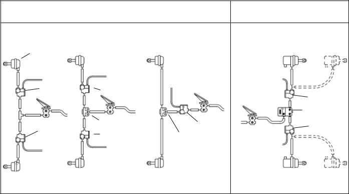
The Bendix® M-30™ modulator replaced both the M-21™ (Figure 2) and M-22™ (Figure 3) modulators in all applications.
The M-30™ antilock system modulator (Figure 1) is a high capacity, on/off air valve that incorporates a pair of electrical solenoids for control. The solenoids provide the electropneumatic interface between the antilock controller electronics and the air brake system. The modulator is used to control the braking function on individual or dual service actuators during antilock activity. When used to control both service chambers on an axle or two chambers on the same side of a tandem axle, the modulator is sometimes mounted ahead of a quick release valve, which provides quick exhaust of service applications during normal
braking (Figure 4). In the case of individual wheel control applications, the modulator is always the last control valve through which air passes on its way to the service brake actuator.
The modulator consists of a die cast aluminum body and a solenoid assembly which contains one normally open solenoid, one normally closed solenoid, and an inlet and exhaust diaphragm valve. A three pin, weather resistant electrical connector is an integral part of the modulator solenoid assembly and serves to carry control commands from the antilock controller to the modulator. Two mounting holes are provided for frame or cross member mounting of the valve.
1
FRONT AXLE SYSTEMS
WHEEL CONTROL |
WHEEL CONTROL |
AXLE |
|
|
CONTROL |
SERVICE |
|
|
BRAKE |
|
|
CHAMBER |
|
TO |
TO ANTILOCK |
|
|
|
ANTILOCK |
|
CONTROLLER |
TO ANTILOCK |
CONTROLLER |
|
CONTROLLER |
|
M-30™ |
M-30™ MODULATOR |
|
MODULATOR |
|
|
|
OR |
OR |
|
|
|
QUICK RELEASE VALVE |
M-30™ MODULATOR |
||
M-30™ |
M-30™ |
MODULATOR |
QUICK RELEASE VALVE |
|
MODULATOR |
|
|
|
|
|
|
TO ANTILOCK |
|
|
|
|
CONTROLLER |
|
|
TO |
|
|
|
|
ANTILOCK |
|
|
|
|
CONTROLLER |
SERVICE |
SERVICE |
||
SERVICE |
||||
BRAKE |
|
BRAKE |
||
BRAKE |
|
|||
CHAMBER |
CHAMBER |
|||
CHAMBER |
||||
|
|
|
||
FIGURE 4: TYPICAL WHEEL AND AXLE CONTROL SYSTEMS
REAR AXLE SYSTEM
WHEEL CONTROL
TO ANTILOCK
CONTROLLER
M-30™
MODULATOR
CONTROLLER/
RELAY
ASSEMBLY
M-30™
MODULATOR
TO
ANTILOCK 
CONTROLLER
SERVICE &
SPRING
BRAKE
CHAMBER
NOTE: USE OF A QUICK RELEASE VALVE IS NOT TYPICALLY REQUIRED WITH THE M-30™ MODULATOR. REFER TO VEHICLE SPECIFICATIONS FOR RECOMMENDED CONFIGURATION.
The Supply, Delivery and Exhaust ports on the M-30™ modulator are identified with a cast, embossed numeral for positive identification.
Identification |
Air Line Connection |
1, SUP |
Supply |
(incoming air from foot, relay or quick release valve)
2, DEL |
Delivery |
(air delivery to service actuators)
3, EXH |
Exhaust |
FUNCTIONAL CHECK
A wiring harness connects the vehicle modulators to the controller. The ABS controller is able to simultaneously and independently control the individual modulators. When vehicle power is supplied to theABS ECU, a modulator "chuff" test is performed. When the brake pedal is depressed and the ignition turned on, the modulator "chuff" test can be heard. This test will verify if the modulator is functioning pneumatically correct. The modulators will exhaust air in the sequence of right front, left front, right rear, left rear. If they do not follow this sequence, proceed with modulator troubleshooting.
OPERATION
NON ANTILOCK APPLICATION (FIGURE 5)
During normal, non antilock braking, both solenoids are de-energized (no electrical power). Brake application air enters the Supply port of the modulator and flows to the
exhaust diaphragm. Air pressure, along with spring force, seats the exhaust diaphragm on the exhaust passage, thus preventing the escape of service air. Simultaneously, application air flows to the supply diaphragm and forces it away from its seat. Air flows past the open supply port and out the modulator delivery port to the service brake chambers.
NON ANTILOCK HOLD (FIGURE 6)
When the desired air pressure is attained in the service brake chambers, the brake system is in the Holding position. In the Holding position, both solenoids in the modulator remain de-energized and the balance of the internal components remain in the same position as they assumed during application.
NON ANTILOCK EXHAUST
The manner in which air exhausts through the modulator differs, depending upon how rapidly the brake application is released by the driver.
Normal Exhaust (Figure 7) - During a normal, relatively "slow" brake release, air moves back through the modulator in the reverse direction as it flowed during application. The internal components of the modulator will remain in the same position as they assumed during application until air pressure decreases to approximately one half psi, at which time the supply diaphragm will seat on the supply passage. A relatively small amount of air will generally be expelled from the modulator exhaust port during "slow" brake release.
2

EXHAUST |
|
|
|
DIAPHRAGM |
|
|
|
|
|
EXHAUST |
|
EXHAUST PORT |
|
VALVE |
|
|
|
||
|
|
BRAKE VALVE |
|
SPRING |
|
HOLD |
|
|
VALVE |
||
|
|
SUPPLY OR |
|
|
BIAS |
HOLD |
|
|
DIAPHRAGM |
||
BRAKE |
VALVE |
||
|
|||
|
|
||
CHAMBER |
|
|
|
|
|||
FIGURE 5: M-30™ MODULATOR NON ANTILOCK APPLICATION OF SERVICE BRAKES |
|||
|
|
|
|
|
|
EXHAUST |
|
|
|
DIAPHRAGM |
|
|
|
EXHAUST |
|
EXHAUST |
|
VALVE |
|
|
|
||
PORT |
|
|
|
|
|
BRAKE |
|
|
|
VALVE |
|
|
|
HOLD |
|
SPRING |
|
VALVE |
|
|
|
SUPPLY OR |
|
BRAKE |
BIAS |
HOLD |
|
VALVE |
DIAPHRAGM |
||
CHAMBER |
|
|
|
|
|||
FIGURE 6: M-30™ MODULATOR NON ANTILOCK APPLICATION HELD POSITION |
|||
3
 Loading...