


®
SD-13-4757
Bendix® A-18™ Trailer ABS (Gen 4™ and Gen 5™ ABS)
GEN 4™ AND GEN 5™ ABS INTRODUCTION
This manual describes the Bendix® A-18™ trailer ABS system and contains two primary sections:
•Installation
•Service
The Installation section provides the information required for the proper installation of a FMVSS-121 compliant trailer air brake systems that incorporate the Bendix Trailer ABS system and complementary trailer components.
The Service section of the manual includes the information necessary to properly maintain, troubleshoot and repair the A-18™ trailer ABS system.
Following the installation, service, and troubleshooting procedures contained in this manual will produce a high performance, long life, low maintenance antilock braking system.
For assistance in your area call Bendix at 1-800-247-2725 or RoadRanger® at 1-800-826-4357.
Benefits of Trailer ABS
ABS-controlled trailer braking ensures optimum vehicle stability while minimizing the stopping distance. During vehicle operation, the trailer ABS Electronic Control Unit (ECU) continuously monitors all wheel speed sensors. Data input from the wheel speed sensors allows the ECU to:
•Detect impending wheel lock.
•Maintain optimum wheel slip.
•Maximize overall braking effectiveness.
•Minimize tendencies for trailer swing out during hard braking conditions.
Document Revision Level
This document is subject to revision.
For updates please visit www.bendix.com.
FIGURE 1 - ABS Controller Assemblies |
|
Table of Contents |
|
Power Requirements for ABS . . . . . . . . . . . . . . . . . . |
. 3 |
General Air Brake Requirements . . . . . . . . . . . . . . . . . |
4 |
Brake Priority Options . . . . . . . . . . . . . . . . . . . . . . . . . |
5 |
ABS Performance Characteristics . . . . . . . . . . . . . . . . |
6 |
ABS Controlled Braking . . . . . . . . . . . . . . . . . . . . . . . . |
6 |
ABS Component Function . . . . . . . . . . . . . . . . . . . . . . |
6 |
Trailer ABS Configurations . . . . . . . . . . . . . . . . . . . . . |
7 |
Sensor Placement . . . . . . . . . . . . . . . . . . . . . . . . . . . . |
7 |
Trailer ABS Component Overview . . . . . . . . . . . . . . . . |
9 |
Electronic Control Unit (ECU) . . . . . . . . . . . . . . . . . . |
11 |
Relay Valve . . . . . . . . . . . . . . . . . . . . . . . . . . . . . . . . |
13 |
Relay Valve Operation Modes . . . . . . . . . . . . . . . . . . |
14 |
Installation . . . . . . . . . . . . . . . . . . . . . . . . . . . . . . . . . |
15 |
Install the ECU/Relay Valve and |
|
Stand Alone Relay Valve . . . . . . . . . . . . . . . . . . . . . |
16 |
Install the Inline Power Connector . . . . . . . . . . . . . . . |
17 |
Install the Main ABS Harness . . . . . . . . . . . . . . . . . . |
17 |
Install the Trailer Mounted Warning Light . . . . . . . . . |
18 |
End-Of-Line Diagnostics . . . . . . . . . . . . . . . . . . . . . . |
23 |
Use of Hand Held Tool for Configuration . . . . . . . . . . |
23 |
Troubleshooting and Fault Codes . . . . . . . . . . . . . . . |
25 |
Test Equipment . . . . . . . . . . . . . . . . . . . . . . . . . . . . . |
26 |
ServiceRanger PC Software . . . . . . . . . . . . . . . . . . . |
27 |
ABS Valve Troubleshooting . . . . . . . . . . . . . . . . . . . . |
28 |
Speed Sensor Troubleshooting . . . . . . . . . . . . . . . . . |
29 |
Accessing Codes . . . . . . . . . . . . . . . . . . . . . . . . . . . . |
30 |
Fault Code Charts . . . . . . . . . . . . . . . . . . . . . . . . . . . |
31 |
Glossary . . . . . . . . . . . . . . . . . . . . . . . . . . . . . . . . . . |
39 |
Bendix® is a registered trademark of Bendix Commercial Vehicle Systems LLC.
Eaton® , RoadRanger® , and ServiceRanger® are registered trademarks of Eaton Corporation.
1
Tractor and trailer ABS systems operate independently of each other. Therefore, systems will work together properly even if they are not supplied by the same manufacturer.
For information on disassembly, installation, and service of related axle and brake components, refer to their individual Bendix® Service Manuals.
For assistance in your area call Bendix at 1-800-247-2725 or RoadRanger® at 1-800-826-4357.
These ABS controllers and systems were originally marketed under the Eaton® Brand name. For more information, contact Bendix or refer to your local authorized Bendix dealer, or RoadRanger® .
Power Requirements for ABS
Since March 1998 the trailer wiring systems provide two sources of power for the antilock system.
The two power sources are:
1.Full-time power (when ignition is on) must be provided by the tractor. This full-time power source may be shared with other trailer circuits. The SAE J560 Blue (AUX) circuit is commonly used as the full-time power source. In other cases, a separate ISO3731 connector is provided.
2.Brake light power is provided as a secondary source of power in cases where an older tractor that does not provide full-time power is used to operate an ABS equipped trailer.
The industry requires that the tractor provide at least 10 amps at 12 volts at the trailer end of the SAE J560 or ISO cable on all ABS power circuits. These specifications meet TMC RP-137 and are consistent with SAE-2247.
There are no formal requirements. However, suppliers of Trailer ABS have agreed to provide for proper antilock brake operation down to a minimum of 8.5 volts (at which time the warning lamp will activate). A new TMC RP (Recommended Practice) is being developed which recommends that trailer manufacturers provide a 1.0 volt safety margin over the 8.5 volt minimum.
System current requirements will not exceed 0.5 amps per control unit and three amps per valve.
A-18™ trailer ABS system modulators have a nominal resistance of 5.5 ohms and require approximately two amps to operate. The control unit is designed to power warning lamps with a typical current of 300mA for trailer mounted warning lamps and 100mA for cab mounted warning lamps.
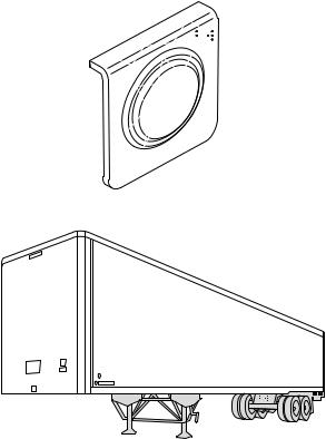
Trailer Mounted ABS Warning Light
Rules for the location, color, labeling, intensity and photometrics for external ABS warning lamps have been established by the National Highway Transportation Safety
Administration (NHTSA). These requirements were effective as of March 1, 1998.
Location
The lamp mounting location shall be near the left side rear of the trailer, no closer than 150 mm (5.9 inches) and not more than 600 mm (23.6 inches) from the rear red side marker indicator lamp. (Refer to Figure 22.) On a converter dolly, the lamp mounting location shall be on a permanent structure of the dolly at least 375 mm (14 inches) above the road surface.
Color and Labeling
The malfunction indicator lamp must be yellow in color and identified with the letters “ABS” to distinguish the lamp from other yellow side markers. The letters may be on the lens, on the lens housing, or on the trailer itself, near the lamp.
Intensity and Photometric Requirements
The external ABS malfunction indicator lamp must conform to SAE-J592 JUN92. Trailers shall use a combination clearance/side marker lamps marked with a “PC” or “P2”. These lamps offer a widely diffused beam pattern throughout a full 180-degree left and right range.
ABS
2
General Air Brake Requirements
Basic design requirements for trailer air brake systems are set forth in FMVSS-121. FMVSS-121 covers requirements for new construction. Once put into operation, the trailer’s brake systems must be maintained in accord with the following FHWA/OMC standards.
•FMCSR 393 - Covers required equipment
•FMCSR 396 - Covers inspection and repair
Air Timing Requirements
FMVSS-121 specifies the maximum times that are permitted for application and release of brake chamber pressure. Refer to Figure 2. ABS equipped trailers must meet the same air timing requirements as prior, non-ABS equipped trailers.
Reservoirs
Trailers must be equipped with air reservoirs that provide a volume of air eight times that of the service brake chambers.
For example: a type 30 air chamber has an effective surface area of 30 sq. in. For short stroke type 30 air chambers, the volume is typically 89 CID. For a typical two axle trailer, the minimum required volume is therefore 2848 CID.
Reservoir size requirements for non-ABS and ABS equipped systems are the same.
Air Consumption
During ABS activation there is a loss of reservoir pressure. There are no specific requirements limiting air consumption in the U.S. (In Europe Regulation R13 states specific limitations). ABS manufacturers take air consumption into account when developing and evaluating ABS control algorithms. There has been no need to change reservoir size requirements as a result of the ABS mandate.
Vehicle Classification |
Application Time (seconds) |
Release Time (seconds) |
||
|
|
|
|
|
|
From pedal |
Pedal movement |
From pedal |
From movement |
|
movement |
to reach 60 PSI |
movement to |
of the pedal until |
|
for chambers |
at 50 cu. Res |
reach 5 PSI |
50 cu. in. reservoir |
|
to reach 60 PSI |
at gladhand |
(w/95 PSI initial |
reaches 5 PSI |
|
|
|
chamber pressure) |
(With 95 PSI initial |
|
|
|
|
chamber pressure) |
Tractors, Trailers and Buses |
.45 |
.35 |
.55 |
.75 |
Towing Trailer |
.50 |
.50 |
1.00 |
1.00 |
Converter Dolly |
.55 |
.55 |
1.10 |
1.10 |
Single Trailer |
.60 |
— |
1.20 |
— |
|
|
|
|
|
Note: A 50 cubic inch reservoir is used to simulate the towed trailer volume at the gladhands of towing units. |
|
|||
|
|
|
|
|
FIGURE 2 - Air Timing Requirements Chart |
|
|
|
|
3
Brake Priority Options
In prior years, there were requirements for a protected reservoir, separate from the main reservoir. The purpose of the protected reservoir was to hold off the spring brakes in the event of a failure of the service brake system.
In 1994, FMVSS-121 was revised to allow other approaches to reservoir management. The protected reservoir approach, although not required, is still acceptable. Conventional trailers are designed for either:
•Spring Brake Priority or
•Service Brake Priority.
Spring Brake Priority–The advantage of spring brake priority is that the parking brakes (spring brake) can be released quickly to permit moving the trailer at start up. However, spring brake priority systems have failure modes under which the parking brakes can be released and the vehicle operated without functional service brakes.
Service Brake Priority–The advantage of the service brake priority system is that it assures that the service brakes have adequate air pressure available to them before release of the spring brakes is allowed. However, service brake priority systems require more time to bring a vehicle up to operational level.
The Bendix® A-18™ trailer ABS system is compatible with both Spring Brake Priority and Service Brake Priority systems and does not require special installation procedures. A number of spring brake control valves are suitable for meeting current requirements. Bendix offers spring brake valves suitable for a range of applications.
|
TEV |
|
STEV |
|
|
|
|
1/4" Supply Port |
|
|
1/4" |
|
|
|
|
Supply Port |
|
1/4" |
|
|
1/4" |
3/4" |
||
|
Control |
Control |
||
|
Reservoir |
|||
3/4" |
Port |
Port |
||
Port |
||||
Reservoir |
|
|
||
|
|
|
||
Port |
|
|
|
|
3/8" |
|
3/8" |
|
3/8" |
3/8" |
Delivery |
||
Delivery |
||||
Ports |
||||
Delivery Ports |
Delivery Ports |
|||
Ports |
||||
|
||||
|
|
|
||
FIGURE 3 - Spring Brake Control Valves |
|
|
|
4
ABS PERFORMANCE CHARACTERISTICS
Routine Braking
During routine braking operations, there is no indication of excessive wheel slip. The electronic control unit interprets this condition as normal and ABS remains inactive.
ABS Controlled Braking
The control unit continuously monitors all available wheel speed sensors. Data from the sensors is used to calculate values of wheel speed and wheel slip and to make a best estimate of the true vehicle speed. This data allows the control unit to detect impending wheel lock and to hold the wheel slip at an optimum value to maximize braking effectiveness. The best possible vehicle stability is assured while stopping distance is minimized.
Control is accomplished by operation of relay based modulator valves. The control unit makes a new assessment of conditions and updates the control signal to the modulator valves at a rate of approximately 100 times per second.
Under normal (non-ABS) conditions, trailer ABS relay valves operate exactly like conventional mechanical relay valves. (Refer to Figures 11 through 14.) During ABS operation, the control unit operates the valves to override the supply of air to the chambers. During an ABS release, supply air is held off while the chambers are vented to the atmosphere. In hold mode, supply air is blocked and chamber air is held constant. When required, air is applied to the chamber at a controlled rate by modulating the hold side of the valve.
The antilock system does not apply additional braking power. Rather, it controls air pressure to release and hold brake torque, thereby increasing a vehicle’s capacity for quick, straight stops. With ABS installed, vehicle operation is safer, resulting in improved protection of driver, cargo and equipment.
ABS Component Function
Figure 4 shows an overview of the operation of the Bendix® A-18™ trailer ABS system.
Speed sensors (1) monitor wheel rotation and provide information (2) on wheel rotation to the central electronic control unit.
The Electronic Control Unit (3) receives the sensor signal, interprets the pulse information, and constantly calculates the relationship of speed, acceleration, and deceleration. A control signal (4) is sent to the ABS relay valve (5), which then controls the pressure to the air chambers.
System Designs
When operating on high traction surfaces with a loaded vehicle, there is little difference between types of ABS control. Performance differences appear when vehicles are lightly loaded and operating on variable and poor traction surfaces. Examples of poor traction surfaces are ice and combinations of ice, snow and asphalt. Operating a vehicle in a curve highlights differences in stability between various systems.
ABS system designs provide compromises between stability and stopping distance while addressing cost, complexity and reliability issues.
1
Speed sensors |
|
monitor wheel |
|
rotation |
2 |
|
Speed signal |
|
to ECU |
5
Braking force remains at optimum level
Res. |
3 |
|
|
|
|
|
|
ECU interprets |
|
|
|
|
|
|
|
|
|
|
|
|
|
|
|
|
|
speed signals |
|
|
4 |
|
and activates valves |
|
Hold and release solenoids control air pressure in the brake chambers
FIGURE 4 - Overview of Trailer ABS Operation
5
Independent Regulation
The most obvious control concept is independent wheel control. In this case a single sensor controls a valve that operates the brakes at one wheel site. Individual control makes the best trade off between stability and stopping distance. However, these systems have greater complexity and higher cost with potentially lower reliability than less complex systems. In many cases it is necessary to control a single valve with inputs from two sensors.
Select Low
Select low systems monitor several wheels and controls them with a single valve. Control is based on the wheel that is at the lowest speed. Select low systems are very stable but sacrifice stopping distance on split coefficient surfaces. Modified select low systems incorporate a delay before releasing to reduce the bias slightly away from the low speed wheel.
Select High
Select high systems also monitor several wheels and control them with a single valve. Control is based on the wheel which is at the highest speed. Modified select high systems activate a release before the low speed wheel becomes severely locked. Select high systems generally have good stopping distances at the expense of stability. These systems may also have an increased risk of tire flat spotting.
Select Smart
Select Smart systems operate as select low systems when there is little difference in traction between wheel control sites. They operate as select high systems when there is a significant difference in traction between sites. These systems offer many of the advantages of individual control systems while using a simpler design and fewer components.
Bendix® A-18™ Trailer ABS Control Strategy
Select Smart is used for the most common applications. Select low is used on the standard system 4S/2M Axle Control configuration and is available as an option on the basic system.
TRAILER ABS CONFIGURATIONS
Application Recommendations
Refer to the chart on page 8 to determine a recommended ABS installation for your application.
Basic System (2S/1M)
The basic system includes two speed sensors and one modulator valve for direct control of one axle and indirect control of an additional axle. Other features of the basic system include one ECU connector and a single-pin diagnostic lead.
Standard System (2S/1M, 2S/2M and 4S/2M)
Bendix’s standard systems offer either two or four speed sensors and up to two modulator valves. Standard systems can directly control one or two axles and allow full diagnostics via J1587. The standard system may be configured in one of four ways to function as follows:
•2S/1M—This configuration uses two sensors and one modulator valve to directly control one axle and indirectly control an additional axle.
•2S/2M—This configuration uses two speed sensors and two modulator valves for direct control of one axle and indirect control of up to three additional axles.
•4S/2M—This configuration uses four speed sensors and two modulator valves for direct control of two axles and indirect control of up to two additional axles.
•4S/2M Axle Control—Special configuration for full trailers and widely spaced axles. This configuration uses the select low strategy.
Sensor Placement
When more than one wheel is controlled by a single valve, sensors should be mounted at the axle which tends to lock first. For spring suspensions this is usually the forward axle. For air suspensions this is usually the rear most axle.
Lift Axles
•Gen-4™ ABS: Sensor inputs “C” and “D” of the control unit may be used for lift axle wheel speed sensing.
•Gen-5™ ABS: Direct lift axle control is not available. Use indirect control.
Reading Configuration Codes
On Basic systems, the jumper method must be used to access the configuration. On Standard systems, access to configuration information can be achieved by any of the three methods:
•ServiceRanger diagnostic software on a PC
•Hand-held tester
•Jumper method.
For more information on accessing configuration codes, refer to Accessing Codes on page 30.
6

System Application Chart
Semi
Trailer
or
1st
Trailer
1st
2nd or 3rd Trailer
Trailer
Dolly
Trailer Type |
2S/1M |
|
2S/2M |
|
4S/2M Side Control |
|
4S/2M Axle Control |
|
(1) |
or |
(1) |
|
|
|
|
|
(1) |
or |
(1) |
or |
(1) |
|
|
|
|
|
|
|
(1) |
or |
(1) |
|
|
|
(1) |
or |
(1) |
|
|
|
|
|
|
|
(1) |
|
|
|
|
|
(1) |
|
|
|
|
|
|
|
(2) |
or |
(2) |
|
|
|
|
|
(2) |
or |
(2) |
|
|
|
|
|
(2) |
or |
(2) |
|
|
|
(2) |
and |
(1) |
or |
(2) |
or |
(2) |
|
(2) |
and |
(1) |
|
|
|
|
|
|
|
(1) |
or |
(1) |
|
|
|
|
|
(1) |
or |
(1) |
|
|
|
(1) |
or |
(1) |
or |
(1) |
|
|
|
(1) |
or |
(1) |
|
|
|
|
|
|
|
|
|
(1) |
or |
(1) |
|
|
|
(2) |
or |
(2) |
|
|
|
(1) |
|
|
|
|
|
|
|
(1) |
|
|
|
|
|
|
|
|
|
(1) |
|
|
|
|
FIGURE 5 - System Application Chart
7
Trailer ABS Component Overview
Bendix® A-18™ trailer ABS system includes the following components:
•Electronic Control Unit (ECU): The ECU monitors wheel speeds and controls the trailer ABS valves. It also diagnoses ABS malfunctions and stores failurespecific fault codes. The ECU is usually attached to a relay valve with a mounting bracket. The ECU may also be directly frame mounted. One ECU can monitor either two or four speed sensors and control either one or two relay valves. If necessary more than one ECU may be used on a single trailer.
•Relay Valve: This component regulates brake chamber air pressure. It houses the hold and release solenoids. Each relay valve can control either two or four brake chambers on an ABS equipped trailer. A relay valve can have the ECU mounted to it (valve A in the installation diagrams) or be a stand alone relay valve (valve B in the installation diagrams) that is controlled remotely by the ECU mounted on valve A.
•Trailer Mounted ABS Warning Lamp: This indicator lamp, located on the “Road Side” near the rear of the trailer, warns the driver of ABS malfunctions (steady “ON”). It is also capable of blinking diagnostic fault codes.
•Cab Mounted ABS Warning Lamp: This indicator lamp, located on the driver instrument panel, also warns the driver of ABS malfunctions. It is not capable of blinking diagnostic fault codes.
•Wheel End Speed Sensor and Tone Wheel: Single point variable reluctance (magnetic) sensor that generates an alternating current signal in response to the movement of teeth on a tone wheel. The signal is interpreted by the ECU to monitor wheel speed.
•Diagnostic Port Connector: The diagnostic port connector is an industry standard connector which is used to provide a connection to the J1587 diagnostic link. This connector also provides power and ground for diagnostic test equipment.
•Gladhand: The gladhands used on the ABS system are the same as those used on non-ABS trailers.
•Seven Way Main Electrical Connector: The seven way receptacle is the same as those used on non-ABS systems. This receptacle provides full-time power, backup power via the brake light switch and ground for the ABS electrical system.
•Optional ISO 3731 connector: This is a 7-pin connector similar to the J560 connector. The most noticeable difference is that the ground terminal has a gender opposite that of the other terminals. The primary use for ISO 3731 is for the lighting connections on European trailers. However, this connector is used to provide interface to trailer ABS in some U.S. applications. (In Europe another connector designated as ISO 7638 is used to provide interface to the trailer braking system.)
8
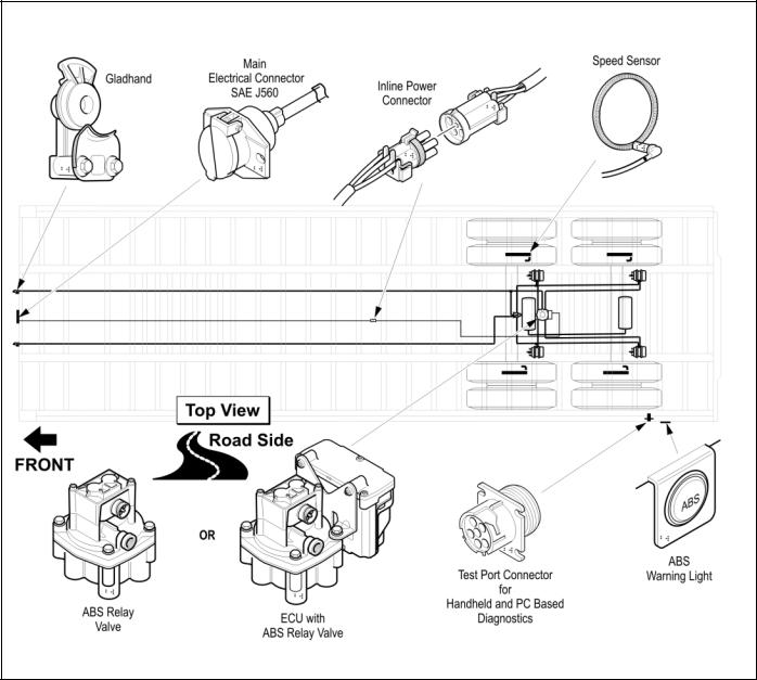
FIGURE 6 - ABS Trailer Components
9
Electronic Control Unit (ECU)
The Bendix® A-18™ ECU is the trailer ABS control center.
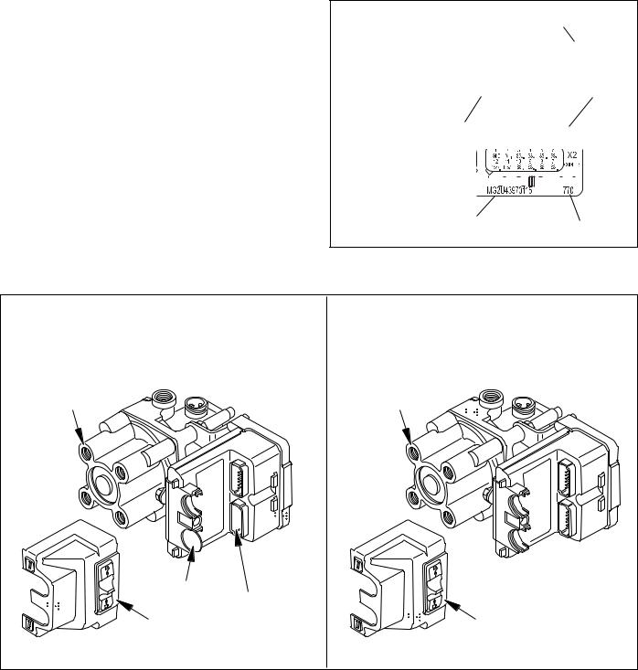
Identification
Identification information for the ECU is located on the connector pinout label (refer to Figure 7). The label is located under the ECU cover. Refer to the label for the:
•Part Number
•Serial Number
•Date Code.
Depending on configuration, the A-18™ trailer ABS system ECUs may be equipped with either one connector (basic system) or two connectors (standard system). Refer to Figure 8.
Bendix Part Number
Basic System |
|
|
|
Date Code |
||
Serial Number |
|
|
|
|||
|
|
|
|
|
||
|
|
|
|
|
|
|
|
|
|
|
|
|
|
|
|
|
|
|
|
|
|
|
|
|
|
|
|
|
|
|
|
|
|
|
Standard System |
Date Code |
|
Serial Number |
||
|
FIGURE 7 - Electronic Control Unit Identification Tags
BASIC |
STANDARD |
Relay Valve |
Relay Valve |
Plug |
|
|
Blank |
ECU Cover |
Connector |
ECU Cover |
FIGURE 8 - Trailer ABS ECU Configurations
10
Sensor A
Sensor B
Sensor C
Sensor D
Brake Light Power
Full Time Power
Inputs
+
X2-4
-X2-3
+
X2-6
-X2-5
+
X2-8
-X2-7
+
X2-10
-X2-9
X1-7
X1-6
X1-5
Inputs
Standard
Trailer
ECU
(2 Connectors)
Outputs
X1-10 |
|
|
|
Valve A |
||
|
|
|
||||
|
|
|
|
|||
|
Common |
|
|
|
|
|
|
|
|
|
|
||
X1-3 |
|
|
|
|
||
|
|
|
|
|||
Hold |
|
|
|
|
|
|
|
|
|
|
|
|
|
X1-4 |
|
|
|
|
|
|
|
|
|
|
|
|
|
|
|
|
|
|
|
|
X1-12 |
Release |
|
Valve B |
||||||||
Common |
|
||||||||||
|
|
|
|
|
|
|
|
|
|
|
|
|
|
|
|
|
|
|
|
|
|
|
|
X1-2 |
|
|
|
|
|
|
|
|
|
|
|
|
|
|
|
|
|
|
|
|
|
||
Hold |
|
|
|
|
|
|
|
|
|
|
|
|
|
|
|
|
|
|
|
|
|
|
|
|
|
|
|
|
|
|
|
|
|
|
|
|
|
|
|
|
|
|
|
|
|
|
|
X1-1 |
|
|
|
|
|
|
|
|
|
|
|
|
|
|
|
Trailer Mounted |
|||||||
|
|
|
|
|
|||||||
|
|
|
|
|
|||||||
|
|
|
|
|
Warning Light |
||||||
X1-9 |
|
|
|
|
|
|
|
|
|
|
|
|
|
|
|
|
|
|
|
|
|
|
|
|
|
|
|
|
|
|
|
|
|
|
|
|
|
|
|
|
|
|
|
|
|
|
|
|
|
|
|
|
|
|
|
|
|
|
|
X2-2
X2-11 |
J1587+ |
J1587 |
|
X2-12 |
Diagnostic Link |
|
|
X2-1 |
J1587 Gnd |
|
|
|
Diagnostic |
|
Switch |
Outputs |
|
Sensor A |
+ |
|
|
|
Release |
|||||||||||||||||||||
X1-1 |
|
X1-10 |
||||||||||||||||||||||||
|
|
|
|
|
|
|
|
|
|
|
|
|
|
|
|
|
Valve A |
|||||||||
|
|
|
|
|
|
|
|
|
|
|
|
|
|
|
|
|
|
|
|
|
||||||
|
|
|
|
|
|
|
|
|
- |
|
|
|
Common |
|
|
|
|
|
|
|
|
|
|
|||
|
|
|
|
|
|
|
|
|
|
|
|
|
|
|
|
|
|
|
|
|
|
|||||
|
|
|
|
|
|
|
|
|
|
|
|
|
|
|
|
|
|
|
|
|
|
|||||
|
|
|
|
|
|
|
|
|
X1-2 |
|
X1-3 |
|
|
|
|
|
|
|
|
|
|
|||||
|
|
|
|
|
|
|
|
|
|
|
|
|
|
|
|
|
|
|
|
|||||||
|
|
|
|
|
|
|
|
|
|
|
|
|
|
|
|
|
|
|||||||||
Sensor B |
+ |
|
|
|
Hold |
|
|
|
|
|
|
|
|
|
|
|||||||||||
X1-12 |
|
X1-4 |
|
|
|
|
|
|
|
|
|
|
||||||||||||||
|
|
|
|
|
|
|
|
|
|
Basic |
|
|
Trailer Mounted |
|||||||||||||
|
|
|
|
|
|
|
|
|
|
|
|
|
|
|
|
|||||||||||
|
|
|
|
|
|
|
|
|
|
|
|
|
|
|
|
|||||||||||
|
|
|
|
|
|
|
|
- |
|
Trailer |
|
|
|
Warning Light |
||||||||||||
|
|
|
|
X1-11 |
X1-8 |
|
|
|
|
|
|
|
|
|
|
|
|
|||||||||
|
|
|
|
|
|
|
|
|
|
|
|
|
|
|
||||||||||||
Brake Light Power |
|
|
|
|
|
|
|
|
|
|
|
ECU |
|
|
|
|
|
|
|
|
|
|
|
|
|
|
|
|
|
|
|
|
|
|
|
|
X1-7 |
(1 Connector) |
|
|
|
|
|
|
|
|
|
|
|
|
|
||
|
|
|
|
|
|
|
|
|
|
|
|
|
|
|
|
|
|
|
|
|
|
|
||||
|
|
|
|
|
|
|
|
|
|
|
|
|
|
|
|
|
|
|
|
|
|
|
||||
Full Time Power |
|
|
|
|
|
|
|
|
|
|
|
|
|
|
|
Diagnostic Plug |
||||||||||
|
|
|
|
|
|
|
|
|
|
|
|
|
|
|
||||||||||||
|
|
|
|
|
|
|
|
|
|
X1-6 |
|
X1-9 |
|
|
|
|||||||||||
|
|
|
|
|
|
|
|
|
|
|
|
|
|
|||||||||||||
|
|
|
|
|
|
|
|
|
|
|
|
|
|
|
|
|||||||||||
|
|
|
|
|
|
|
|
|
|
|
|
|
|
|
|
|
|
|
|
|
|
|
|
|
|
|
|
|
|
|
|
|
|
|
|
|
|
|
|
|
|
|
|
|
|
|
|
|
|
|
|
|
|
|
|
|
|
|
|
|
|
|
|
|
|
|
|
|
|
|
|
|
|
|
|
|
|
|
|
|
|
|
|
|
|
|
|
|
|
|
|
|
X1-5 |
|
|
|
|
|
|
|
|
|
|
|
|
|
|
|
|
|
|
|
|
|
|
|
|
|
|
|
|
|
|
|
|
|
|
|
|
|
|
|
|
|
|
|
|
|
|
|
|
|
|
|
|
|
|
|
|
|
|
|
|
|
|
|
|
|
|
|
|
|
|
|
|
|
|
|
|
|
|
|
|
|
|
|
|
|
|
|
|
|
|
|
|
|
|
|
|
|
|
|
|
|
|
|
|
|
|
|
|
|
|
|
|
|
|
|
|
|
|
|
|
|
|
|
|
|
|
|
|
|
|
|
|
|
|
|
|
|
|
|
|
|
|
|
|
|
|
|
|
|
|
|
|
|
|
|
|
|
|
|
|
|
|
|
|
|
|
|
|
|
|
|
|
|
|
|
|
FIGURE 9 - Standard and Basic ECU Block Diagrams |
|
|
|
|
|
|
|
|
|
|
|
|
|
|||||||||||||
11
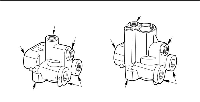
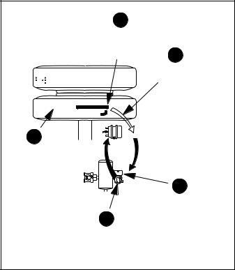
Relay Valve
The trailer ABS relay valve controls air pressure to individual brake assemblies, and functions as a standard relay valve when there are no ABS control signals. Depending on the particular ABS configuration, a system may utilize one or two relay valves. See Figure 10.
Each relay valve contains two solenoids for air control. The hold solenoid maintains air pressure; the release solenoid removes pressure from the brake. The Electronic Control Unit signals the relay valve(s) for air hold and release by activating the appropriate solenoid.
Each relay valve has a three-pin terminal for connection to the Electronic Control Unit.
Delivery Ports
Both 2-port and 4-port versions of the relay valve are available. These are all tapped for 3/8 NPT fittings.
Crack Pressure
Standard valves are available with 4.0 PSI ±0.5 PSI crack pressure. Other crack pressures can be provided. For example, 6.0 PSI valves may be used with wedge brakes.
Bracket, Valve, ECU combinations
Various combinations of mounting brackets, ECUs and valves are available preassembled to facilitate system installation on a variety of vehicles. Refer to the Bendix® A-18™ trailer ABS Illustrated Parts List for further information.
Port Orientation
If necessary, the control and supply ports of the valve can be reoriented with respect to each other. Remove the four assembly bolts. Rotate top with respect to bottom as required. Use care to maintain cleanliness of valve interior. Retorque bolts to 10.0 lb-ft (13.6 N•m). Do not exceed 12.0 lb-ft (16.3 N•m).
Pipe Fitting Torques
Refer to the following torque specifications when installing pipe nipples. Torques are for NPT threads with thread sealant applied. Do not use thread tape. Contamination by thread tape can cause component failure.
Tighten pipe nipples as follows:
•With Thread Sealant - Finger tight plus 1 1/2 turns
•Without Thread Sealant - Finger tight plus 2 turns
Clamping
A fixture may be necessary to hold the relay valve when reorienting ports or when attaching fittings. If a vise is used, there is a potential danger of distorting the barrel and piston within the valve rendering the valve inoperative. It is recommended that a fixture be used that avoids the potential for stressing the valve.
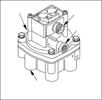
3/4" Supply Port |
Three-Pin |
|
ECU Connector |
||
|
||
|
3/8" Control Port |
Out
(3/8" Delivery Port to Brake Chamber)
Figure 10 - Relay Valve
WARNING! PLEASE READ AND FOLLOW THESE INSTRUCTIONS TO AVOID PERSONAL INJURY OR DEATH:
When working on or around a vehicle, the following general precautions should be observed at all times.
1.Park the vehicle on a level surface, apply the parking brakes, and always block the wheels. Always wear safety glasses.
2.Stop the engine and remove ignition key when working under or around the vehicle. When working in the engine compartment, the engine should be shut off and the ignition key should be removed. Where circumstances require that the engine be in operation, EXTREME CAUTION should be used to prevent personal injury resulting from contact with moving, rotating, leaking, heated or electrically charged components.
3.Do not attempt to install, remove, disassemble or assemble a component until you have read and thoroughly understand the recommended procedures. Use only the proper tools and observe all precautions pertaining to use of those tools.
4.If the work is being performed on the vehicle’s air brake system, or any auxiliary pressurized air systems, make certain to drain the air pressure from all reservoirs before beginning ANY work on the vehicle. If the vehicle is equipped with an AD-IS™ air dryer system or a dryer reservoir module, be sure to drain the purge reservoir.
5.Following the vehicle manufacturer ’s recommended procedures, deactivate the electrical system in a manner that safely removes all electrical power from the vehicle.
12
 Loading...