


®
![]() SD-03-826
SD-03-826
Bendix® E-12™ & E-15™ Dual Brake Valve
TREADLE
UPPER |
MOUNTING |
|
|
||
PLATE |
|
|
|
||
BODY |
|
|
|
|
|
ASSEMBLY |
PRIMARY |
|
|
||
|
|
|
|||
PRIMARY |
SUPPLY |
PRIMARY |
|||
SUP-1 |
) |
DELIVERY |
|||
DELIVERY |
( 11 |
( DEL21-1 ) |
|||
( DEL-1 ) |
|
|
|||
21 |
|
|
|
|
|
|
PRIMARY |
SECONDARY |
|||
SECONDARY |
SUPPLY |
||||
SUP-2 |
|
DELIVERY |
|||
DELIVERY |
|
||||
( 12 |
) |
DEL-2 |
) |
||
( DEL-2 ) |
|||||
|
|
( 22 |
|||
22 |
|
|
|
|
|
LOWER |
|
|
|
|
|
BODY |
EXHAUST |
|
|
|
|
ASSEMBLY |
|
|
|
|
|
|
|
|
|
|
|
FIGURE 1 - E-12™ AND E-15™ |
DUAL BRAKE VALVES |
|
|
|
|
DESCRIPTION
The E-12™ and E-15™ dual brake valves are floor mounted, treadle operated type brake valves with two separate supply and delivery circuits for service and secondary braking. The separation of circuits provides the driver with a graduated control for applying and releasing the vehicle brakes.
The E-12™ and E-15™ brake valves are similar in design with the exception of the rubber spring (9) and spring retainer (7) located in the upper body. The rubber spring which is used in the E-12™ brake valve alters the performance of the valve such that the primary circuit delivers full reservoir pressure to the spring brakes with less treadle travel than that of the E-15™ brake valve. See Figure 2 for delivery pressure versus treadle travel diagram. The greater treadle travel of the E-15™ brake valve yields a more gradual delivery of air to the spring brakes resulting in a less sensitive “feel” to the driver when a brake application is made. This characteristic makes the E-15™ brake valve more adaptable to transit vehicle applications where smooth brake applications contribute to passenger comfort.
The E-12™ and E-15™ valves are designed such that the treadle does not sit in an upright position until the air system is built up to full reservoir pressure. The supply pressure moves the primary piston upward transmitting a mechanical force to the spring retainer and plunger of the treadle assembly, causing the treadle to move upright.
|
|
E-12™ DUAL |
|
|
|
E-15™ DUAL |
|
||||||
|
|
|
|
|
|
||||||||
|
|
BRAKE VALVE |
|
|
BRAKE VALVE |
|
|||||||
|
|
|
|
|
|
|
|
|
|
|
|
|
|
PRIMARYDELIVERY (PSI) |
|
|
|
|
|
|
PRIMARYDELIVERY (PSI) |
|
|
|
|
|
|
|
|
|
|
|
|
|
|
|
|
|
|||
|
|
|
|
|
|
|
|
|
|
|
|||
|
|
|
|
|
|
|
|
|
|
|
|||
|
↑ |
|
|
|
|
↑ |
|
|
|
|
|||
|
|
|
|
|
|
|
|
|
|
|
|
||
|
|
|
|
|
|
|
|
|
|
|
|
|
|
|
TREADLE TRAVEL |
|
|
TREADLE TRAVEL |
|
||||||||
|
|
|
|
|
|
|
|
|
|
|
|
|
|
|
|
|
|
|
|
|
|
|
|
|
|
|
|
FIGURE 2 - TREADLE TRAVEL VERSUS DELIVERY
PRESSURE
1
|
|
|
|
26 |
|
|
|
|
|
|
30 |
|
|
|
|
|
|
|
|
31 |
|
|
|
|
|
|
32 |
|
|
27 |
|
|
|
|
|
28 |
|
|
|
|
|
7 |
29 |
|
|
|
|
|
|
|
|
|
|
|
|
6 |
|
|
|
|
|
1 |
8 |
|
|
|
|
|
|
|
|
|
|
|
2 |
|
9 |
|
|
|
23 |
4 3 |
|
15 |
|
|
|
|
||
|
|
|
21 22 |
|
4 |
|
14 |
|
|
|
|
|
|
13 |
|
|
|
|
|
5 |
|
|
|
20 UPPER BODY |
|||
12 |
|
|
|
|||
11 |
|
|
|
|
|
18 |
|
|
|
|
|
|
|
10 |
|
|
|
|
|
19 |
17 |
|
|
|
|
|
LOWER BODY |
12 |
|
|
|
|
|
10 |
|
|
|
|
|
|
|
13 |
|
|
|
11 |
||
|
14 |
15 |
25 |
24 |
|
|
|
|
|
|
|
|
|
FIGURE 3 - E-12™ DUAL BRAKE VALVE CROSS
SECTIONAL VIEW
The circuits in the E-12™ /E-15™ valves are identified as follows: The no. 1 or primary circuit is that portion of the valve between the primary piston (2) and the secondary piston (18); the no. 2 or secondary circuit portion consists of the area between the secondary piston and the exhaust cavity.
The supply, delivery and exhaust ports of the E-12™ /E-15™ brake valves are identified by designations cast into the valve body adjacent to their associated port. (See Figure 1). The primary supply and delivery ports are located in the upper body portion while the secondary supply and delivery ports are located in the lower body portion of the valve.
The primary circuit of the valve is similar in operation to a standard single-circuit air brake valve and under normal operating conditions the secondary circuit is similar in operation to a relay valve.
Both the primary and secondary circuits of the brake valve use a common exhaust protected by an exhaust diaphragm.
OPERATION
APPLYING: NORMAL OPERATION-PRIMARY CIRCUIT PORTION
When the brake treadle (26) is depressed, the plunger (27) exerts a force on the spring retainer (7), graduation spring
(8) and primary piston (2). The primary piston, which contains the exhaust valve seat closes the primary circuit exhaust valve. As the exhaust valve closes the inlet valve for the primary circuit moves off of its seat allowing the air from the supply port of the primary circuit to flow out the delivery port of the same circuit.
|
MV-3™ |
TP-5 |
™ |
TRACTOR |
|
|
MODULE |
|
|
||
|
PROTECTION |
|
|||
|
|
|
|||
|
TRAILER |
|
|
|
SPRING |
|
CONTROL |
|
|
|
|
|
|
|
|
BRAKES |
|
|
VALVE |
|
|
SLACK |
|
|
|
|
|
||
|
BRAKE |
|
|
ADJUSTER |
|
|
|
|
|
|
|
SLACK |
CHAMBER |
|
|
|
|
|
|
|
|
|
|
ADJUSTER |
|
|
|
|
|
|
DUAL BRAKE |
|
|
|
|
|
VALVE |
|
|
|
QUICK |
|
|
|
|
|
|
|
|
|
|
DOUBLE |
RELEASE |
|
|
|
|
VALVE |
|
|
|
|
|
CHECK |
|
|
|
|
|
|
|
|
AIR DRYER |
|
|
VALVE |
|
|
|
|
|
|
|
|
|
|
|
|
BP-R1™ |
|
|
|
|
|
BOBTAIL |
|
|
|
|
|
PROPORTIONING |
|
|
|
|
|
VALVE |
|
SUPPLY |
|
|
|
|
|
RESERVOIR |
|
|
|
|
|
COMPRESSOR |
#1 SERVICE |
|
#2 SERVICE |
|
|
|
|
|
||
|
|
RESERVOIR |
|
RESERVOIR |
|
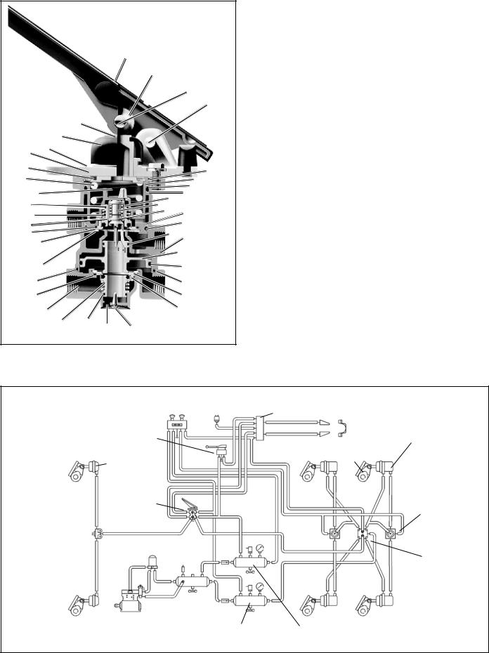
FIGURE 4 - TYPICAL PIPING SCHEMATIC
2

PLUNGER |
|
2 |
FORCE |
7 |
|
8 |
SUP-1 |
|
|
DEL-1 |
|
18 |
SUP-2 |
DEL-2 |
|
|
|
EXHAUST |
FIGURE 5 - APPLYING - NORMAL OPERATION
APPLYING: NORMAL OPERATION-
SECONDARY CIRCUIT PORTION
The relay piston moves down with the primary piston and closes the secondary circuit exhaust. When the inlet valve in the primary portion of the valve is moved off its seat, air passes through the bleed passage in the lower portion of the upper body and enters the relay piston cavity. The air moves the relay piston (18) downward and opens the secondary inlet valve, allowing the air from the secondary supply to flow out the delivery port of the same circuit.
APPLYING: LOSS OF AIR IN THE PRIMARY CIRCUIT
If air is lost in the primary circuit, the valve will function as follows: As the brake pedal is depressed and no air pressure is present in the primary circuit, the primary piston (2) will mechanically move the relay piston closing the secondary exhaust and opening the inlet valve of the same circuit allowing air flow from the secondary supply to its associated delivery port.
APPLYING: LOSS OF AIR IN THE SECONDARY CIRCUIT
If the air is lost in the secondary circuit, the primary circuit will function as described above under Normal Operation: Primary circuit portion.
PLUNGER |
|
FORCE |
2 |
SUP-1
DEL-1
DEL-2
SUP-2
EXHAUST
FIGURE 6 - APPLYING - FAILURE IN THE PRIMARY
CIRCUIT
BALANCED: PRIMARY CIRCUIT PORTION
When the primary delivery pressure acting upon the primary piston (2), equals the resultant mechanical force of the brake treadle application, the primary piston will close preventing further air flow from the supply to the delivery port of the brake valve. The exhaust valve remains closed preventing the escape of air through the exhaust port.
PLUNGER |
|
2 |
FORCE |
7 |
|
|
|
8 |
SUP-1 |
|
|
|
|
DEL-1 |
|
|
18 |
SUP-2 |
|
DEL-2 |
EXHAUST
FIGURE 7 - APPLYING - FAILURE IN THE SECONDARY
CIRCUIT
3
 Loading...