


®
SD-03-4650
Bendix® TR-2™ , TR-3™ & TR-4™ Inversion Valves
|
|
|
CAP NUT |
|
SUPPLY PORT |
SEAL RING |
|
|
|
INLET & EXHAUST |
MOUNTING NUT |
|
|
VALVE SPRING |
|
|
|
|
& LOCKWASHER |
|
|
|
|
|
|
|
INLET & EXHAUST |
|
|
|
VALVE |
DELIVERY PORT (2) |
|
BODY |
|
|
|
PISTON GROMMET |
|
|
|
|
|
CONTROL PORT (3) |
|
|
(SMALL) |
|
|
|
|
|
|
PISTON SPRINGS |
PISTON |
|
|
|
|
|
|
|
PISTON GROMMET |
|
|
RETAINER RING |
(LARGE) |
|
|
COVER PLATE |
|
|
|
|
|
|
EXHAUST |
EXHAUST |
|
|
|
DIAPHRAGM WASHER |
|
|
|
DIAPHRAGM |
|
|
|
|
|
|
|
|
CAP SCREW |
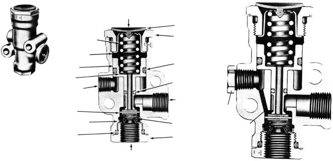
FIGURE 1 - TR-2™ INVERSION VALVE
DESCRIPTION
GENERAL
The TR-2™ & TR-3™ valves are normally open pilot-operated, inverting, on-off, two-way valves. The TR-4™ valve is lever operated. With normal operating pressure at both supply and control ports, the delivery port will be exhausted to atmosphere. As control pressure is reduced to the point that the piston return spring or springs overcomes the force on the control piston, the valve will deliver full supply pressure at the delivery port.
TR-2™ INVERSION VALVE
Referring to Figure 1, the TR-2™ valve was used primarily in early DD-3™ Safety Actuator control systems to apply air pressure to the emergency diaphragm of the DD-3™ actuator’s from a protected reservoir as control pressure is released from the lock mechanism. The TR-2™ valve is available in 11/4" bulk head mount only.
TR-3™ INVERSION VALVE
Referring to Figure 2, the TR-3™ valve is similar in function to the TR-2™ valve, but with a die cast body. Referring to Figure 3, some TR-3™ valve’s have an internal passage in the body connecting supply pressure to control. The external control port is permanently plugged in such valves.
TR-4™ INVERSION VALVE
Referring to Figure 4, the TR-4™ valve is a TR-3™ valve with the internal passage connecting supply and control plus a manual lever control which permits the valve to be locked in the open position.
OPERATION
TR-2™ & TR-3™ INVERSION VALVES
When sufficient air pressure is present in the control cavity to overcome the setting of the piston return spring, the piston is held away from the inlet valve which is held closed by the inlet valve return spring. The delivery lines are vented to atmosphere through the hollow exhaust stem of the piston. When air pressure in the control cavity falls to a
1
|
EXHAUST |
|
|
DIAPHRAGM |
|
PISTON SPRING |
EXHAUST |
|
NUT |
|
|
|
|
|
DIAPHRAGM |
|
|
RETAINER |
O-RING |
|
PISTON |
|
|
|
|
|
SHIM |
O-RING |
|
1/8” P.T. |
|
|
|
|
|
CONTROL |
1/4” P.T. |
|
INLET & |
|
|
DELIVERY |
PIPE |
|
EXHAUST |
|
|
VALVE |
VALVE |
PLUG |
VALVE STOP |
|
|
SPRING |
|
|
|
INTERNAL |
|
O-RING |
|
|
CAP |
PASSAGE |
|
|
1/4” P.T. SUPPLY |
|
|
|
|
FIGURE 2 - TR-3™ INVERSION VALVE
predetermined pressure or is vented from the control cavity, the piston spring forces the piston against the inlet valve closing the exhaust passage in the hollow piston stem. Further travel of the piston opens the inlet valve allowing the passage of air past the open inlet valve and out the delivery port.
The TR-3™ valve with the internal control passage functions the same as above except that the control pressure is always the same as the supply pressure. Consequently, as supply pressure builds up, when the pressure is great enough to overcome the piston return spring, the delivery pressure will be vented out the exhaust. On descending supply/control pressure, as the piston return spring overcomes the control pressure the valve will deliver the remaining supply pressure at the delivery port.
TR-4™ INVERSION VALVE
The TR-4™ valve provides the same functions as the internal passaged TR-3™ valve except the lever override gives the operator the option of locking the valve in the open or delivery position.
MOUNTING LOCATION
Care should be given to assure proper mounting location of the valve with the exhaust pointed downward, mounted high on the frame rail, and away from road spray and debris. Unprotected or exposed exhaust ports can allow migration of road contaminants into the valve, which may cause accelerated wear or unintended operation.
FIGURE 3 - TR-3™ INVERSION VALVE
INTERNAL BLEED CONTROL
PREVENTIVE MAINTENANCE
Important: Review the Bendix Warranty Policy before performing any intrusive maintenance procedures.Awarranty may be voided if intrusive maintenance is performed during the warranty period.
No two vehicles operate under identical conditions, as a result, maintenance intervals may vary. Experience is a valuable guide in determining the best maintenance interval for air brake system components. At a minimum, the inversion valves should be inspected every 6 months or 1500 operating hours, whichever comes first, for proper operation. Should the inversion valves not meet the elements of the operational tests noted in this document, further investigation and service of the valve may be required.
OPERATING AND LEAKAGE TESTS
NOTE: The following checks should be made with two calibrated gauges or two gauges known to be accurate. Depending upon installation, it may be easier or necessary to completely remove the valve to test properly.
Install one test gauge in a common control and supply line; install the other gauge in the delivery port. Gradually apply pressure to the common supply and control line. On ascending pressure, note at what pressure exhaust occurs and compare with vehicle manual. With air pressure present in supply and control port, apply a soap solution around the supply port cap nut. No leakage is permitted. Apply soap solution to the delivery and exhaust ports. Leakage should not exceed 100 SCCM or a 1" bubble in not less than 5 seconds. Excessive leakage would indicate a faulty o-ring or inlet valve. Operate the manual control of the TR-4™ valve and note that delivery and exhaust occur promptly.
2
 Loading...