


®
SD-13-4746
Bendix® Gen 4™ and Gen 5™ ABS for Trucks, Tractors, and Buses
Cab-Mounted Models |
Frame-Mounted Model |
|
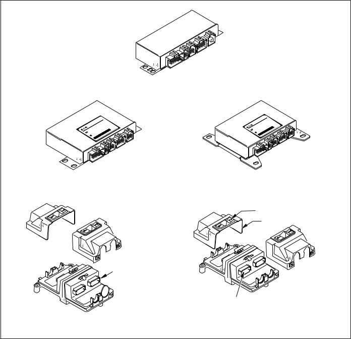
FIGURE 1 - Bendix® ABS Controller Assemblies
GEN 4™ AND GEN 5™ ABS INTRODUCTION
This manual describes both the cab mount and the frame mount versions of the Bendix® Gen 4™ and Gen 5™ Antilock Brake System/Automatic Traction Control (ABS/ATC) systems.
Both cab and frame mount versions are designed for:
•Tractors
•Trucks
•Buses and
•Motor Coaches and
•RVs.
This manual covers:
•ABS/ATC Operation
•System Components
•Service Procedures
•Diagnosis and
•Troubleshooting Procedures.
For information on disassembly, installation, and service of related axle and brake components, refer to their individual Bendix Service Manuals.
For assistance in your area call Bendix at 1-800-247-2725 or RoadRanger® at 1-800-826-4357.
These ABS controllers and systems were originally marketed by Eaton Corporation under the Eaton® brand name. For more information contact Bendix, your local authorized Bendix dealer, or RoadRanger® .
Document Revision Level
This document is subject to revision.
For updates, please visit www.bendix.com.
Table of Contents |
|
ABS Operation . . . . . . . . . . . . . . . . . . . . . . . . . . . . . . |
. 2 |
ABS Component Function . . . . . . . . . . . . . . . . . . . . . |
. 3 |
ABS Indicator Lamp . . . . . . . . . . . . . . . . . . . . . . . . . . . |
3 |
ABS Trailer Indicator Lamp . . . . . . . . . . . . . . . . . . . . . |
3 |
Automatic Traction Control (ATC) System . . . . . . . . . . |
4 |
Component Overview . . . . . . . . . . . . . . . . . . . . . . . . . |
5 |
Electronic Control Units (ECUs) . . . . . . . . . . . . . . . . . |
7 |
ABS Valves . . . . . . . . . . . . . . . . . . . . . . . . . . . . . . . . . |
9 |
Modulator Valve Operation Modes . . . . . . . . . . . . . . . |
10 |
Optional Front Axle Modules . . . . . . . . . . . . . . . . . . . |
11 |
Diagnostics . . . . . . . . . . . . . . . . . . . . . . . . . . . . . . . . |
13 |
Troubleshooting Procedures . . . . . . . . . . . . . . . . . . . |
13 |
System Configurations . . . . . . . . . . . . . . . . . . . . . . . |
15 |
ServiceRanger PC Software . . . . . . . . . . . . . . . . . . . |
16 |
Test Equipment . . . . . . . . . . . . . . . . . . . . . . . . . . . . . |
16 |
Reading Configuration Codes . . . . . . . . . . . . . . . . . . |
18 |
Retrieving Diagnostic Trouble Codes . . . . . . . . . . . . . |
18 |
Clearing Diagnostic Trouble Codes and/or System |
|
Configuration . . . . . . . . . . . . . . . . . . . . . . . . . . . . . |
20 |
Disabling ATC for Dyno Testing . . . . . . . . . . . . . . . . . |
20 |
Speed Sensor Troubleshooting . . . . . . . . . . . . . . . . . |
25 |
The 17•12 Sensor Memory Diagnostic Trouble Code |
26 |
Wheel End Speed Sensor Repair . . . . . . . . . . . . . . . |
28 |
Pressure Modulator Valve (PMV) Troubleshooting . . |
30 |
ABS Modulator Valve . . . . . . . . . . . . . . . . . . . . . . . . . |
33 |
Automatic Traction Control (ATC) Valve |
|
Troubleshooting . . . . . . . . . . . . . . . . . . . . . . . . . . . |
34 |
Performance Test of the Relay Valve . . . . . . . . . . . . . |
34 |
ATC Valve Removal . . . . . . . . . . . . . . . . . . . . . . . . . . |
36 |
Cab Mount ECU Pin Identification . . . . . . . . . . . . . . . |
39 |
Frame Mount ECU Pin Identification . . . . . . . . . . . . . |
43 |
Eaton® , RoadRanger® , and ServiceRanger® are registered |
|
trademarks of Eaton Corporation. |
|
1
ANTILOCK BRAKING SYSTEM (ABS) |
When inactive, the pressure modulator valves provide |
||||||||||||
ABS-controlled braking ensures optimum vehicle stability |
straight-through-passages for supply air to the brake |
||||||||||||
chambers. During ABS operation (an ABS “event”), the |
|||||||||||||
while minimizing the stopping distance. During vehicle |
|||||||||||||
control unit operates the valves to override the supply of |
|||||||||||||
operation, the ABS Electronic Control Unit (ECU) |
|||||||||||||
air to the chambers. During an ABS release, supply air is |
|||||||||||||
continuously monitors all wheel speed sensors. Data input |
|||||||||||||
held off while the chambers are vented to the atmosphere. |
|||||||||||||
from the wheel speed sensors allows the ECU to: |
|||||||||||||
In hold mode, supply air is held off and chamber air is held |
|||||||||||||
• Detect impending wheel lock. |
|
|
|
||||||||||
|
|
|
constant. When required, air is applied to the chamber at |
||||||||||
|
|
|
|
|
|||||||||
• Maintain optimum wheel slip during braking. |
a controlled rate by modulating the hold side of the |
||||||||||||
• Maximize vehicle stability while maintaining braking |
modulator valve. |
||||||||||||
effectiveness. |
|
|
|
The ABS system itself does not apply additional braking |
|||||||||
ABS Operation |
|
|
|
power. Rather, the purpose of ABS is to limit brake torque |
|||||||||
|
|
|
to prevent locking that results in loss of lateral stability and |
||||||||||
The ABS controls braking by operating the Pressure |
|||||||||||||
increased stopping distances. Cautious driving practices |
|||||||||||||
Modulator Valves. The ECU makes a new assessment of |
such as maintaining adequate distances from the vehicle |
||||||||||||
conditions and updates the control signal to the pressure |
ahead are still essential to safe vehicle operation. |
||||||||||||
modulator valves at the rate of 100 times per second. |
|
|
|
|
|
|
|
|
|||||
|
|
|
|
|
|
|
|
|
|
|
|
|
|
|
|
1 |
|
|
|
|
|
|
|
|
|||
5 |
|
Speed sensors |
|
|
|
|
|
|
|
|
|||
Braking force |
monitor wheel |
2 |
|
|
|
|
|
|
|
||||
|
rotation |
|
|
|
|
|
|
|
|||||
remains at |
|
|
|
|
|
|
|
|
|||||
|
|
|
|
|
|
|
|
|
|||||
|
|
|
Speed signal |
||||||||||
optimum level |
|
|
|
||||||||||
|
|
|
to ECU |
||||||||||
|
|
|
|
|
|||||||||
|
|
|
|
|
|
|
|
|
|
|
|
|
|
|
|
|
|
|
|
|
|
|
|
|
|
|
|
|
|
|
|
|
|
|
|
|
|
|
|
|
|
|
|
|
|
|
|
|
|
|
|
|
|
|
|
|
|
|
|
|
|
|
|
|
|
|
|
|
|
|
|
|
|
|
|
|
|
|
|
|
|
|
|
4
Hold and release solenoids control air pressure in the brake chambers
3 |
|
Electronic Control Unit (ECU) |
|
interprets speed signals |
Sensors on |
and activates valves |
all configured wheels |
|
signal status to ECU |
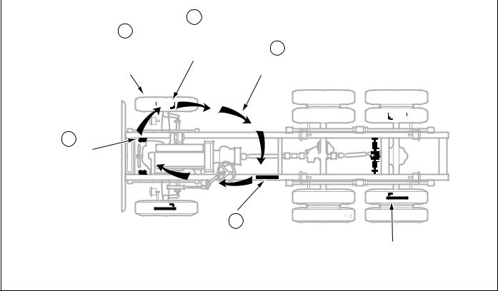
FIGURE 2 - Overview of ABS Operation
2
ABS Component Function
The ABS system operates as follows (see Figure 2).
1.Speed sensors on each wheel monitor wheel rotation.
2.Each speed sensor communicates wheel rotation pulses to the central Electronic Control Unit (ECU).
3.The ECU receives speed sensor input, interprets the signal pulses, and calculates speed and acceleration rates for the wheels and the vehicle.
4.Based on speed sensor input with the brakes applied, the ECU detects impending wheel lock and operates the ABS modulator valves as required for proper control. The modulator valves can be operated in either a release or a hold mode to regulate air pressure in the brake chambers.
5.Braking force is applied at a level which minimizes stopping distance while maintaining as much lateral stability as possible.
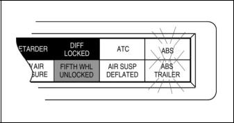
FIGURE 3 - ABS Indicator Lamps
ABS Indicator Lamp
This lamp is the primary indicator of the ABS status.
•The ABS lamp illuminates steadily for a two second bulb-check whenever the switched ignition is ON. The ABS lamp turns OFF after the bulb-check if there are no ABS malfunctions present.
•The ABS lamp flashes on and off continuously when the off-highway mode is selected. (Special option for military and off-highway vehicles.)
•If the Indicator Lamp remains ON, after the bulb-check, there is an ABS diagnostic trouble code that requires service.
NOTE: In the case of a speed sensor failure which has been corrected, the indicator lamp will remain on until sensor output has been verified by the control unit. In this case it is necessary to move the vehicle above 5 mph before the indicator lamp will turn off.
ABS Trailer Indicator Lamp
Tractor/Towing vehicles manufactured on or after March 1, 2001 are equipped with a cab mounted “ABS Trailer” indicator lamp.
When an ABS equipped trailer with Power Line Carrier (PLC) communications capability is connected to the tractor, the ABS Trailer indicator lamp will illuminate for a two second bulb check after the ignition is switched on. The ABS lamp turns OFF after the bulb-check if there are no ABS malfunctions present on the trailer ABS.
If the trailer is NOT equipped with ABS or ABS with PLC capability, the ABS trailer indicator lamp in the cab will not illuminate.
3
Automatic Traction Control (ATC) System
The ATC system is available on all Standard ABS ECU’s. ATC is not available on Basic ECU’s. It helps improve traction on slippery or unstable driving surfaces by preventing excessive wheel spin. ATC also enhances vehicle stability by prevention of power spin-out.
ATC requires:
1.ATC valve - Either a stand alone valve or a Rear Axle Valve Assembly with integral ATC solenoid may be used.
2.SAE J1922 or J1939 engine interface (the ABS ECU serial data interface must match the engine controller interface).
3.Brake Light Switch input.
4.ATC Indicator Lamp.
The Electronic Control Unit (ECU) must be configured for ATC operation either by using the diagnostic switch, an MPSI ProLink® hand-held tester or Eaton’s ServiceRanger PC software.
ATC Operation
During periods of wheel slip, the Electronic Control Unit enters an Automatic Traction Control mode. There are various modes of Automatic Traction Control.
System operation:
•At speeds above 25 mph, the engine is throttled back via the SAE J1922 or SAE J1939 data link to control spin out.
•At speeds below 25 mph, both engine control and differential brake control are activated as required to control wheel slip. Once triggered, differential braking mode remains active regardless of vehicle speed.
•An optional mud and snow switch allows greater wheel spin (more torque) when activated. It is intended for adverse conditions, usually off-highway. Except for special cases, the switch is programmed for momentary operation. ATC reverts to normal operation when the switch is cycled a second time and whenever the system goes through a power-up cycle.
Component Function
When brake control is utilized, the ATC valve is activated, diverting supply tank air to the Modulator Valves on the drive axle(s). The Electronic Control Unit then activates the appropriate solenoids in order to apply a brake force to the spinning wheel. The Automatic Traction Control System cannot increase traction to a particular wheel; it can only utilize the available traction.
Thermal (Brake Heat) Protection
To prevent excessive brake and drum temperature resulting from brake activity, ATC incorporates a brake temperature estimation algorithm to determine when differential braking mode should be suspended. The differential braking function is re-enabled after a cool-down period.
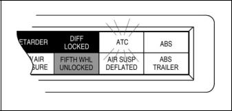
ATC Indicator Lamp
The ATC indicator lamp operates when a vehicle is equipped with the optional Automatic Traction System.
•Gen 4™ ABS – Lights at key-ON and remains lit with ATC inactive until the driver presses the brake pedal.
•Gen 5™ ABS – Lights at key-ON and turns off after a 2 second lamp check. ATC is active after the lamp check.
•Flashes rapidly to indicate that ATC is active.
•Flashes slowly when the “mud-and-snow” mode is selected and then flashes more rapidly when the automatic traction control system operates.
•Remains ON if an engine data link failure occurs.
NOTE: Some non-ATC equipped vehicles have an ATC lamp that is labeled as a spin light. It indicates when a low traction condition has been encountered. No control action is taken.
FIGURE 4 - ATC Indicator Lamp
4
Component Overview
Bendix ABS components include:
•Electronic Control Unit (ECU): The ECU monitors and controls the ABS. It also diagnoses ABS malfunctions and stores specific diagnostic trouble codes.
•Pressure Modulator Valve (PMV): This component regulates brake chamber air pressure. It houses the hold and release solenoids. A modulator valve is located near each brake chamber or pair of brake chambers that make up an ABS controlled wheel site.
•Rear Axle Valve Assembly: An assembly made up of two pressure modulator valves and a relay valve.
•Wheel End Speed Sensor: Single point variable reluctance (magnetic) sensor that generates an alternating voltage signal in response to the movement of teeth on a tone wheel.
•ABS Lamp (Yellow): This indicator lamp, located on the driver instrument panel, warns the driver of ABS malfunctions. It is also capable of blinking diagnostic fault codes when the ECU is in the self-diagnostic mode.
•In-Cab ABS Trailer Lamp: This indicator lamp, located on the driver instrument panel, warns the driver of trailer ABS malfunctions. It is not capable of blinking diagnostic trouble codes.
•ATC Valve: The traction control valve applies full system pressure to the relay valve during traction control operation to provide differential (side to side) braking at controlled drive axles.
•ATC Lamp: This indicator lamp, located on the driver instrument panel, lights to indicate loss of traction which is being managed by the Automatic Traction Control System.
•Relay/Breaker Panel: The OEM provides two circuit breakers and either one or two relays as part of the ABS. One relay is used for indicator lamp control. A second (optional) relay may be used to control a retarder and/or lockup torque converter.
•Diagnostic Port Connector: The diagnostic port connector is an industry standard connector that is used to connect to the J1587 diagnostic link. This connector also provides power and ground for diagnostic test equipment.
5

FIGURE 5 - ABS Components
6
Electronic Control Units (ECUs)
Identification
Frame mount ECUs are environmentally packaged versions of the related Gen 4™ & Gen 5™ ABS cab-mounted units (Standard, Basic). The circuitry and software is the same. Gen 5™ ABS units incorporate power line carrier (PLC) hardware. ECUs are available in 4 and 6-channel versions with either J1922 or J1939 data links. There is also a 24volt version. Further service information is available on www.bendix.com.
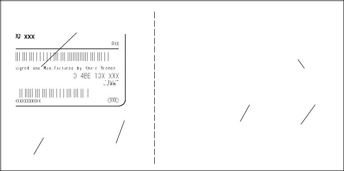
Bendix Part Number
Bendix Part Number
Serial Number |
Date Code |
|
Date Code
Frame Mount
Serial Number |
Cab Mount |
FIGURE 6 - Electronic Control Unit Identification Tags
7
|
|
Gen 4™ & Gen 5™ ABS - Basic Cab Mount |
|
|
|
|
|
|
|
|
|
|
|
|
|
|
|
|
|
H ny |
|
|
H |
|
|
|
|
|
C |
a |
||
|
|
|
|
|
S |
|
erm |
|||
|
X C |
ermany |
|
|
|
|
O |
ein |
G |
|
|
XX S |
|
|
|
300XXXyB |
|
|
|||
|
00 O inG |
|
|
|
redb |
ad |
|
|
||
|
3 byB |
|
|
|
|
ctu |
M |
|
|
|
|
Made |
|
|
|
ufa |
|
|
|
|
|
|
|
|
|
an |
36 |
|
|
|
|
|
Manufactured036 |
|
|
dM |
0 |
|
|
|
862 |
||
|
ed |
an |
04 |
|
|
|
||||
|
|
1 |
|
|
|
|
||||
nedand |
104 |
862 |
sign |
6 |
|
|
|
|
|
|
De 0 |
48 |
|
|
|
313 |
|
||||
Desig 486 |
|
|
|
|
|
|
|
|
||
0 |
|
|
|
|
|
|
8O |
|
|
|
|
FOEO798O313 |
|
|
|
|
79 |
|
|
|
|
|
|
|
|
|
EO |
|
|
|
|
|
|
|
|
|
|
FO |
|
|
|
|
|
|
|
|
|
|
M |
|
|
|
|
|
|
|
|
|
|
|
|
|
|
|
|
|
M |
|
|
|
|
|
|
|
|
|
Gen 5™ ABS – Standard Cab Mount |
Gen 4™ ABS – Standard Cab Mount |
|||||||||
|
|
|
|
|
Sliding Lock |
|||||
|
|
|
|
|
|
ECU Cover |
||||
|
|
Blank |
|
|
|
|
|
|
|
|
|
|
Connector |
|
|
|
|
|
|
|
|
|
|
|
ECU Connector |
|
|
|
|
|
|
|
|
|
|
(1 of 4) |
|
|
|
|
|
|
|
Gen 5™ ABS (PLC - Basic Frame Mount) |
Gen 4™ & Gen 5™ ABS – Standard Frame Mount |
|||||||||
FIGURE 7 - Available Bendix ABS Electronic Control Units
8
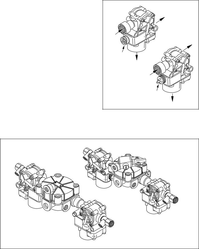
ABS Valves
The ABS modulator valve controls air pressure to individual brake assemblies. Depending on the particular ABS configuration, a system may utilize three, four or six modulator valves. See Figure 8.
Each modulator valve contains two air control solenoids, which act as pilots to the hold and release diaphragms. The hold solenoid blocks inlet air to brake chambers; the release solenoid removes pressure from the brake. The 3-pin threaded connector has pins for the hold and release solenoid and a third, common terminal.
Rear Axle Valve Assemblies
Rear Axle Valve Assemblies are available for some applications depending on OEM preferences. They are combinations of two modulator valves and a relay valve. The assemblies are available in 4.0 and 5.5 PSIG versions, with or without an integral ATC solenoid.
|
1/2 NPT |
|
Delivery Port |
1/2 NPT |
1/2 NPT |
Inlet Port |
Delivery Port |
Twist-Lock |
|
Connector |
Exhaust Port |
|
1/2 NPT |
|
Inlet Port |
|
Threaded |
|
Connector |
|
Exhaust Port |
FIGURE 8 - Modulator Valve
ATC Version |
Standard Version |
FIGURE 9 - Rear Axle Valve Assemblies, 4-Port ABS and ABS/ATC Versions Shown
9
 Vents
Vents 
Solenoid
Hold
Diaphragm
Inlet


 Outlet
 Release
Diaphragm
Exhaust
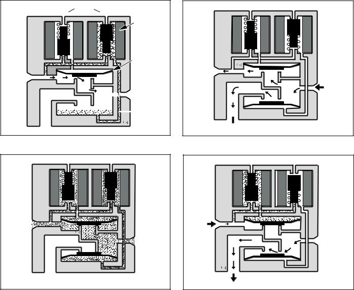
FIGURE 10 - Normal Apply and ABS/ATC Apply
Inlet
Outlet
Exhaust
FIGURE 12 - ABS/ATC Hold
Inlet
Zero 
Pressure
Outlet
 Exhaust
FIGURE 11 - Normal Release
Inlet
 Outlet
Exhaust
FIGURE 13 - ABS/ATC Release
Modulator Valve Operation Modes
1.Apply–Air flows straight through valve. Hold diaphragm is vented to allow air flow. Inlet pressure feeds behind release diaphragm to block the exhaust port. No solenoids are activated.
2.Normal Release–With quick release function, hold diaphragm is vented and there is no pressure at the inlet port. Air is allowed to flow from outlet to inlet. Since release diaphragm is not pressurized, air also flows out the exhaust port. No solenoids are activated.
3.ABS/ATC Hold–The hold solenoid is activated. Both diaphragms are pressurized. No air flows through the valve.
4.ABS/ATC Release–Both solenoids are activated. The hold diaphragm is pressurized, blocking the inlet air. The release diaphragm is vented, allowing air to flow from the outlet port back through the exhaust port.
10
Optional Front Axle Modules
An optional front axle module is available. It is an assembly of two modulator valves and a quick release valve. Three crack pressure settings are available:
• |
0-1 PSIG |
• |
3-4 PSIG |
• |
6-8 PSIG. |
FIGURE 14 - Front Axle Module
Tone
Ring
Wheel End
Sensor
Standard
Wheel End Speed Sensor
Drive and Steer Axles
Right angle version shown
Straight version also available
FIGURE 15 - Sensor Assembly
Speed Sensors
Each wheel of an axle under direct ABS control is monitored by a speed sensor. Speed sensors for drive axles and steer axles may be different styles and installed in different locations.
Wheel End Sensors
For most applications, Bendix ABS uses standard wheel end sensors (see figure 15). The front sensor is accessible on the inboard side of the steering knuckle. The rear drive axle sensor is accessible by removing the wheel and drum assembly.
Wheel-end sensors are conventional, single point, variable reluctance sensors. These are often referred to as "magnetic sensors" or "magnetic pickups." These sensors consist of a rod or pole piece surrounded by a coil of wire. A magnet is closely coupled to the pole piece and circulates a magnetic field through the coil. As the teeth of the tone ring rotate past the pole piece, the resistance (reluctance) to the magnetic field varies. The variable reluctance causes variations in the magnetic field which in turn induce a varying voltage in the coils which are wound around the pole piece.
Some general characteristics of variable reluctance, magnetic sensors are:
• The output voltage decreases as the air gap increases.
•The output voltage increases with the speed of the teeth past the pole piece.
•The output voltage waveform is independent of the direction of wheel rotation.
Wheel-End Sensors are protected with stainless steel metal sheaths. They are designed to fit within beryllium-copper friction sleeves which give them a self-adjustment feature.
11
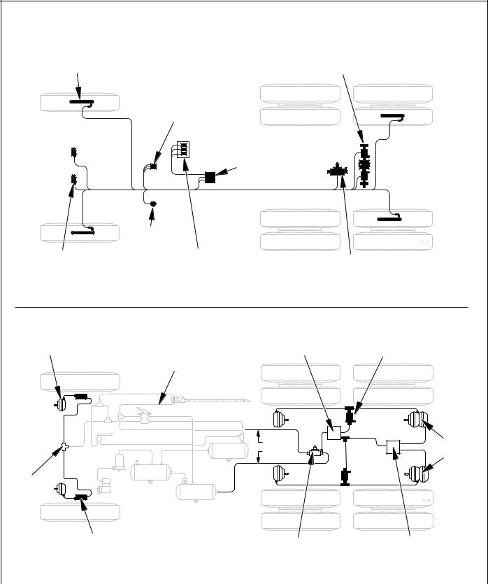
Speed Sensor
Front Axle
Pressure
Modulator Valve
Electrical Layout
Rear Axle
Valve Assembly
Indicator Lamps
ABS Tractor Indicator Lamp (IL)
ABS Trailer IL (after 3/1/01) ATC Lamp (when ATC equipped)
Electronic Control
Unit (ECU)
Cab Mount or
Frame Mount
Diagnostic |
|
|
Connector |
|
|
Diagnostic Switch |
Traction Control Valve |
|
ABS Off Road Switch (optional) |
||
Stand Alone or Integral with |
||
ATC Mud & Snow Switch (optional) |
||
Rear Axle Valve Assembly |
||
|
Pneumatic Layout
Brake
Chamber |
Relay Valve |
Pressure Modulator Valve |
|
Treadle |
|
Control |
Brake |
Supply |
Chambers |
Quick
Release
Valve
Steer Axle |
ATC Valve |
Anti-Compounding |
|
Modulator Valve |
|||
Relay / Quick |
|||
|
|||
|
|
||
|
|
Release Valve |
|
|
|
|
|
FIGURE 16 - Typical Electrical and Pneumatic Layouts |
|
|
12
DIAGNOSTICS
An important feature of Bendix ABS is the system diagnostic capability. This section describes how to retrieve configuration information and error codes to troubleshoot ABS system diagnostic trouble codes. There are three ways to retrieve and display ABS configuration information and trouble codes:
•ServiceRanger PC software: Displays configuration information and diagnostic trouble codes on the PC monitor. Refer to the ServiceRanger PC software information later in this section.
•ProLink hand-held tester: Displays configuration information and diagnostic trouble codes on the handheld tester display. Refer to the hand-held tester information later in this section.
•Diagnostic switch: Flashes configuration code and diagnostic trouble codes on the ABS indicator lamp. Refer to page 18 for operation of the diagnostic switch.
WARNING! PLEASE READ AND FOLLOW THESE INSTRUCTIONS TO AVOID PERSONAL INJURY OR DEATH:
When working on or around a vehicle, the following general precautions should be observed at all times.
1.Park the vehicle on a level surface, apply the parking brakes, and always block the wheels. Always wear safety glasses.
2.Stop the engine and remove ignition key when working under or around the vehicle. When working in the engine compartment, the engine should be shut off and the ignition key should be removed. Where circumstances require that the engine be in operation, EXTREME CAUTION should be used to prevent personal injury resulting from contact with moving, rotating, leaking, heated or electrically charged components.
3.Do not attempt to install, remove, disassemble or assemble a component until you have read and thoroughly understand the recommended procedures. Use only the proper tools and observe all precautions pertaining to use of those tools.
4.If the work is being performed on the vehicle’s air brake system, or any auxiliary pressurized air systems, make certain to drain the air pressure from all reservoirs before beginning ANY work on the vehicle. If the vehicle is equipped with an AD-IS™ air dryer system or a dryer reservoir module, be sure to drain the purge reservoir.
5.Following the vehicle manufacturer’s recommended procedures, deactivate the electrical system in a manner that safely removes all electrical power from the vehicle.
6.Never exceed manufacturer’s recommended pressures.
7.Never connect or disconnect a hose or line containing pressure; it may whip. Never remove a component or plug unless you are certain all system pressure has been depleted.
8.Use only genuine Bendix® replacement parts, components and kits. Replacement hardware, tubing, hose, fittings, etc. must be of equivalent size, type and strength as original equipment and be designed specifically for such applications and systems.
9.Components with stripped threads or damaged parts should be replaced rather than repaired. Do not attempt repairs requiring machining or welding unless specifically stated and approved by the vehicle and component manufacturer.
10.Prior to returning the vehicle to service, make certain all components and systems are restored to their proper operating condition.
11.For vehicles with Antilock Traction Control (ATC), the ATC function must be disabled (ATC indicator lamp should be ON) prior to performing any vehicle maintenance where one or more wheels on a drive axle are lifted off the ground and moving.
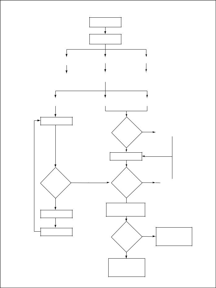
Troubleshooting Procedures
Figure 17 shows an organized approach to troubleshooting ABS trouble codes. Follow the steps listed below to locate and correct ABS component and wiring problems.
1.Check that the ABS ECU configuration corresponds to the ABS components installed on the vehicle. Reconfigure the ECU if the configuration does not match the installed ABS components.
2.Access active diagnostic trouble code(s). Inactive (historical) diagnostic trouble codes are also reported and may provide additional information to aid in troubleshooting.
3.Look up the code description, the possible causes and the repair procedures provided in this section.
4.Perform the recommended repair procedures.
5.After the repairs are completed, clear all codes and check for any additional codes.
13
Cycle ignition key
OFF to ON
Observe ABS indicator lamp operation
|
Lamp turns OFF after |
|
Lamp stays ON |
|
|
Lamp never ON |
|
||
|
2 second lamp check |
|
|
|
|
|
|
|
|
|
|
|
|
|
|
||||
|
|
|
|
|
|
|
|
|
|
|
|
|
|
|
|
|
|
|
|
|
ABS system not reporting |
|
Select Eaton ABS diagnostic tool |
|
|
Check for power to ABS ECU. |
|
||
|
|
|
Check indicator lamp and wiring |
|
|||||
|
Codes–perform traditional |
|
|
|
|
|
|||
|
|
|
|
|
|
|
|
||
|
foundation brake |
|
|
|
|
|
|
|
|
|
|
|
|
|
|
|
|
||
|
troubleshooting and repair |
|
|
|
|
|
|
|
|
|
|
|
|
|
|
|
|
|
|
|
|
|
|
|
|
|
|
||
Activate blink codes |
|
|
Use Service Ranger |
|
|
|
Use MPSI |
|
|
with diagnostic button |
|
diagnostic software |
|
|
|
ProLink tool |
|
||
|
|
|
|
|
|
|
|
|
|
Check ECU configuration
Does tester |
|
|
communicate with |
|
Check J1587 data link wiring |
|
|
|
ECU? |
NO |
|
|
YES
Check ECU configuration
Indicator lamp blinking when activated
with diagnostic YES button?
NO
Check power circuit for ECU
Reconfigure ECU
Does configuration |
|
|
information agree |
|
Reconfigure ECU |
with available |
NO |
|
hardware? |
|
|
|
|
YES 
Read trouble codes and descriptions
Take corrective action
Clear active and inactive trouble codes
Is this a trailer
ECU? YES
NO
Recheck trouble codes after clearing. If indicator lamp remains lit
and 17-12 trouble code is set, drive vehicle to clear and turn off indicator lamp.
Recheck trouble codes after clearing. If indicator lamp remains lit and no trouble codes are set,
drive vehicle to turn off indicator lamp.
FIGURE 17 - Antilock Brake System Troubleshooting Chart
14
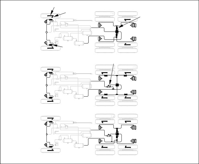
SYSTEM CONFIGURATIONS
Available Configurations
A wide variety of system configurations are available (refer to Figure 17). It is important to be able to read system configurations and to be able to properly reconfigure a system when necessary.
When to Configure
ECUs are factory configured for the most common requirements. Basic systems are setup for 4s-4m operation with retarder control via retarder relay. Standard systems are setup for 6s-4m operation with retarder control via engine data link. For applications other than these factory configurations (for example use of a retarder control relay, 4s-3m operation, 6s-6m operation or traction control), it is necessary to perform a configuration or “setup” process. This process sets up the ECU for the components that are installed so that proper control and fault tolerance will be
implemented. The diagnostic switch, MPSI Pro-Link® tool or ServiceRanger PC software may be used to configure to a higher level (add components or functionality). If it is desired to move the configuration downward (fewer components than standard), the ProLink tool or ServiceRanger PC software must be used.
How to Configure
Use the “SYSTEM SETUP” menu with the MPSI ProLink® tool, the diagnostic switch (refer to page 25 for procedure) or ServiceRanger PC software. Use of the “SETUP” function will also clear inactive trouble codes from the system. However it is recommended that the “CLEAR TROUBLE CODES” function be used for clearing inactive codes.
Verification
It is important to verify that the intended configuration has been obtained. Refer to Figure 20 (page 17) for proper interpretation of configuration blink codes.
Tone Ring |
|
Wheel Speed Sensor |
Rear Axle |
(WSS) |
Valve Assembly |
Pressure |
|
|
Modulator |
|
|
Valve |
|
|
(PMV) |
4S - 4M |
ATC |
|
Valve |
|
|
|
6S - 6M w/ATC
6S - 4M w/ATC
FIGURE 18 - Typical ABS Configurations
15
 Loading...