

Bang Olufsen BeoSound 4 Service Manual

BeoSound 4
Type 2851, 2852, 2853, 2854, 2855, 2857, 2858, 2859, 2860
Service Manual
English
German, French, Italian, Spanish, Danish, Dutch and Japanese
versions are available in the Retail System
This Service Manual must be returned
with the defective parts/back-up suitcase !

CONTENTS
Survey of modules ........................................................................................ 1.1
How to service .............................................................................................. 1.2
PIN-code ....................................................................................................... 1.3
Warnings ...................................................................................................... 1.5
Final check after repair .................................................................................. 1.6
Fault flow chart ............................................................................................. 2.1
Placement of measuring points ..................................................................... 2.2
Placement of magnet .................................................................................. 2.11
Service mode ................................................................................................ 3.1
Service tips .................................................................................................... 4.1
Repair tips ..................................................................................................... 4.2
Replacement of modules ............................................................................... 5.1
Specification guidelines for service use .......................................................... 6.1
Wiring diagram ............................................................................................. 7.1
Available parts .............................................................................................. 8.1
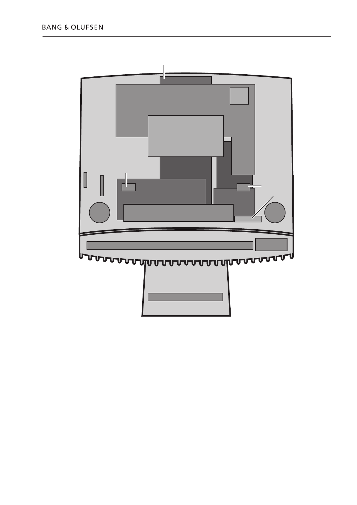
Survey of modules
37
2
10
12
8
96
61
85
5 5
9
3
4
4
7
11
1
Keyboard
6
Survey of modules 1.1
PCB1 .......................... Socket
PCB2 .......................... Master
PCB3 .......................... Magic
PCB4 .......................... Light
PCB5 .......................... Turn wheel
PCB6 .......................... Main microprocessor
PCB7 .......................... Codec
PCB8 .......................... Tacho
PCB9 .......................... Headphone
PCB10 ........................ Display
PCB11 ........................ SD/MMC card reader
PCB12 ........................ Switch
37Module ................... DAB
PCB61 ........................ SMPS
PCB85 ........................ FM tuner EU/JP
96Module ................... CD unit

1.2 How to service
How to service
Converting mains supply voltage
Front line service
The unit has separate type nos. for each market, due to country approvals.
The mains voltage is determined by the type nos. of the unit, there are only two
internal mains voltage settings (a jumper) on the SMPS, 100/120V and
230/240V AC (P108, when mounted = 100/120V).
The BeoSound 4 unit has been developed for simple module exchange to follow
the on-site service strategy. Module exchange is possible onsite, in the shop or in
the service workshop whatever is most convenient in each case. For on-site service
a back-up suitcase must be used. Module exchange is the recommended way to
perform service, due to the fact that most of the modules are multi-layer based,
and most of the circuits are on a single main PCB. An electrical fault symptom can
be removed during one visit to the customer’s home, if you bring a BeoSound 4
back-up suitcase with you. Is it a mechanical symptom, the particular part must be
brought with you separately.
Service documentation
Service documentation for BeoSound 4 will be a Service manual with part no. for
the back-up suitcase, electrical and mechanical parts, user’s guides etc.

PIN-code
PIN-code active prior to service
Service code
PIN-code 1.3
The product has a 4 digit PIN-code, of the user´s own choice, which must be entered
if the product has been disconnected from the mains for 15-30 min.
If the PIN-code is activated, and the product has been without mains for 15-30 min.,
the user will be asked to enter the 4 digit PIN-code when the product is switched on.
Before the product is handed in to service it is a good idea to ask the customer to
deactivate the PIN-code.
The PIN-code is activated when the product is shipped from Bang & Olufsen.
Refer to the user guide for further information.
If the PIN-code is not deactivated prior to service you must use the Service code to
unlock the product.
The service code
-
unlocks the product, but does not affect the pin-code setting
- gives you 12 hours service time
Entering the Service code
When the product asks for PIN-CODE press and hold
1.
2. The Master code menu appears.
3. Enter the Service code: 1 1 1 1 1.
Important notice concerning Service time
The service time is active as long as the product is connected to the mains, including
Standby.
To obtain maximum service time:
Only connect the product to the mains while you are performing actual service on
the product.
When the service time is expired, the product can only be unlocked by entering
the PIN-code or the Master code.
Registration of the modules
The modules will be registered to the product in the following situations:
-
the product has been connected to the mains for more than 12 hours, including
Standby time.
the PIN-code is activated or deactivated.
-
PIN-code deactivated by customer prior to service
With the PIN-code deactivated prior to service you must be aware of the modules
will be registered to the product in the following situations:
-
the product has been connected to the mains for more than 12 hours, including
Standby time.
the PIN-code is activated or deactivated.
The registration of modules in the product can only be changed at Bang & Olufsen.
l for 3 seconds.

1.4 PIN-code
Activate the PIN-code
Enter the PIN-code
If the PIN-code has been forgotten
Select the SETUP menu.
Press
l twice and then STOP to bring up the PINCODE SETUP menu.
Enter the 4 digit Pin-code. Re-enter the code to confirm it and press GO.
If you want to change or delete the PIN-code, enter the correct PIN-code and press GO.
It is now possible to change the PIN-code or delete the PIN-code.
If the PIN-code is activated and the product is disconnected from the mains for
more than15-30 minutes, a PINCODE menu appears as soon as the product is
switched on.
Enter the PIN-code, and the product starts again.
If the PIN-code has been forgotten the only way to unlock the product again is by
entering a 5 digit Master-code.
The Master-code is ordered by sending a request via the Retail System.
When the product prompts for a PIN-code, press and hold
l down to bring up the
MASTERCODE menu.
Enter the Master-code and press GO. This will deactivate the PIN-code and
reactivate the product.
Product locked by PIN-code
The product is locked by PIN-code when:
-
The PIN-code is activated and the mains is disconnected for more than 15- 30
minutes.
The product is unlocked when the PIN-code is entered.
The PIN-code counter is set to 5 attempts within 3 hours.
When a wrong PIN-code has been entered 5 times within 3 hours, the product
cannot receive any commands for a period of 3 hours.
After this period the PIN-code counter is reset.
The product must be in standby mode to activate the timer.
Warnings
STATIC ELECTRICITY
MAY DESTROY THE
PRODUCT
ESD
Laser exposure
Warnings 1.5
When electrical replacements or disassembly all taking place, use an ESD-mat.
The internal electronics are very sensitive to static electricity.
When mains voltage on BeoSound 4 is required, remove the connection from
BeoSound 4 to the ESD mat.
BeoSound 4 contains a laser system and is classified as a class 1 laser product.
BeoSound 4 must be opened by qualified personal only.
CLASS 1
LASER PRODUCT
General warnings
Cleaning
Wear cotton gloves to avoid fingerprints on the product. The display surface on
the product is very sensitive, so handling should be done with great care to avoid
damage. When transporting BeoSound 4, it is recommended to use the product
cover, part no. 3375490.
Be sure that the plugs in each end are connected correctly.
Clean BeoSound 4 surfaces using DuPont Polishing Cloth, part no. 3624018.
Finally clean the front glass with DuPont Final Tack Cloth. It prevents electrostatic
buildup. Never use alcohol or other solvents to clean any parts of BeoSound 4.

1.6 Final check after repair
Final check after repair
Isolation test
Isolation test at the customer
Each set must be insulation tested after having been dismantled. Make the test
when the set has been reassembled and is ready to be returned to the customer.
Flashovers must not occur during the testing procedure! Make the insulation test
as follows: Short-circuit the two pins of the mains plug and connect them to one
of the terminals of the insulation tester. Connect the other terminal of the insulation
tester to the chassis pin of the aerial socket.
NOTE!
To avoid damaging the set, it is essential that both terminals of the insulation
tester have good contact. Slowly turn the voltage control of the insulation tester
until a voltage of 2.5 kV and max. 5 mA is obtained. Maintain that voltage for one
second, and then slowly turn it down again.
Remove the mains cable from the wall outlet. Place a jumper across the two AC
plug prongs. Use a multi-meter, set for measurements in the ohm-area. Place one
lead from the multi-meter on the AC plug and place the other lead on ground at
the power link plug. The resistance during this measurement must be of 1 mega
ohm or more. Resistance measured below 1 mega ohm indicates an abnormal
situation and corrective action must be taken.
Test of the device
After the insulation test, it is important to do the final test of the device, to make
sure there are no other faults.
1.
Turn on BeoSound 4 and load a CD. Play the CD.
2. Switch to SD play mode.
3. Switch to FM radio and make a tuning.
4. Switch to DAB radio and make a tuning.
5. Use volume up/down.
6. Make sure that both the remote control and the buttons work perfectly.
Before finishing the device, make sure that the option setting is correct.

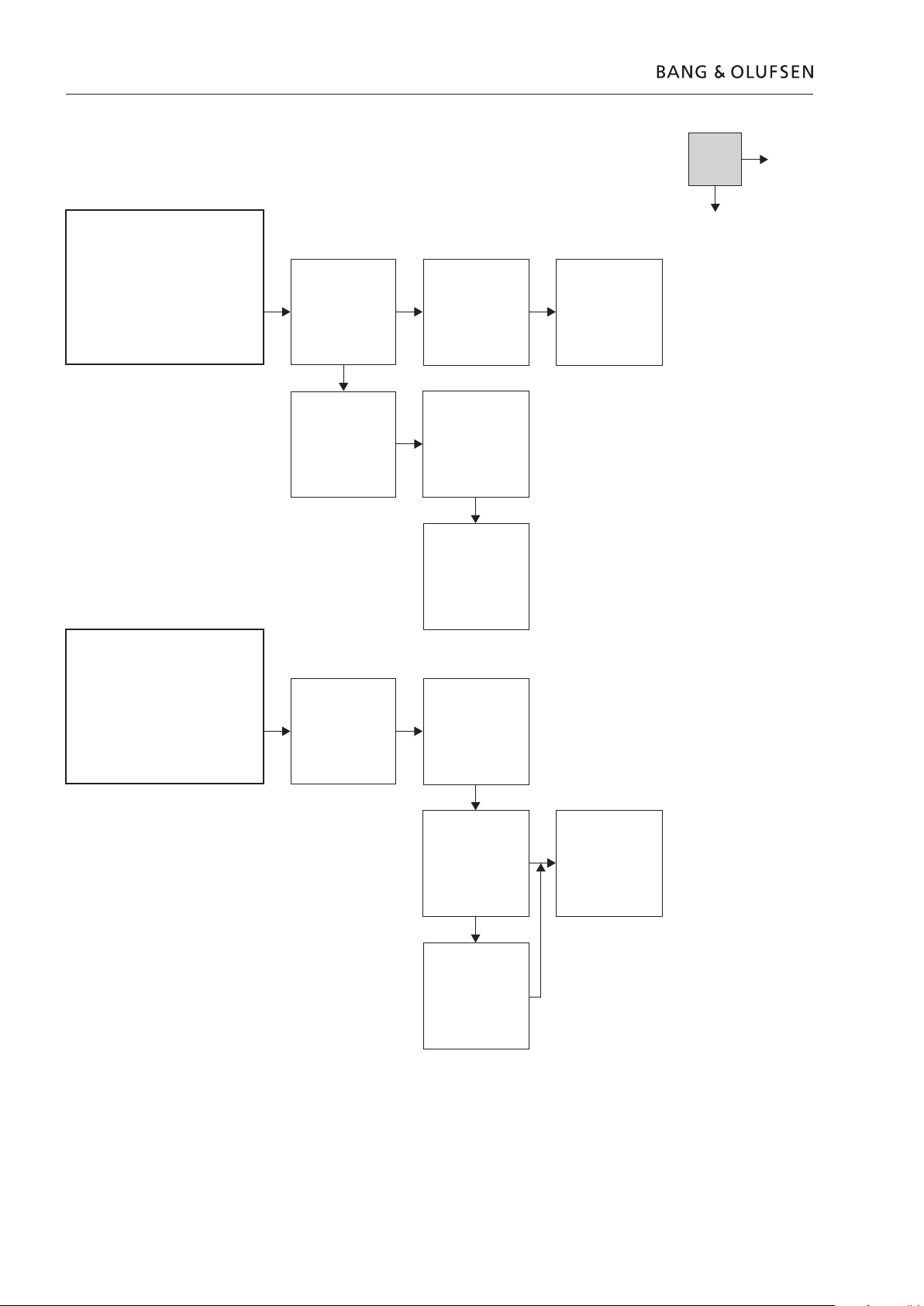
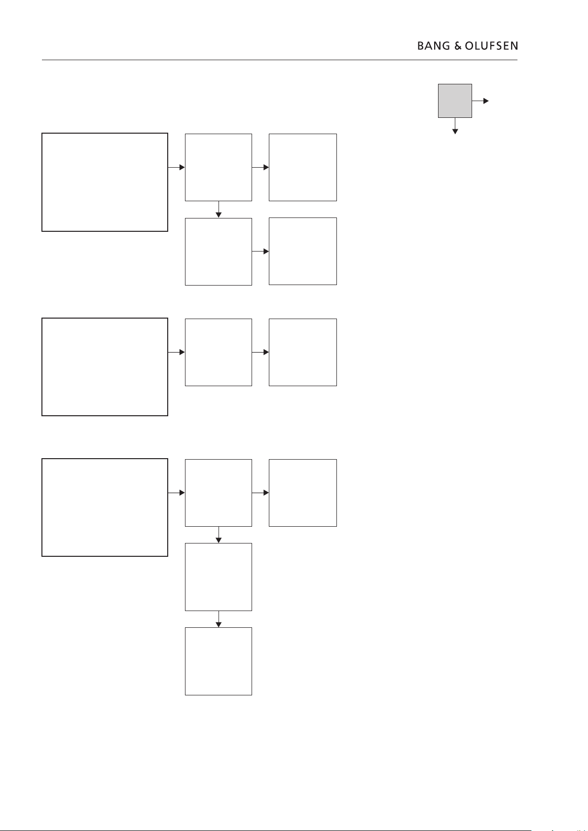
Fault flow chart
Instructions
Fault flow chart 2.1
Instructions before trouble shooting in the fault flow chart:
•
In the following fault flow chart BeoSound 4 is named BS4.
• Never connect or disconnect a socket, when the power is turned on.
Disconnect the mains supply and wait minimum 30 seconds for the electrolytic
capacitors to discharge.
When measuring voltages BS4 must be in CD mode,
•
When fault finding in CD use Bang & Olufsens test CD 3634031 (SBC444A).
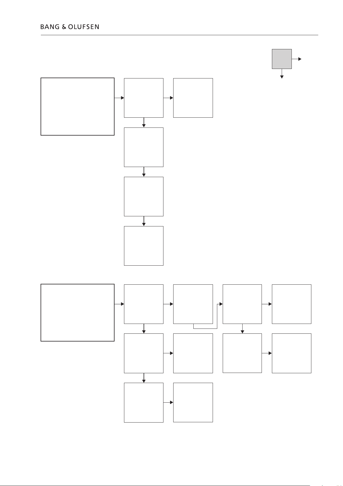
2.2 Fault flow chart
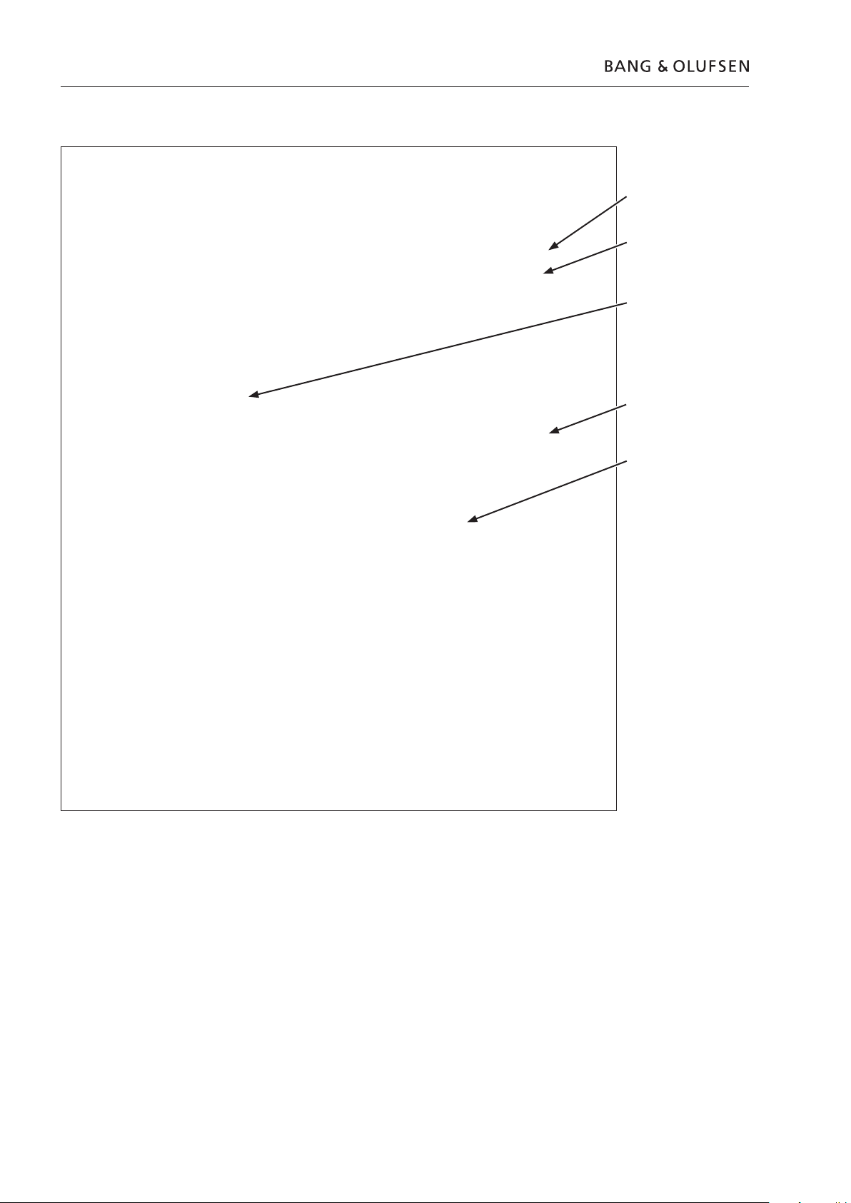
Placement of measuring points
6V - IC1000 pin1
5V_CD - IC1000 pin5
9V_CD
Mains supply - P101
5V_SB
1
2V - IC1 pin8
-12V - IC1 pin4
@uPH8
6V
5V_CD
9V_CD
Mains supply
P
101
Fault flow chart 2.3
@back of display
5V_SB
@Headphone jack
-
12V
+12V
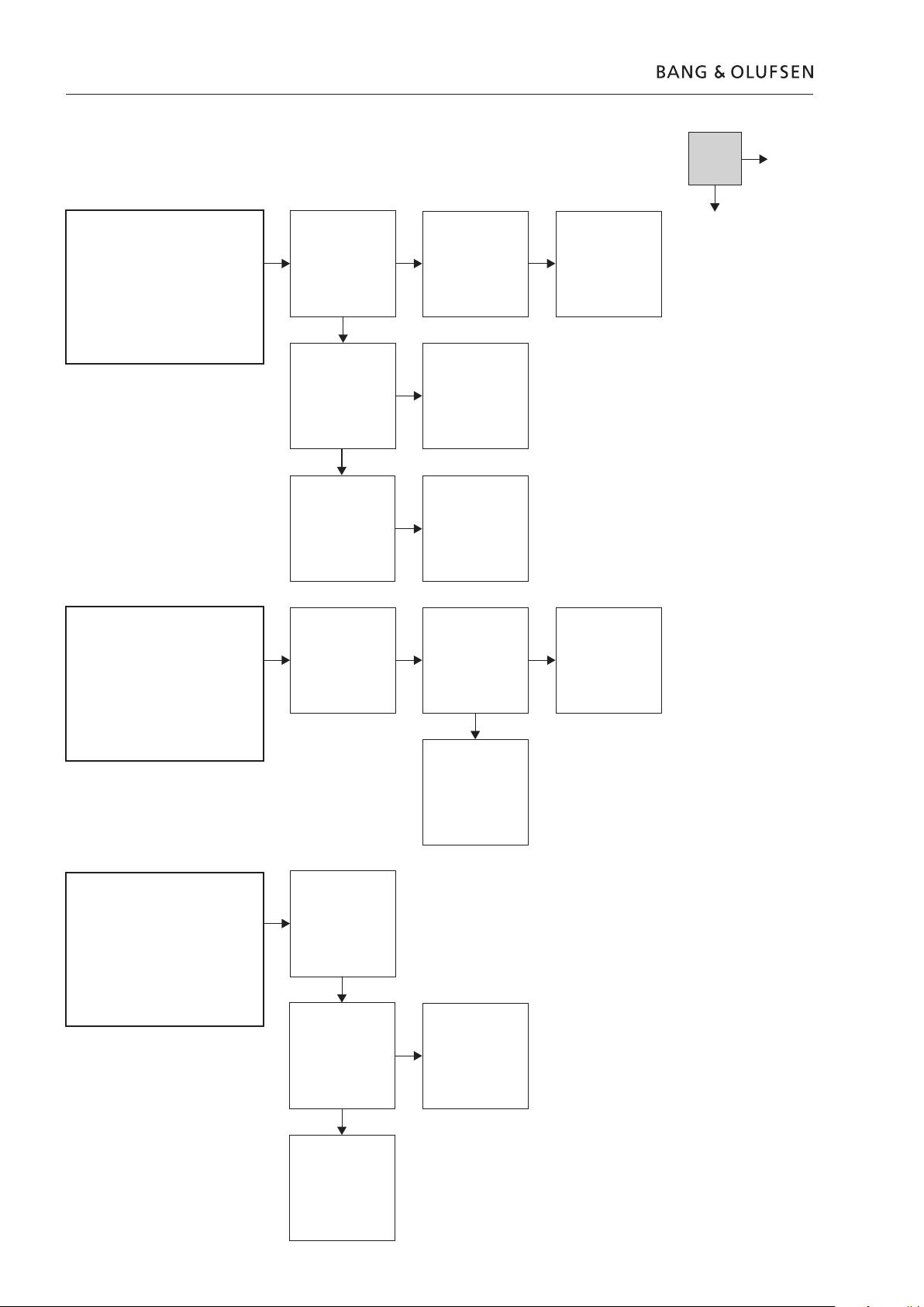
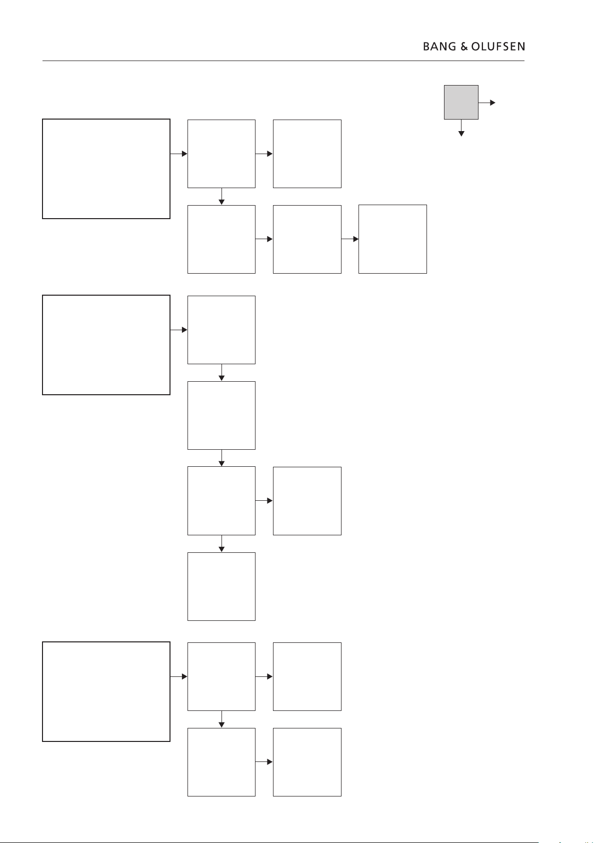
2.4 Fault flow chart
Fault symptom:
- Fault in voltages
Possible causes:
- PCB61, SMPS
- Connections
Measure mains supply
101 OK?
Fuse F
e 12V, -12V,
Measur
6V 5V_SB
OK?
Measure connection
to Socket, PCB
Measure all
connections in BS4
are all right
1
OK?
No
Yes
Re-establish
connection
Fault symptom:
ont glass does not close
- Fr
Possible causes:
- Bright light shining on the product
- PCB3, Magic
Use menu to change
sensitivity of the door
censors
OK?
Change
PCB6
1, SMPS
Lift the front glass a
little
Push “Load”
Front glass opens
BS4 is placed in bright
light?
Move BS4 to another
place
OK?
Measure connections
or replace PCB3,
Magic
Fault symptom:
- No stand-by light
- Unable to use/r
Possible causes:
- PCB61, SMPS
- Fuse F
101
emote BS4
Measure mains supply
Fuse F
101 OK?
Connections from
1 to other
PCB6
boards OK?
Fault flow chart 2.5
No
Yes
Replace defect fuse
Re-create connection
Fault symptom:
- No sound in headphone
Possible causes:
- PCB9, headphone connector
- PCB2, Master
Replace PCB6
Unplug headphone
Sound in speaker?
Sound in headphone?
1, SMPS
Plug another
headphone
Switch to FM
Sound in speaker?
Connection from
PCB2 to PCB9 OK?
Change PCB9,
Headphone
Change PCB2, Master
Re-establish
connection
Change PCB2, Master
2.6 Fault flow chart
No
Yes
Fault symptom:
- Unable to remote with turn wheel
Possible causes:
- Connection not OK
- Defect turn wheel
- PCB3, Magic open defect
Fault symptom:
- Unable to use MasterLink
Possible causes:
rong option setting
- W
- ML cable
- PCB2, Master
Both wheels defect
Connection to PCB5,
PCB3, PCB6 and
keyboard OK?
Keyboard OK?
Check option setting
Refer to user guide
OK?
Connection to PCB5,
PCB3 and keyboard
OK?
Re-establish
connection
Change PCB3, Magic
Check ML cable
e.g. try another cable
Connect to another
product
OK?
Change defect PCB5,
Turn wheel
Change PCB2, Master
Fault symptom:
- No power
- Stand-by led not lit
- Unable to r
Possible causes:
- PCB61, SMPS
emote
Measure connection
Measure mains supply
Change PCB61, SMPS
to PCB6
Fuse F
1, SMPS
101 OK?
Change cable
Re-establish
connection
Change fuse
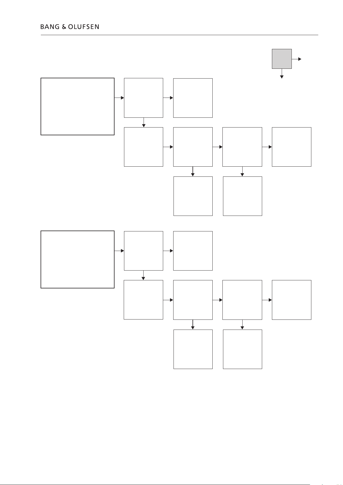
Fault flow chart 2.7
No
Fault symptom:
- Unable to play CD (test CD)
- No disc r
- Playback with SD car
- Cable connection to CD PCB OK
Possible causes:
- Focus pr
- PCB76, CD board
- PCB96, CD unit
Fault symptom:
- Regular dr
playing CD
- CD stops playing/r
- CD search problem
Possible causes:
- Tracking problem
- Dirty lens
- PCB76, CD board
- PCB96, CD unit
otation
d OK
oblem
opouts/mute when
otating
Establish fault
symptom with B&O
Test CD
Fault symptoms
established?
Clean lens with
isopropyl alcohol and
play disk
OK?
Establish fault
symptom with B&O
Test CD
Fault symptoms
established?
Clean lens with
isopropyl alcohol and
play disk
OK?
Establish the fault with
customer’s CD
Check the disk for
visible defects
Report fault and send
the customer CD to
B&O for analyse
Measure supply
voltages to CD
mechanism
CB2, IC100 pin5 - 5V
P
PCB2, IC1003, pin4 - 9V
Measure connections
are correctly connected
Change PCB96, CD
unit
Establish the fault with
customers CD
Check the disk for
visible defects
Report fault and send
the customer CD to
B&O for analyse
Measure supply
voltages to CD
mechanism
P
CB2, IC100 pin5 - 5V
PCB2, IC1003, pin4 - 9V
Measure connections
are correctly connected
Measure supply voltages
to CD mechanism
P
CB2, IC1000, pin1 - 6V
PCB2, IC1003, pin2 - 12V
Change PCB2, Master
Measure supply voltages
to CD mechanism
P
CB2, IC1000, pin1 - 6V
PCB2, IC1003, pin2 - 12V
Yes
Change PCB61, SMPS
Change PCB61, SMPS
Change PCB96, CD
unit
Change PCB2, Master
2.8 Fault flow chart
No
Yes
Fault symptom:
- Fault in display
- Only a few lines are faulty
Possible causes:
- PCB
10, display
- Connections to display
Fault symptom:
- Fault in display
- Nothing in display
- Stand-by led OK
- Able to r
- Able to play CD
Possible causes:
- PCB10, display
- Connections to display
emote
Measure connections
to the display is OK?
Change PCB
Change PCB10,
Display OK?
10,
Display
OK?
Re-establish
connection
Change PCB2, Master
Change PCB2, Master
Fault symptom:
- Unable to play FM
- CD plays OK
Possible causes:
- PCB85, tuner
- PCB6
1, SMPS
Measure voltages
12V
+
Measure connections
to tuner OK
Replace PCB85, tuner
Replace PCB61, SMPS
Fault symptom:
- Unable to play DAB
- CD plays OK
- FM plays OK
Possible causes:
- PCB37, DAB
- PCB61, SMPS
Measure voltages +6V
DAB aerial is mounted
Replace PCB6
Fault flow chart 2.9
No
Yes
1, SMPS
Fault symptom:
- Unable to open fr
Possible causes:
- PCB3, Magic door censor
- PCB61, SMPS
- Motor
ont glass
Measure connections
to DAB OK
Replace PCB3
Lift the glass so the
keyboard is visible
Press the “Load”
The front glass slides
BS4 in service position
Measure connection to
Confirm voltage
7, DAB
button
up?
PCB3, Magic
5V_SB & 6V
Measure connection
to PCB3, Magic
Change PCB6
1, SMPS Change PCB3, Magic
Measure voltages
5V_SB & 6V
Change PCB6
Change PCB2, Master
1, SMPS
Change PCB3, Magic
OK?
Change PCB2, Master
2.10 Fault flow chart
No
Fault symptom:
- The front glass slides to the top
without stopping above the
keyboar
Possible causes:
- PCB8, T
Fault symptom:
- Unable to load CD
- Fr
- Front glass slides down a little and
nothing else happens
Possible causes:
- PCB12, Switch
- PCB2, Master
d
acho
ont glass does not open
Connection to PCB8,
Tacho
OK?
Change PCB8, Tacho
OK?
Check if the magnet
on the door
mechanism is
mounted
e page 2.11
See figur
Measure connection
to PCB8, Tacho &
PCB
12, Switch
Re-establish
connection
Replace PCB2, Master
Yes
Replace motor unit
Fault symptom:
- No sound in loudspeaker and/or
headphone
- Radio/DAB OK
- CD OK
Possible causes:
- PCB2, Master
- PCB
1, Socket
Door mechanism must
be in lower position
Measur
e 3.3V PCB12
P1 pin2
Change
PCB12, Switch
Measure voltages
OK?
Change PCB2, Master Change PCB
Change PCB2, Master
Change PCB6
1, SMPS
1, Socket
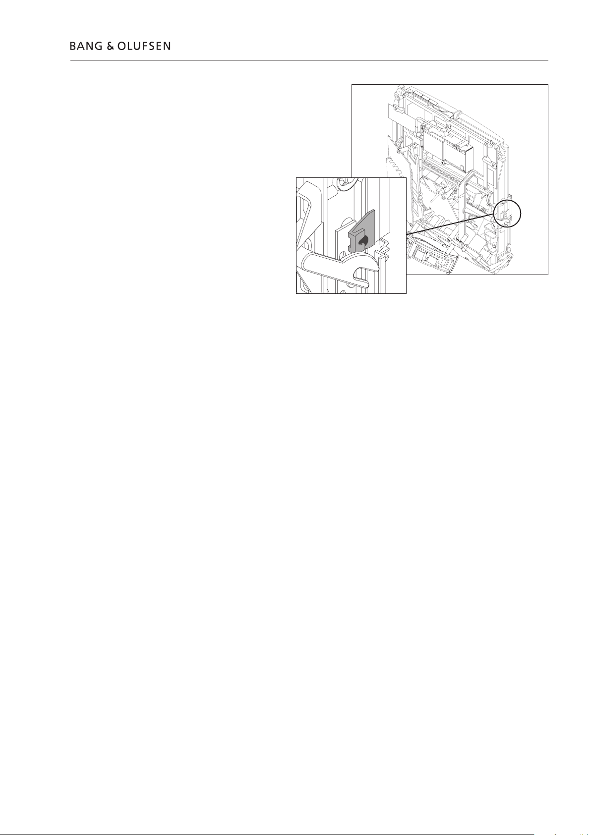
Placement of magnet
Fault flow chart 2.11

2.12

Service Mode 3.1
Not completed
 Loading...