


 Loading...
Cyclades® ACS 6000
Installation/Administration/User Guide

FCC Warning Statement
The Cyclades ACS advanced console server has been tested and found to comply with the limits for Class A digital devices, pursuant to Part 15 of the FCC rules. These limits are designed to provide reasonable protection against harmful interference when the equipment is operated in a commercial environment.
This equipment generates, uses and can radiate radio frequency energy and, if not installed and used in accordance with the Installation and Service Manual, may cause harmful interference to radio communications.
Operation of this equipment in a residential area is likely to cause harmful interference in which case the user is required to correct the problem at his or her own expense.
Notice about FCC Compliance for All Cyclades ACS Advanced Console Server Models
To comply with FCC standards, the Cyclades ACS advanced console server requires the use of a shielded CAT 5 cable for the Ethernet interface. Notice that this cable is not supplied with either of the products and must be provided by the customer.
Canadian DOC Notice
The Cyclades ACS advanced console server does not exceed the Class A limits for radio noise emissions from digital apparatus set out in the Radio Interference Regulations of the Canadian Department of Communications.
L’Cyclades ACS advanced console server n’émete pas de bruits radioélectriques dépassant les limites applicables aux appareils numériques de la classe A prescrites dans le règlement sur le brouillage radioélectrique edicté par le Ministère des Communications du Canada.
Safety and EMC Approvals and Markings
FCC Class A (USA), CE Class A (EU), ICES-003 (Canada), VCCI (Japan), C-Tick (Australia, no internal modem), A-Tick (Australia, with internal modem), UL 60950-1 (USA), cUL (Canada), EN-60950-1 (EU), CB

Cyclades® ACS 6000
Advanced Console Server
Installation/Administration/User
Guide
Avocent, the Avocent logo, The Power of Being There, DSView and Cyclades are registered trademarks of Avocent Corporation or its affiliates in the US and other countries. All other marks are the property of their respective owners.
© 2008 Avocent Corporation. 590-767-501B

Instructions
This symbol is intended to alert the user to the presence of important operating and maintenance (servicing) instructions in the literature accompanying the appliance.
Dangerous Voltage
This symbol is intended to alert the user to the presence of uninsulated dangerous voltage within the product’s enclosure that may be of sufficient magnitude to constitute a risk of electric shock to persons.
Power On
This symbol indicates the principal on/off switch is in the on position.
Power Off
This symbol indicates the principal on/off switch is in the off position.
Protective Grounding Terminal
This symbol indicates a terminal which must be connected to earth ground prior to making any other connections to the equipment.

iii
TABLE OF CONTENTS
List of Figures ................................................................................................................ |
vii |
List of Tables................................................................................................................... |
ix |
Chapter 1: Introduction ................................................................................................... |
1 |
Features and Benefits ........................................................................................................................ |
1 |
Web Manager.............................................................................................................................. |
1 |
Access options............................................................................................................................. |
2 |
IPv4 and IPv6 support ................................................................................................................ |
2 |
Flexible users and groups........................................................................................................... |
3 |
Security ....................................................................................................................................... |
3 |
Authentication............................................................................................................................. |
3 |
VPN based on IPSec with NAT traversal ................................................................................... |
3 |
Packet filtering............................................................................................................................ |
4 |
SNMP.......................................................................................................................................... |
4 |
Data logging, notifications, alarms and data buffering ............................................................. |
4 |
Power management .................................................................................................................... |
4 |
Auto discovery ............................................................................................................................ |
5 |
Configuration Example...................................................................................................................... |
5 |
Chapter 2: Installation ..................................................................................................... |
7 |
Rack Mounting................................................................................................................................... |
7 |
Connecting the Hardware.................................................................................................................. |
8 |
ACS console server connectors .................................................................................................. |
8 |
Device consoles or modems to serial ports ................................................................................ |
9 |
Power devices ........................................................................................................................... |
11 |
Power Configuration ....................................................................................................................... |
12 |
ACS 6000 Remote Console Server Configuration ........................................................................... |
13 |
Making an Ethernet connection................................................................................................ |
14 |
Making a direct connection ...................................................................................................... |
14 |
Accessing an ACS Console Server................................................................................................... |
15 |
Using the Web Manager ........................................................................................................... |
15 |
Using Telnet/SSH...................................................................................................................... |
15 |

iv |
Cyclades ACS 6000 Advanced Console Server Installation/Administration/User Guide |
|
|
Pluggable Devices Installation and Configuration ......................................................................... |
17 |
|
Chapter 3: Web Manager Overview.............................................................................. |
19 |
|
First Time Configuration ................................................................................................................. |
19 |
|
Web Manager Overview for Administrators.................................................................................... |
22 |
|
Web Manager Overview for Regular Users .................................................................................... |
25 |
|
Chapter 4: Using the Web Manager.............................................................................. |
27 |
|
Global Settings................................................................................................................................. |
27 |
|
Sessions..................................................................................................................................... |
27 |
|
Sensors...................................................................................................................................... |
27 |
|
Data buffering........................................................................................................................... |
28 |
|
Network Configuration .................................................................................................................... |
28 |
|
IPv6 options.............................................................................................................................. |
28 |
|
Devices options......................................................................................................................... |
29 |
|
Bonding options........................................................................................................................ |
30 |
|
IPv4 and IPv6 static routes options.......................................................................................... |
30 |
|
DNS options.............................................................................................................................. |
31 |
|
Host options.............................................................................................................................. |
31 |
|
Ports Configuration ......................................................................................................................... |
32 |
|
Physical Ports........................................................................................................................... |
32 |
|
CAS Profile ............................................................................................................................... |
33 |
|
Dial-In Profile .......................................................................................................................... |
36 |
|
Power Profile............................................................................................................................ |
37 |
|
Pluggable Devices ........................................................................................................................... |
38 |
|
Security Configuration..................................................................................................................... |
39 |
|
Authentication.................................................................................................................................. |
41 |
|
Appliance authentication .......................................................................................................... |
42 |
|
Authentication servers .............................................................................................................. |
42 |
|
Users Accounts and User Groups.................................................................................................... |
44 |
|
Users accounts.......................................................................................................................... |
44 |
|
User groups .............................................................................................................................. |
45 |
|
Syslog ............................................................................................................................................... |
50 |
|
Event Notifications........................................................................................................................... |
50 |
|
Event Notifications - Settings ................................................................................................... |
51 |
|
Event Notifications - Events...................................................................................................... |
52 |

Table of Contents |
v |
Firewall Configuration .................................................................................................................... |
52 |
IPSec(VPN) ...................................................................................................................................... |
55 |
SNMP Configuration ....................................................................................................................... |
56 |
Date and Time.................................................................................................................................. |
57 |
Boot Configuration .......................................................................................................................... |
58 |
Online Help...................................................................................................................................... |
59 |
Power Management ......................................................................................................................... |
59 |
Settings ..................................................................................................................................... |
60 |
Management ............................................................................................................................. |
61 |
Outlet Groups ........................................................................................................................... |
61 |
Power configuration ................................................................................................................. |
62 |
Configuring a port for a connected PDU ................................................................................. |
62 |
Monitoring ....................................................................................................................................... |
66 |
Active Sessions................................................................................................................................. |
67 |
Appendices..................................................................................................................... |
69 |
Appendix A: Techical Specifications ............................................................................................... |
69 |
Appendix B: Safety, Regulatory and Compliance Information........................................................ |
71 |
Appendix C: Technical Support....................................................................................................... |
75 |

vi Cyclades ACS 6000 Advanced Console Server Installation/Administration/User Guide

vii
LIST OF FIGURES
Figure 1.1: Typical ACS 6000 Advanced Console Server Configuration ......................................... |
5 |
Figure 2.1: Bracket Connections for Front Mount Configuration.................................................... |
7 |
Figure 2.2: Front of the Console Server with PC Card Slots and LEDs (ACS 6032 Console |
|
Server Shown) .................................................................................................................................. |
8 |
Figure 2.3: Rear of the Console Server (ACS 6032 Console Server Shown) .................................... |
9 |
Figure 2.4: Example: Daisy-chained Cyclades PDUs .................................................................... |
11 |
Figure 2.5: DC Power Connection Terminal Block ........................................................................ |
13 |
Figure 3.1: Administrator Web Manager Screen ............................................................................ |
22 |
Figure 3.2: Web Manager Regular User Screen ............................................................................. |
25 |

viii Cyclades ACS 6000 Advanced Console Server Installation/Administration/User Guide
ix
LIST OF TABLES
Table 1.1: Typical ACS 6000 Advanced Console Server Configuration Descriptions |
..................... 5 |
Table 2.1: Connectors on the Console Server Front ......................................................................... |
8 |
Table 2.2: LEDs on the Console Server Front .................................................................................. |
8 |
Table 2.3: Connectors on the Console Server Rear .......................................................................... |
9 |
Table 2.4: Cyclades Serial Port Pinout ........................................................................................... |
10 |
Table 2.5: Cisco Serial Port Pinout................................................................................................. |
10 |
Table 2.6: DC Power Connection Details ....................................................................................... |
13 |
Table 3.1: Web Manager Screen Areas ........................................................................................... |
22 |
Table 3.2: Web Manager Options for Administrators..................................................................... |
23 |
Table 3.3: Web Manager Regular Users Screen Functional Areas ................................................ |
25 |
Table 3.4: Web Manager Options for Regular Users...................................................................... |
25 |
Table 4.1: CAS Profile Options ....................................................................................................... |
33 |
Table 4.2: Security Profile Services, SSH, and HTTP/HTTPS Definitions ..................................... |
40 |
Table 4.3: Event Notifications - Settings Screen Description ......................................................... |
51 |
Table 4.4: Firewall Configuration - TCP and UDP Options Fields ............................................... |
53 |
Table 4.5: Field and Menu Options for Configuring IPSec(VPN) .................................................. |
55 |
Table 4.6: Monitoring Screens ........................................................................................................ |
66 |
Table A.1: Technical Specifications for the ACS 6000 Console Server Hardware......................... |
69 |

x Cyclades ACS 6000 Advanced Console Server Installation/Administration/User Guide

1
CHAPTER
1 Introduction
The Cyclades ACS 6000 advanced console server is a 1U appliance that serves as a single point for access and administration of connected devices, such as target device consoles, modems and power devices. ACS 6000 console servers support secure remote data center management and out-of-band management of IT assets from any location worldwide.
NOTE: Unless noted, references to the ACS 6000 console server refer to all models in the 60XX series.
ACS 6000 console servers provide secure local (console port) and remote (IP and dial-up) access. The console servers run the Linux® operating system with a persistent file system in Flash memory, and they can be upgraded from either an FTP or DSView® software server.
You can use the Web Manager, the Command Line Interface (CLI utility) or DSView 3 management software (version 3.5.1 and greater) to configure the ACS 6000 console server. Multiple administrators can be logged into the console server at the same time.
Two PC card/slots support modem (V.92 and Wireless GSM/CDMA), Ethernet, fast Ethernet (fiber optic), wireless LAN and storage PC cards (16 bit and 32 bit). One USB port supports modem (V.92 and Wireless GSM/CDMA), storage devices and USB hubs. Two fast Ethernet ports support connections to more than one network or configuration of Ethernet bonding (failover) for redundancy and greater reliability. For dial-in and secure dial-back with Point-to-Point Protocol (PPP), optional internal modems can be factory installed, or you can use external modems or wireless modem CardBus devices.
Features and Benefits
Web Manager
Users and administrators perform most tasks through the Web Manager (accessed with HTTP or HTTPS). The Web Manager runs in any supported browser (such as Netscape®, Internet Explorer®, Firefox® or Mozilla®) on any supported computer that has network access to the console server.
The administrator can use the Web Manager to create user accounts, authorize groups and configure security and ports. An authorized user can access connected devices through the Web

2 Cyclades ACS 6000 Advanced Console Server Installation/Administration/User Guide
Manager to troubleshoot, maintain, cycle power, reboot connected devices and change the user password. For more information on the Web Manager, see Chapters 3 and 4.
Access options
Secure access is available through the following local (analog console port) and remote (digital IP and dial-up) options:
•LAN/WAN IP network connection.
•Dial-up either to a factory-configured internal modem (optional), to a modem connected either to a serial port or the AUX port (which is only possible when an internal modem is not installed), or to a PC phone card (modem, GSM or CDMA) installed in one of the PC card slots or in the USB port.
•Target device connection. If a serial port is connected to the console of a device, an authorized user can make a Telnet, SSH v1 or SSH v2 connection to the device console through the Web Manager. An authorized user can also use a Telnet or SSH client to make a connection directly to the console of a target device. (For Telnet or SSH to be used for target device connections, the Telnet or SSH service must be configured in the security profile that is in effect.)
•ACS 6000 console server console connection. An administrator can log in either from a local terminal or from a computer with a terminal emulation program that is connected to the console port and can use the CLI utility. The CLI utility prompt (--|- cli>) displays at login.
More than one administrator (root or admin or a user in the administrator group) can log into the console server and have an active CLI or Web Manager session. All sessions receive a warning message when the configuration is changed by another administrator or by the system: The appliance configuration has been altered from outside of your session. Upon receipt of this message, each administrator needs to verify that changes made during the session were saved.
NOTE: If cron jobs are run by automated scripts, a root or admin user login can cause the cron jobs to fail.
IPv4 and IPv6 support
The ACS 6000 console server supports dual stack IPv4 and IPv6 protocols. The administrator can use the Web Manager or CLI to configure support for IPv4 addresses only or for both IPv4 and IPv6 addresses. The following list describes the IPv6 support provided in the console server:
•DHCP
•Dial-in sessions (PPP links)
•DSView software integration
•eth0 and eth1 Ethernet interfaces
•Firewall (IP tables)
•Linux kernel
•Remote authentication: Radius, Tacacs+, LDAP and Kerberos servers
•SNMP

Chapter 1: Introduction |
3 |
|
|
•SSH and Telnet access
•Syslog server
NOTE: Remote authentication NIS and IPSec are not supported with IPv6.
Flexible users and groups
An account can be defined for each user on the console server or on an authentication server. The admin and root users have accounts by default, and either can add and configure other user accounts. Access to ports can be optionally restricted, based on authorizations that an administrator can assign to custom user groups. Groups can be authorized to manage power while connected to devices. For more information, see Users Accounts and User Groups on page 44.
Security
Security profiles determine which network services are enabled on the console server. Using the Web Manager or the CLI, you can configure automatic detection of PC cards and USB devices or RPC. You can either allow all users to access enabled ports or allow the configuration of group authorizations to restrict access. You can also select a security profile, which defines which services (FTP, ICMP, IPSec and Telnet) are enabled and SSH and HTTP/HTTPS access. The administrator can select either a preconfigured security profile or create a custom profile. For more information, see Security Configuration on page 39.
Authentication
Authentication can be performed locally, with One Time Passwords (OTP), or on a remote Kerberos, LDAP, NIS, Radius or TACACS+ authentication server. If the ACS 6000 console server is managed by a DSView 3 server, DSView authentication is also supported. The console server also supports remote group authorizations for the LDAP, Radius and TACACS+ authentication methods. Fallback mechanisms are also available.
An administrator can configure authentication using the CLI utility and the Web Manager. Any authentication method that is configured for the console server or the ports is used for authentication of any user who attempts to log in through Telnet, SSH or the Web Manager. For more information, see Authentication on page 41.
VPN based on IPSec with NAT traversal
If IPSec is enabled in the selected security profile, an administrator can use the VPN feature to enable secure connections. IPSec encryption with optional NAT traversal (which is configured by default) creates a secure tunnel for dedicated communications between the console server and other computers that have IPSec installed, such as routers, firewall machines, application servers and end-user machines. ESP and AH authentication protocols, RSA Public Keys and Shared Secret are supported. For more information, see IPSec(VPN) on page 55.

4 Cyclades ACS 6000 Advanced Console Server Installation/Administration/User Guide
Packet filtering
An administrator can configure the device to filter packets like a firewall. Packet filtering is controlled by chains. A chain is a named profile configured with one or more rules that define both a set of characteristics to look for in a packet and what to do with any packet that has the defined characteristics. The console server filter table contains a number of built-in chains that cannot be deleted; all input and output packets and packets to be forwarded are accepted. The policies for how to handle built-in chains can be modified.
To configure packet filtering, an administrator can add a new chain and specify rules for that chain, add new rules to existing chains and edit a built-in chain or delete the built-in chain rules.
SNMP
If SNMP is enabled in the selected security profile, an administrator can configure the Simple Network Management Protocol (SNMP) agent that resides on the console server to send notifications about significant events or traps to an SNMP management application.
The console server SNMP agent supports SNMP v1/v2 and v3, MIB-II and Enterprise MIB. For more information, see SNMP Configuration on page 56.
NOTE: The text files with the Enterprise MIB (ACS6000-MIB.asn) and the TRAP MIB (ACS6000-TRAP-MIB.asn) are available in the appliance under the /usr/local/mibs directory.
Data logging, notifications, alarms and data buffering
An administrator can set up logging, notifications and alarms to alert administrators of problems with email, SMS, SNMP trap or DSView 3 software notifications. The administrator can also configure storage of data in data buffer files. Buffered data can be stored locally in the RAM disk or on storage PC cards or a storage USB device, or remotely either on an NFS server or a syslog server. DSView 3 management software can also be used to store buffered data.
Local and remote data logging (NFS) includes support for rotations and for commands to search for strings. Data logging when the console server is managed by DSView 3 management software requires a license. Messages about the console server and connected servers or devices can also be sent to syslog servers.
Power management
Connected power devices can be used for remote power management. The ACS 6000 console server enables users who are authorized for power management to turn power on, turn power off and reset devices that are plugged into a connected PDU. The power devices can be connected to any serial port or to the AUX/Modem port (if an internal modem is not installed). For more information, see Power Management on page 59.
Chapter 1: Introduction |
5 |
|
|
Auto discovery
An administrator can enable auto discovery for a serial port. If the hostname of the connected target device is successfully discovered, the hostname is shown instead of the serial port alias. This feature can save time for administrators because they do not need to enter port aliases manually.
NOTE: If the console server is being managed through DSView 3 software, hostname discovery can be configured through the DSView 3 software.
Default probe and answer strings used for auto discovery have a broad range and work in most cases. An administrator can configure site-specific probe strings and answer strings.
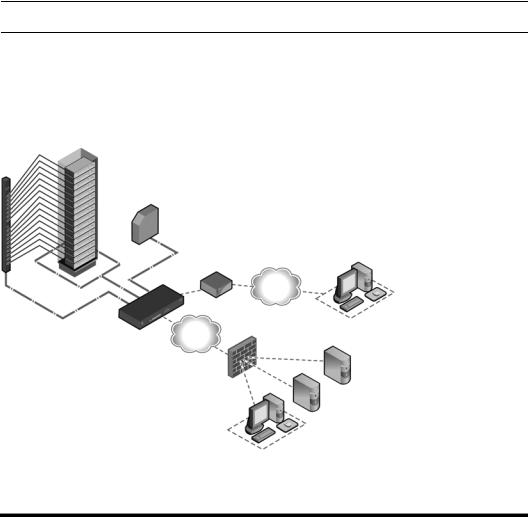
Configuration Example
The following graphic and table illustrate a typical ACS 6000 console server configuration.
3
2
5
4
7 |
9 |
6
4 |
8 |
|
1
10 11
12
13
14
Figure 1.1: Typical ACS 6000 Advanced Console Server Configuration
Table 1.1: Typical ACS 6000 Advanced Console Server Configuration Descriptions
Number |
Description |
Number |
Description |
|
|
|
|
1 |
ACS 6000 advanced console server |
8 |
Phone line |
|
|
|
|
2 |
Target devices |
9 |
Remote dial-in client |
|
|
|
|
3 |
PDU (one or more) |
10 |
Local Area Network (LAN) |
|
|
|
|

6 Cyclades ACS 6000 Advanced Console Server Installation/Administration/User Guide
Table 1.1: Typical ACS 6000 Advanced Console Server Configuration Descriptions (Continued)
Number |
Description |
Number |
Description |
|
|
|
|
4 |
Serial port connection |
11 |
LAN firewall |
|
|
|
|
5 |
PC card (modem, Ethernet or storage) |
12 |
Remote authentication server |
|
|
|
|
6 |
Either AUX/Modem or any serial port |
13 |
DSView client/server |
|
|
|
|
7 |
Modem ordered and configured internally at the factory |
14 |
Remote/local Windows/Linux |
|
-or- |
|
computer |
|
External modem (on a device in one of the PC card slots |
|
|
|
or USB port, or connected to a serial port or the AUX port) |
|
|
|
|
|
|

7
CHAPTER
2 Installation
Rack Mounting
You can mount the ACS 6000 console server in a rack or cabinet or place it on a desktop or other flat surface. For rack or cabinet mounting, two mounting brackets are supplied with six hex screws to connect the brackets to the console server. You will also need a Phillips screwdriver and the appropriate nuts and bolts to connect the mounting brackets to the rack.
To rack mount the console server:
1.Install the brackets at the front or back edges of the ACS 6000 console server with the screws provided with the mounting kit.
2.Mount the console server in a secure position.
Figure 2.1: Bracket Connections for Front Mount Configuration

8 Cyclades ACS 6000 Advanced Console Server Installation/Administration/User Guide
Connecting the Hardware
ACS console server connectors
The following figure shows the connectors on the front of the ACS 6000 console server.
1 |
2 |
3 |
Figure 2.2: Front of the Console Server with PC Card Slots and LEDs (ACS 6032 Console Server Shown)
Table 2.1: Connectors on the Console Server Front
Number Description
1USB connector. Supports the following USB devices: modem, wireless modem, storage and USB hub.
2LEDs. See Table 2.2.
3PC card slots. Supports modem (wireless V.92), Ethernet, Fast Ethernet and storage device PC cards.
Table 2.2: LEDs on the Console Server Front
Label |
Description |
|
|
PWR/CPU |
Blue |
|
• Blinks - During unit boot |
|
• Solid - During operation |
|
• Off - Power is off |
|
|
ETH 0/ETH 1 |
• Amber - Link at 10BaseT speed |
|
• Yellow - Link at 100BaseT speed |
|
• Green - Link at 1000BaseT speed |
|
• Off - No link/cable disconnected/Ethernet fault |
|
|
AUX/MODEM |
Dual LED: Yellow on top, green on bottom |
|
• Yellow - DTR/DCD activity |
|
• Green - TXD and RXD activity |
|
• Off - No activity |
[One LED for each serial port] Green
•Blinks - Ready, with activity
•Solid - Ready
•Off - Not ready
Chapter 2: Installation |
9 |
|
|
The following figure shows the rear connectors on the console server.
4
3
|
|
|
5 |
1 |
2 |
||
Figure 2.3: Rear of the Console Server (ACS 6032 Console Server Shown) |
|||
Table 2.3: Connectors on the Console Server Rear |
|||
|
|
|
|
Number |
Description |
||
|
|
|
|
1 |
|
Power supplies (dual AC shown). Models come with either single or dual AC or DC power. |
|
2Serial ports (32 ports shown). Models come with 16, 32 or 48 serial ports to connect to device consoles, power devices or external modems.
3ETH 1 10/100M/1G Ethernet port. Can be connected to a second network or used for failover.
4AUX/Modem port - if an optional internal modem is ordered, this port is defined as a V.92 modem at the factory and can be used to connect the console server to a dedicated phone line; otherwise, the port is factory-defined as RS-232 with an RJ-45 Cyclades pinout and can be used to connect either an external modem or a power device.
5ETH0 10/100M/1G Ethernet port for remote IP access.
6Console port allows for local administration and access to connected devices through a terminal or a computer with a terminal emulator.
Device consoles or modems to serial ports
Use CAT 5 or greater cables and DB-9 or DB-25 console adaptors as needed to connect target device consoles or modems to the serial ports on the console server.
The ACS 6000 console server supports two different serial port pinout configurations, Cyclades and Cisco®. The default is Cyclades. If a Cisco cable is connected to the port, the administrator must reconfigure the pinout for the port. The administrator selects Units - Appliance Settings - Ports - Physical Ports and selects the Cisco option from the RJ-45 Pinout drop-down menu.

10 Cyclades ACS 6000 Advanced Console Server Installation/Administration/User Guide
The following tables show serial port pinout information, which you can use to create cables.
Table 2.4: Cyclades Serial Port Pinout
Pin No. |
Signal Name |
Input/Output |
|
|
|
1 |
RTS |
OUT |
|
|
|
2 |
DTR |
OUT |
|
|
|
3 |
TxD |
OUT |
|
|
|
4 |
GND |
N/A |
|
|
|
5 |
CTS |
IN |
|
|
|
6 |
RxD |
IN |
|
|
|
7 |
DCD/DSR |
IN |
|
|
|
8 |
Not Used |
N/A |
|
||
Table 2.5: Cisco Serial Port Pinout |
||
|
|
|
Pin No. |
Signal Name |
Input/Output |
|
|
|
1 |
CTS |
IN |
|
|
|
2 |
DCD/DSR |
IN |
|
|
|
3 |
RxD |
IN |
|
|
|
4 |
GND |
N/A |
|
|
|
5 |
Not Used |
N/A |
|
|
|
6 |
TxD |
OUT |
|
|
|
7 |
DTR |
OUT |
|
|
|
8 |
RTS |
OUT |
|
|
|
To connect device consoles to serial ports:
Make sure the crossover cable used to connect a device has the same pinouts type that is configured in the software for the port (either Cyclades or Cisco).
1.Make sure the power switches on devices are turned off.
2.To connect the console ports of devices to the serial ports, use CAT 5 or greater crossover cables.

Chapter 2: Installation |
11 |
|
|
3.To connect modems, use straight-through CAT 5 or greater cables, with RJ-45 connectors on one end and the appropriate connectors or adaptors (USB, DB-9 or DB-25) for the modem on the other end.
See Power devices on page 11 for more information on connecting power devices.
See To install a pluggable device: on page 17 for more information on installing PC cards.
NOTE: To comply with EMC requirements, use shielded cables for all port connections.
WARNING: Do not turn on the power on the connected devices until after the console server is turned on.
Power devices
The following figure shows two daisy-chained Cyclades PDUs connected to serial port 2 on a console server.
Figure 2.4: Example: Daisy-chained Cyclades PDUs
To daisy-chain Cyclades PDUs to the console server:
This procedure assumes that you have one Cyclades PM PDU connected to a serial port on the console server.
NOTE: Daisy chaining is not possible with SPC PDUs. ServerTech PDUs will allow only one level (Master and Slave) of daisy chaining.

12Cyclades ACS 6000 Advanced Console Server Installation/Administration/User Guide
1.Connect one end of a UTP cable with RJ-45 connectors to the OUT port of the Cyclades PDU connected to the serial port on the console server.
2.Connect the other end of the cable to the IN port of the next Cyclades PDU.
3.Repeat steps 1 and 2 until you have connected the desired number of Cyclades PDUs.
NOTE: For performance reasons, Avocent recommends connecting no more than 128 outlets per serial port.
NOTE: If the outlet has been assigned a name, such as “myoutlet,” entering myoutlet is sufficient and no other path name is needed.
Power Configuration
The console server is supplied with single or dual AC or DC power supplies.
WARNING: Always execute the reboot command through the Web Manager or CLI under the Overview/Tools node before power cycling the appliance. This will ensure that the reset doesn't occur while the file system in Flash is being accessed and it helps avoiding Flash memory corruptions.
To configure AC power:
1.Make sure that the power switch on the console server is turned off.
2.Plug the power cable into the console server and into a power source.
3.Turn the console server on.
4.Turn on the power switches of the connected devices.
To configure DC power:
DC power is connected to DC-powered console servers by way of three wires: Return (RTN), Ground (GND) and -48 VDC.
WARNING: It is critical that the power source supports the DC power requirements of your console server. Make sure that your power source is the correct type and that your DC power cables are in good condition before proceeding. Failure to do so could result in damage to the equipment or in personal injury.
The following diagram shows the connector configuration for connecting DC power. You may use either a flat-blade or Phillips screwdriver for this procedure.

Chapter 2: Installation |
13 |
|
|
|
|
|
|
|
|
|
|
|
|
|
|
|
|
|
|
|
|
1 |
2 |
3 |
|
|
|
|
|
|
4 |
|
|
|
|||||
Figure 2.5: DC Power Connection Terminal Block |
|
|||||||
Table 2.6: DC Power Connection Details |
|
|
||||||
|
|
|
|
|
|
|
|
|
Number |
Description |
Number |
Description |
|||||
|
|
|
|
|
|
|
|
|
1 |
|
|
Power switch |
3 |
GND (Ground) |
|||
|
|
|
|
|
|
|
|
|
2 |
|
|
RTN (Return) |
4 |
-48 VDC |
|||
|
|
|
|
|
|
|
|
|
1.Make sure that the power switch on the console server is turned off.
2.Make sure that DC power cables are not connected to a power source.
3.Remove the protective cover from the DC power block by sliding it to the left or right.
4.Loosen all three DC power connection terminal screws.
5.Connect your return lead to the RTN terminal and tighten the screw.
6.Connect your ground lead to the GND terminal and tighten the screw.
7.Connect your -48 VDC lead to the -48 VDC terminal and tighten the screw.
8.Slide the protective cover back into place over the DC terminal block.
9.If your console server has dual-input DC terminals, repeat steps 3 - 8 for the second terminal.
10.Connect the DC power cables to the DC power source and turn on the DC power source.
11.Turn on the console server.
12.Turn on the power switches of the connected devices.
ACS 6000 Remote Console Server Configuration
You may make an Ethernet connection or a direct connection to access the remote console switch. For information on accessing the Web Manager and performing first time configuration steps, see
Using the Web Manager on page 15 and First Time Configuration on page 19.

14 Cyclades ACS 6000 Advanced Console Server Installation/Administration/User Guide
Making an Ethernet connection
To make an Ethernet connection, connect an Ethernet cable to the port labeled 10/100/1000Base-T and to an Ethernet hub or switch.
Making a direct connection
To connect a computer or terminal to the console port:
1.Connect a CAT 5 straight-through cable with RJ-45 connectors to one of the supplied RJ-45 adaptors.
2.Connect the RJ-45 end of the cable to the Console port on the console server.
3.Connect the adaptor end of the cable either to a terminal or a computer that has a terminal emulation program.
To configure network parameters:
1.Connect to the Console port using a terminal or computer with a terminal emulation program.
2.Make sure the terminal settings are: 9600, 8, N and 1, flow control None.
3.Log in to the console server as admin, with the default password avocent. The CLI prompt appears.
--|- units cli->
4.At the command prompt, enter wiz to view and/or change the current IP configuration.
--|- units cli-> wiz
5.Set the IP configuration for Eth0 by pressing Enter to maintain the current value, Tab + Tab to see the option(s) or Esc + Tab to see the current parameter value for editing.
eth0:
IPv4 Address: 172.26.30.241 IPv6 Address:
status : ipv4_method : ipv6_method :
MAC Address: 00:e0:86:0c:57:5d
dns:
primary : secondary : domain : hostname :
6.Type yes to confirm and save the new configuration.
Are all these parameters correct? (no, yes, quit) [no] :
NOTE: DHCP is the default IP configuration. A fixed IP address must be available for users to access the Web Manager.

Chapter 2: Installation |
15 |
|
|
Accessing an ACS Console Server
Using the Web Manager
An IP address is needed to launch the Web Manager in a browser. The IP address is usually configured as a static IP address assigned to the console server during initial configuration. If DHCP is used, then the user must be able to discover the IP address assigned by the DHCP server.
The console server ships with DHCP enabled. Users can access the Web Manager with either a DHCP-assigned IP address, an administrator-assigned static IP address or the default IP address (192.168.160.10). For information on how to log in, see To log into the Web Manager: on page 15.
If you do not configure a static address, if a DHCP server is not on the network or if it fails to discover the IP address of the console server, you can enter the default static IP/subnet mask addresses of 192.168.160.10/255.255.255.0 for eth0 and 192.168.161.10/255.255.255.0 for eth1.
To use the default IP address to access the Web Manager:
Both the desktop and the console server should be in the same physical network. Add the host route 192.168.160.10/32 to the Ethernet interface. The following example adds the route to eth0 on the console server on a Linux machine:
# route add - host 192.168.160.10 eth0
To log into the Web Manager:
1.Enter the IP address of the console server in the address field of a browser.
2.Enter your username and password.
NOTE: Username and password are case sensitive.
NOTE: After logging into the Web Manager for the first, you must complete the First Time Configuration screen. See First Time Configuration on page 19 for more information.
Using Telnet/SSH
An authorized user can use a Telnet or SSH client to make a connection directly to the console of a device if the following are true:
•The Telnet or SSH protocol is enabled in the selected security profile.
•The Telnet or SSH protocol is configured for the port.
•The Telnet or SSH client is available, and it is enabled on the computer from which the connection is made.
To view and connect to devices with the Web Manager:
1.Select Topology in the side navigation bar. The content area displays the name of the console server.
Loading...