


 Loading...
AutoView® Switch
Installer/User Guide/Guide d’installation et d’utilisation
For models: 1400, 1500 and 2000
Pour les modèles 1400, 1500 et 2000
INSTRUCTIONS
This symbol is intended to alert the user to the presence of important operating and maintenance (servicing) instructions in the literature accompanying the appliance.
DANGEROUS VOLTAGE
This symbol is intended to alert the user to the presence of uninsulated dangerous voltage within the product’s enclosure that may be of sufficient magnitude to constitute a risk of electric shock to persons.
POWER ON
This symbol indicates the principal on/off switch is in the on position.
POWER OFF
This symbol indicates the principal on/off switch is in the off position.
PROTECTIVE GROUNDING TERMINAL
This symbol indicates a terminal which must be connected to earth ground prior to making any other connections to the equipment.

AutoView→ 1400/1500/2000
Installer/User Guide
Avocent, the Avocent logo, The Power of Being There, AutoView, OutLook and OSCAR are registered trademarks of Avocent Corporation or its affiliates. All other marks are the property of their respective owners.
♥ 2006 Avocent Corporation. All rights reserved. 590-507-616C
USA Notification
Warning: Changes or modifications to this unit not expressly approved by the party responsible for compliance could void the user’s authority to operate the equipment.
Note: This equipment has been tested and found to comply with the limits for a Class A digital device, pursuant to Part 15 of the FCC Rules. These limits are designed to provide reasonable protection against harmful interference when the equipment is operated in a commercial environment. This equipment generates, uses and can radiate radio frequency energy and, if not installed and used in accordance with the instruction manual, may cause harmful interference to radio communications. Operation of this equipment in a residential area is likely to cause harmful interference in which case the user will be required to correct the interference at his own expense.
Canadian Notification
This digital apparatus does not exceed the Class A limits for radio noise emissions from digital apparatus set out in the Radio Interference Regulations of the Canadian Department of Communications.
Le présente appareil numérique n’émet pas de bruits radioélectriques dépassant les limites applicables aux appareils numériques de la classe A prescrites dans le Règlement sur le brouillage radioélectrique édicté par le Ministère des Communications du Canada.
Japanese Approvals
Safety and EMC Approvals and Markings
UL, FCC Class A, cUL, ICES Class A, CE, N, GS, IRAM, GOST, VCCI Class A, MIC Class A, C-Tick

iii
TABLE OF CONTENTS
List of Figures .................................................................................................................. |
v |
List of Tables.................................................................................................................. |
vii |
Chapter 1: Product Overview.......................................................................................... |
1 |
Features and Benefits ........................................................................................................................ |
1 |
Safety Precautions ............................................................................................................................. |
4 |
Chapter 2: Installation ..................................................................................................... |
5 |
Getting Started................................................................................................................................... |
5 |
Supplied with the AutoView switch............................................................................................. |
5 |
Rack Mounting Your AutoView Switch.............................................................................................. |
5 |
Installing the AutoView Switch .......................................................................................................... |
6 |
Connecting Users............................................................................................................................... |
8 |
Cascading AutoView Switches........................................................................................................... |
8 |
Adding Legacy Switches .................................................................................................................. |
10 |
Setting Up Your AutoView Switching System .................................................................................. |
13 |
Chapter 3: Basic Operations......................................................................................... |
15 |
Controlling Your System at the Analog Ports.................................................................................. |
15 |
Viewing and Selecting Ports and Servers ........................................................................................ |
15 |
Navigating the OSCAR Interface..................................................................................................... |
17 |
Configuring OSCAR Interface Menus ............................................................................................. |
19 |
Assigning server names ............................................................................................................ |
20 |
Assigning device types .............................................................................................................. |
21 |
Changing the display behavior................................................................................................. |
23 |
Setting the keyboard country code............................................................................................ |
24 |
Controlling the status flag ........................................................................................................ |
25 |
Setting console security ............................................................................................................ |
26 |
Displaying Version Information ...................................................................................................... |
30 |
Scanning Your System...................................................................................................................... |
31 |
Running System Diagnostics............................................................................................................ |
33 |
Broadcasting to Servers................................................................................................................... |
35 |
Changing Your Switch Mode ........................................................................................................... |
37 |

iv AutoView 1400/1500/2000 Installer/User Guide
Chapter 4: Advanced Operations ................................................................................. |
39 |
Using Administrator Privileges ....................................................................................................... |
39 |
Appendices..................................................................................................................... |
43 |
Appendix A: Flash Upgrades........................................................................................................... |
43 |
Appendix B: Technical Specifications ............................................................................................. |
48 |
Appendix C: Sun Advanced Key Emulation..................................................................................... |
50 |
Appendix D: Technical Support....................................................................................................... |
52 |
Index................................................................................................................................ |
53 |

v
LIST OF FIGURES
Figure 1.1: Example of an AutoView Switch Configuration ............................................................. |
3 |
Figure 2.1: AutoView Switch Horizontal Installation ...................................................................... |
6 |
Figure 2.2: Basic AutoView Switch Configuration .......................................................................... |
7 |
Figure 2.3: AutoView 2000 Switch Configuration with a Cascaded Switch .................................. |
10 |
Figure 2.4: AutoView 2000 Switch Configuration with Legacy KVM Switches ............................ |
11 |
Figure 2.5: AutoView Switch Configuration with AutoView 1400/1500/2000 Switches................. |
12 |
Figure 3.1: Example of Configured Main Dialog Box .................................................................... |
15 |
Figure 3.2: Setup Dialog Box .......................................................................................................... |
20 |
Figure 3.3: Names Dialog Box ........................................................................................................ |
20 |
Figure 3.4: Name Modify Dialog Box ............................................................................................. |
21 |
Figure 3.5: Devices Dialog Box ...................................................................................................... |
22 |
Figure 3.6: Device Modify Dialog Box ........................................................................................... |
22 |
Figure 3.7: Menu Dialog Box.......................................................................................................... |
23 |
Figure 3.8: Keyboard Box ............................................................................................................... |
24 |
Figure 3.9: Keyboard Warning Dialog Box .................................................................................... |
25 |
Figure 3.10: Flag Dialog Box ......................................................................................................... |
26 |
Figure 3.11: Set Position Flag ........................................................................................................ |
26 |
Figure 3.12: Security Dialog Box.................................................................................................... |
27 |
Figure 3.13: Version Dialog Box .................................................................................................... |
30 |
Figure 3.14: Target Selection Dialog Box....................................................................................... |
31 |
Figure 3.15: Target Version Dialog Box........................................................................................ |
31 |
Figure 3.16: Scan Dialog Box ......................................................................................................... |
32 |
Figure 3.17: Commands Dialog Box............................................................................................... |
33 |
Figure 3.18: Diagnostics Dialog Box.............................................................................................. |
34 |
Figure 3.19: Diagnostics Warning Dialog Box............................................................................... |
35 |
Figure 3.20: Broadcast Dialog Box ................................................................................................ |
36 |
Figure 3.21: Broadcast Enable Confirm/Deny Dialog Box ............................................................ |
37 |
Figure 3.22: Switch Dialog Box ...................................................................................................... |
38 |
Figure 4.1: Security Menu ............................................................................................................... |
39 |
Figure 4.2: Setup Menu (Administrator Only) ................................................................................ |
40 |
Figure 4.3: User Setup Menu (Administrator Only)........................................................................ |
40 |
Figure 4.4: User Edit Menu (Administrator Only).......................................................................... |
41 |

vi AutoView 1400/1500/2000 Installer/User Guide
Figure 4.5: User Access Menu (Administrator Only)...................................................................... |
42 |
Figure A.1: AVRIQ Status Dialog Box ............................................................................................ |
44 |
Figure A.2: AVRIQ Upgrade Dialog Box........................................................................................ |
45 |
Figure A.3: Version Dialog Box ...................................................................................................... |
45 |
Figure A.4: Target Selection Dialog Box ....................................................................................... |
46 |
Figure A.5: Target Version Dialog Box ......................................................................................... |
46 |
Figure A.6: AVRIQ Load Dialog Box............................................................................................. |
47 |

vii
LIST OF TABLES
Table 2.1: Legacy Switch Support ................................................................................................... |
10 |
Table 3.1: OSCAR Interface Status Symbols ................................................................................... |
16 |
Table 3.2: OSCAR Interface Navigation Basics............................................................................. |
17 |
Table 3.3: Setup Features to Manage Routine Tasks for Your Servers........................................... |
19 |
Table 3.4: OSCAR Interface Status Flags ...................................................................................... |
25 |
Table 3.5: Diagnostic Test Details ................................................................................................. |
34 |
Table B.1: Product Specifications .................................................................................................. |
48 |
Table C.1: Sun Key Emulation ........................................................................................................ |
50 |
Table C.2: PS/2-to-USB Keyboard Mappings................................................................................. |
51 |

viii AutoView 1400/1500/2000 Installer/User Guide
1
CHAPTER
Product Overview
1
Features and Benefits
The AutoView® 1400/1500/2000 switches integrate Avocent field-proven analog keyboard, video and mouse (KVM) switching technology with advanced cable management, flexible access for two simultaneous users and a patented, easy-to-use interface. This AutoView series of KVM switches conveniently supports all major server platforms and features powerful on-screen management for easy system configuration and server selection.
AVRIQ Intelligent Module
A benefit of the AutoView switch is the AVRIQ intelligent module. The AVRIQ module with CAT 5 design dramatically reduces cable clutter, while providing optimal resolution and video settings. The built-in memory of the AVRIQ module simplifies configuration by assigning and retaining unique server names and Electronic ID (EID) numbers for each attached server. The AVRIQ module is powered directly from the server and provides Keep Alive functionality even if the AutoView switch is not powered.
Each AutoView 2000 switch has 16 Avocent Rack Interface (ARI) ports for connecting AVRIQ modules. AutoView 1400 and 1500 switches provide eight ARI ports. Utilizing an AVRIQ module, you can attach additional switches to expand your AutoView switching system. This flexibility allows you to add capacity as your data center grows.
Multiplatform support
The AVRIQ modules available with the AutoView switch support PS/2, Sun™, USB and serial server environments. Using the OSCAR® graphical user interface in conjunction with these modules allows you to switch easily across platforms.
Two-User Share Mode
The AutoView 1400/1500/2000 switches feature a Share Mode function that allows two users to gain access to a primary server. The user configurable time-out feature allows you to determine the amount of time (up to 600 seconds) for the target to remain idle before the other user can take control of the target.

2 AutoView 1400/1500/2000 Installer/User Guide
OSCAR graphical user interface
AutoView switches use the OSCAR interface, which features intuitive menus to configure your switching system and select computers. Computers can be identified by unique name, EID or port number, allowing you to assign unique server names.
Security
The OSCAR interface allows you to protect your system with a screen saver password. After a user-defined time, the screen saver mode engages and access is prohibited until the appropriate password is entered to reactivate the system.
Operation modes
The OSCAR user interface provides convenient operation modes for easy system administration of the AutoView switch. These modes (Broadcast, Scan, Switch and Share) allow you to manage your switching activities. Chapter 3 explains these modes in detail.
Video
The AutoView switch provides optimal resolution for analog VGA, SVGA and XGA video. Achieve resolutions of up to 1600 x 1200 with a 100 foot (30 meter) cable. Resolutions will vary depending upon the length of cable separating your switch and servers.
NOTE: Resolutions above 1280 x 1024 may need to be manually set in the operating systems display settings. Distances up to 100 feet (30 meters) are subject to cable quality and environmental factors.
Plug and Play
The AutoView switch also supports Display Data Channel (DDC) Plug and Play, which automates
configuration of the monitor and is compliant with the VESA DDC2B standard.
Flash upgradable
Upgrade your firmware at any time through a simple update utility to ensure that your AutoView
switching system is always running the most current version available. Both the AutoView switch
and the AVRIQ modules are Flash upgradable. See Appendix A for more information.
Cascading expansion
Each AutoView switch supports up to 16 directly attached servers and can conveniently scale to support more. You can expand your system using cascadable Avocent products such as other AutoView or OutLook® switches. This extra “cascade” of units allows you to attach up to 256 servers in one system. See Chapter 2 for more information.
Local user accounts
The AutoView 1400/1500/2000 switches enable an administrator to configure up to four user accounts for use with the switch. These user accounts allow the administrator to restrict what ports
Chapter 1: Product Overview |
3 |
|
|
a class of user can access, as well as the name of the user account and password. See Chapter 4 for more information.
Integrated Access Cables
The AutoView 1400/1500/2000 switches also feature Integrated Access Cable (IAC) modules designed to provide the same ease of use as the AVRIQ module. Available in three different lengths, IAC modules are RJ-45 style cables that provide a reduced cost alternative to AVRIQ modules. IAC modules support PS/2 and USB connectivity. Contact your Avocent representative for more information.
NOTE: IAC modules are not upgradable.
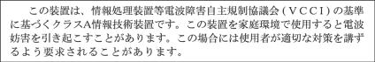
AVRIQ or IAC Module
|
AutoView Switch |
|
(Cascaded) |
Legacy Switch |
Rack of Servers |
(Cascaded) |
|
|
Critical Server |
Analog
Connection
AutoView Switch (Main)
Analog
Connection
Figure 1.1: Example of an AutoView Switch Configuration

4 AutoView 1400/1500/2000 Installer/User Guide
Safety Precautions
To avoid potential video and/or keyboard problems when using Avocent products:
•Ιf the building has 3-phase AC power, ensure that the computers and monitors are on the same phase. For best results, they should be on the same circuit.
•Use only Avocent-supplied cable to connect computers and KVM switches. Avocent warranties do not apply to damage resulting from user-supplied cable.
To avoid potentially fatal shock hazard and possible damage to equipment, please observe the following precautions:
•Do not use a 2-wire extension cord in any Avocent product configuration.
•Test AC outlets at the computer and monitor for proper polarity and grounding.
•Use only with grounded outlets at both the computer and monitor. When using a backup Uninterruptible Power Supply (UPS), power the computer, the monitor and the AutoView switch off the supply.
NOTE: The AC inlet is the main disconnect.
Rack mount safety considerations
•Elevated Ambient Temperature: If installed in a closed rack assembly, the operation temperature of the rack environment may be greater than room ambient. Use care not to exceed the rated maximum ambient temperature of the unit.
•Reduced Air Flow: Installation of the equipment in a rack should be such that the amount of airflow required for safe operation of the equipment is not compromised.
•Mechanical Loading: Mounting of the equipment in the rack should be such that a hazardous condition is not achieved due to uneven mechanical loading.
•Circuit Overloading: Consideration should be given to the connection of the equipment to the supply circuit and the effect that overloading of circuits might have on overcurrent protection and supply wiring. Consider equipment nameplate ratings for maximum current.
•Reliable Earthing: Reliable earthing of rack mounted equipment should be maintained. Pay particular attention to supply connections other than direct connections to the branch circuit (for example, use of power strips).

5
CHAPTER
Installation
2
Getting Started
Before installing your AutoView switch, refer to the following list to ensure you have all items that shipped with the AutoView switch, as well as other items necessary for proper installation.
Supplied with the AutoView switch
•Power cord
•One null modem serial cable
•Rack mounting kit
•AutoView 1400/1500/2000 Installer/User Guide
•AutoView 1400/1500/2000 Quick Installation Guide
Additional items needed
One IAC or AVRIQ module and CAT 5 cabling per attached server or switch
Rack Mounting Your AutoView Switch
Your AutoView switch may be rack mounted using the brackets supplied in your rack mounting kit. Before installing the switch and other components in the rack cabinet (if not already installed), stabilize the rack in a permanent location. Install your equipment starting at the bottom of the rack cabinet, then work to the top.
6 AutoView 1400/1500/2000 Installer/User Guide
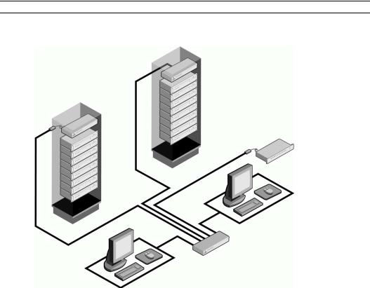
Figure 2.1: AutoView Switch Horizontal Installation
CAUTION: Rack Loading - Overloading or uneven loading of racks may result in shelf or rack failure, causing damage to equipment and possible personal injury. Do not exceed your rack load rating.
To install the 1U switch mounting bracket:
1.Remove the first two screws on each side of the switch.
2.Line up the holes in the “long side” of the kit’s side brackets with the screw holes in the switch.
3.With a Phillips screwdriver, fasten the mounting brackets to the switch using two screws on each side.
4.Attach four cage nuts or clip nuts to the rack mounting flange of the rack cabinet so that the nut is positioned on the inside of the rack.
NOTE: Nuts are not included with the rack mount kit.
5.Mount the switch assembly to the rack cabinet by matching the holes in the “short side” of each bracket to an appropriate set of matching holes on your rack cabinet.
6.Next, insert the combination hex head screws through the slots in the bracket and the holes in the mounting rail, then into the cage nuts or clip nuts.
Installing the AutoView Switch
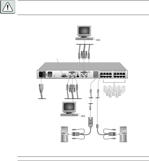
Plug the supplied power cord into the back of the appliance and then into an appropriate power source. Figure 2.2 illustrates one possible configuration for your AutoView switch. See the following detailed set of procedures to successfully install your appliance.
Chapter 2: Installation |
7 |
|
|
CAUTION: To reduce the risk of electric shock or damage to your equipment -
-Do not disable the power cord grounding plug. The grounding plug is an important safety feature.
-Plug the power cord into a grounded (earthed) outlet that is easily accessible at all times.
-Disconnect the power from the unit by unplugging the power cord from either the electrical outlet or the unit.
Analog User B
Configuration Port
(for updating firmware) AutoView Switch
Servers 3-16
Analog User A |
|
AVRIQ Module |
IAC Module |
Server 1 |
Server 2 |
Figure 2.2: Basic AutoView Switch Configuration
NOTE: Only the AutoView 1500 and the AutoView 2000 switches support two simultaneous users.

8 AutoView 1400/1500/2000 Installer/User Guide
To connect a server using an AVRIQ module:
1.Locate the AVRIQ modules for your AutoView switch.
2.Attach the appropriately color-coded cable ends to the keyboard, monitor and mouse ports on the first server you will be connecting to the appliance.
3.Attach one end of a CAT 5 cable to the RJ-45 connector on the AVRIQ module.
4.Connect the other end of the CAT 5 cable to the desired ARI port on the back of your AutoView switch.
5.Repeat steps 2 through 4 for each server you wish to attach.
NOTE: When connecting a Sun AVRIQ module, you must use a multi-sync monitor to accommodate Sun computers that support both VGA and sync-on-green or composite sync.
To connect a server using an IAC module:
1.Locate an IAC module for the server you wish to connect.
2.Attach the appropriately color-coded cable ends of the IAC module to the keyboard, monitor and mouse ports on the server you will be connecting to the switch.
3.Attach the other end of the IAC module to an open ARI port.
4.Repeat steps 1 through 3 for each server you wish to attach.
Connecting Users
To connect local peripherals:
1.Select the keyboard, monitor and mouse to be connected to local analog user A.
2.Locate the port set labeled A on the back of the appliance. Connect these peripherals to their respective ports.
3.Bundle and label the cables for easy identification.
4.Repeat these steps for user B, if desired.
Cascading AutoView Switches
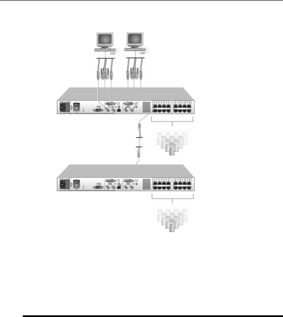
You can cascade multiple AutoView 1400/1500/2000 switches to enable one or two users to connect to as many as 256 servers. In a cascaded system, each ARI (Avocent Rack Interface) port on the main AutoView switch will connect to the ACI (Avocent Console Interface) port on each cascaded AutoView switch. Each cascaded switch can then be connected to a server with an AVRIQ module or IAC. The example shown in Figure 2.3 shows one AutoView switch cascaded under the main switch, enabling the connection of up to 15 primary servers and 16 secondary servers. Using this configuration, you could cascade 16 AutoView switches under the main switch, enabling the connection of up to 256 servers. Only one level of tiering is supported in this type of configuration, which means you cannot cascade any additional legacy switches or another AutoView switch.

Chapter 2: Installation |
9 |
|
|
In this configuration, the local port OSCAR interface is disabled in switches cascaded below the main AutoView switch.
To cascade multiple AutoView switches:
1.Connect the cascaded AutoView switch to each server as described in the previous Installing the AutoView Switch section.
2.Connect the local peripherals to analog user A and/or B of the main switch as described in To connect local peripherals.
3.Attach one end of the CAT 5 cabling that will run between your main and cascaded AutoView switch to the RJ-45 ACI port on the cascaded AutoView switch.
4.Attach the other end of the CAT 5 cable to one of the RJ-45 ARI ports on the main AutoView switch.
NOTE: The system will automatically “merge” the two switches together as one. All servers connected to the cascaded AutoView switch will display on the main AutoView switch server list in the OSCAR interface.
5.Repeat steps 3 and 4 for all additional (secondary) cascaded AutoView switches you wish to attach.
10 AutoView 1400/1500/2000 Installer/User Guide
Analog User A Analog User B
AutoView 2000 Switch
ARI Ports
15 Primary
Servers
AutoView 2000 Switch (cascaded)
ACI Port
16 Secondary
Servers
Figure 2.3: AutoView 2000 Switch Configuration with a Cascaded Switch
Adding Legacy Switches
You can add legacy switches to the AutoView switching system for easy integration into your existing configuration. In a cascaded system, each ARI port will accommodate up to 24 servers. See the following table for legacy switches compatible with the AutoView switching system.
Table 2.1: Legacy Switch Support
Legacy Product |
Model Numbers |
|
|
OutLook ES switch |
140ES, 180ES, 280ES, 1160ES, 2160ES, 4160ES |
|
|
AutoView switch |
AV200-4, AV200-8, AV400-4, AV400-8, AV416, AV424, AV1400, AV1500, AV2000 |
|
|
Chapter 2: Installation |
11 |
|
|
Local Analog User A
AutoView 2000 Switch
AVRIQ Module
PS/2, USB, Sun and serial
cables are available
AVRIQ Module
OutLook ES Switch |
AutoView 200/400 Switch |
Server 1
Server 2
Figure 2.4: AutoView 2000 Switch Configuration with Legacy KVM Switches
12 AutoView 1400/1500/2000 Installer/User Guide
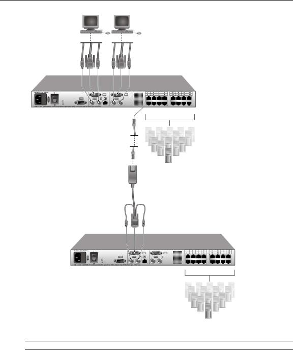
Local Analog User A
AVRIQ Module
PS/2, USB, Sun and serial modules are available
Local Analog User B
AutoView 1400/1500/2000 Switch
Secondary
Servers
AutoView 1400/1500/2000 Switch
Secondary
Servers
Figure 2.5: AutoView Switch Configuration with AutoView 1400/1500/2000 Switches
NOTE: The PS2IAC modules can be utilized in Figure 2.5.
Chapter 2: Installation |
13 |
|
|
To add a legacy KVM switch:
1.Mount the primary KVM switch into your rack cabinet.
2.Connect one end of a CAT 5 cable to an available port on the back of your AutoView switch.
3.Attach the keyboard, monitor and mouse connectors of the AVRIQ module to a user port on your cascaded switch.
4.Attach the other end of the CAT 5 cabling to the RJ-45 connector on the AVRIQ module.
5.Connect the servers to your cascaded switch according to the instructions included with the switch.
6.Power cycle the cascaded switch to enable its local user port to recognize the AVRIQ module.
7.Repeat steps 2 to 6 for all cascaded switches you wish to attach to your system.
To connect local peripherals:
1.Select the keyboard, monitor and mouse to be connected to local user A.
2.Locate the port set labeled A on the back of the switch. Connect these peripherals to their respective ports.
3.For the multiuser, 16-port AutoView switch, repeat steps 1 and 2 for the local analog port set
labeled B. - or -
For the AutoView 1400/1500 switch, proceed to step 4.
4.Bundle and label the cables for easy identification.
Setting Up Your AutoView Switching System
The AutoView switching system enables you to auto detect and configure each port on your appliance. Chapter 3 provides detailed instructions on name customization and OSCAR interface setup and configuration.

14 AutoView 1400/1500/2000 Installer/User Guide
15
CHAPTER
Basic Operations
3
Controlling Your System at the Analog Ports
The AutoView switch features one or two analog port sets on the back of the switch that allow you to connect a monitor and a PS/2 keyboard and mouse for direct analog access. The AutoView switch uses the OSCAR interface, featuring intuitive menus to configure your system and
select servers.
Viewing and Selecting Ports and Servers
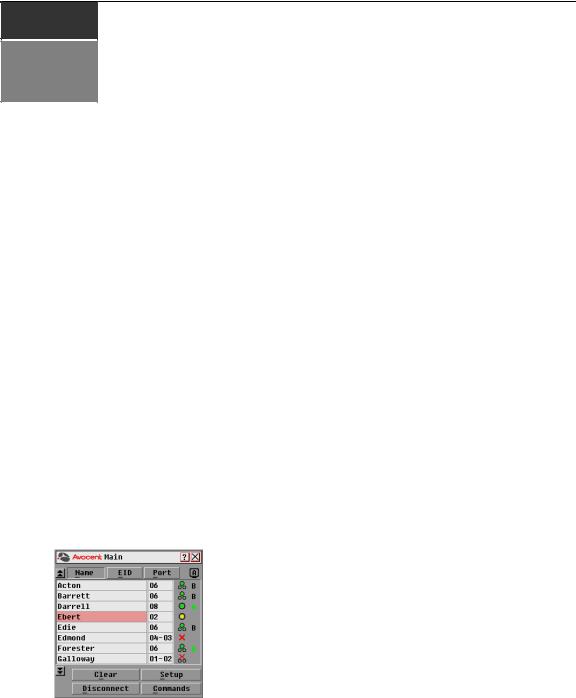
Use the OSCAR interface Main dialog box to view, configure and control servers in the AutoView switching system. View your servers by name, port or by the unique Electronic ID number (EID) embedded in each AVRIQ module and IAC. You will see an OSCAR interface-generated port list by default when you first launch the OSCAR GUI.
The Port column indicates the ARI port to which a server is connected. If you connect a legacy KVM switch to the main AutoView switch or a cascaded AutoView switch, the port numbering displays the ARI port first, then the switch port to which the server is connected. For example, in Figure 3.1, servers 04-03 and 01-02 are connected to switches, then to servers on ports 03 and 02 respectively.
To access the Main dialog box:
Press Print Screen to launch the OSCAR interface. The Main dialog box displays.
Figure 3.1: Example of Configured Main Dialog Box
16 AutoView 1400/1500/2000 Installer/User Guide
NOTE: You can also press the Control key twice, the Alt key twice or the Shift key twice within one second to launch the OSCAR interface. See Changing the display behavior later in this chapter for further details. You can use this key sequence in any place you see Print Screen throughout this installer/user guide.
Viewing the status of your switch
The status of the servers in your system is indicated in the right columns of the Main dialog box.
The following table describes the status symbols.
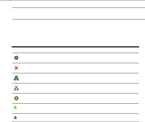
Table 3.1: OSCAR Interface Status Symbols
Symbol Description
AVRIQ modules and IACs are online (green circle).
AVRIQ modules and IACs are offline or are not operating properly.
Server is cascaded through a cascade legacy switch. The switch is online and has power.
Server is cascaded through a cascade legacy switch. The switch is offline or has no power.
AVRIQ module is being upgraded (yellow circle).
AVRIQ modules and IACs are being accessed by the indicated user channel (green channel letter).
AVRIQ modules and IACs are blocked by the indicated user channel (black channel letter).
Selecting servers
Use the Main dialog box to select servers. When you select a server, the switch reconfigures the keyboard and mouse to the proper settings for that server.
To select servers:
Double-click the server name, EID or port number. -or-
If the display order of your server list is by port (Port button is depressed), type the port number and press Enter.
-or-
If the display order of your server list is by name or EID number (Name or EID button is depressed), type the first few characters of the name of the server or the EID number to establish it as unique and press Enter.

Chapter 3: Basic Operations |
17 |
|
|
To select the previous server:
Press Print Screen and then Backspace. This key combination toggles you between the previous and current connections.
To disconnect the user from a server:
Press Print Screen and then Alt+0. This leaves the user in a free state, with no server selected. The status flag on your desktop displays Free.
Soft switching
Soft switching is the ability to switch servers using a hotkey sequence. You can soft switch to a server by pressing Print Screen and then typing the first few characters of its name or number. If you have set a Screen Delay Time and you press the key sequences before that time has elapsed, the OSCAR interface will not display.
To configure servers for soft switching:
1.Press Print Screen to launch the OSCAR interface. The Main dialog box displays.
2.Click Setup - Menu. The Menu dialog box displays.
3.For Screen Delay Time, type the number of seconds of delay desired before the Main dialog box is displayed after Print Screen is pressed.
4.Click OK.
To soft switch to a server:
1.To select a server, press Print Screen. If the display order of your server list is by port (Port button is depressed), type the port number and press Enter.
-or-
If the display order of your server list is by name or EID number (Name or EID button is depressed), type the first few characters of the name of the server or the EID number to establish it as unique and press Enter.
2.To switch back to the previous server, press Print Screen then Backspace.
Navigating the OSCAR Interface
This table describes how to navigate the OSCAR interface using the keyboard and mouse.
Table 3.2: OSCAR Interface Navigation Basics
This Keystroke |
Does This |
|
|
|
|
Print Screen,Ctrl-Ctrl |
Activates the OSCAR interface. See Changing the display behavior later in this |
|
Shift-Shift, and/or |
||
chapter for further details. |
||
Alt-Alt |
||
|
||
|
|
|
Print Screen-Print |
Press Print Screen twice to send the Print Screen keystroke to the currently |
|
Screen |
selected device. |
|
|
|

18 AutoView 1400/1500/2000 Installer/User Guide
Table 3.2: OSCAR Interface Navigation Basics (Continued)
This Keystroke |
Does This |
|
|
|
|
F1 |
Opens the Help screen for the current dialog box. |
|
|
|
|
|
Closes the current dialog box without saving changes and returns to the previous |
|
Escape |
one. In the Main dialog box, it closes the OSCAR interface and returns to the flag. In |
|
|
a message box, it closes the pop-up box and returns to the current dialog box. |
|
|
|
|
Alt+Hotkey |
Opens dialog boxes, selects or checks options and executes actions when used with |
|
underlined or other designated letters. |
||
|
||
|
|
|
Alt+X |
Closes the current dialog box and returns to the previous one. |
|
|
|
|
Alt+O |
Selects the OK button, then returns to the previous dialog box. |
|
|
|
|
Single-click, Enter |
In a text box, selects the text for editing and enables the Left and Right Arrow keys |
|
to move the cursor. Press Enter again to quit the edit mode. |
||
|
||
|
|
|
Enter |
Completes a switch in the Main dialog box and exits the OSCAR interface. |
|
|
|
|
Print Screen, |
Toggles back to previous selection. |
|
Backspace |
||
|
||
|
|
|
Print Screen, Alt+0 |
Immediately disengages a user from a server; no server is selected. Status flag |
|
(zero) |
displays Free. (This only applies to the 0 on the keyboard and not the keypad.) |
|
|
|
|
Print Screen, Pause |
Immediately turns on screen saver mode and prevents access to that specific |
|
console, if it is password protected. |
||
|
||
|
|
|
Up/Down Arrows |
Moves the cursor from line to line in lists. |
|
|
|
|
Right/Left Arrows |
Moves the cursor between columns. When editing a text box, these keys move the |
|
cursor within the column. |
||
|
||
|
|
|
Page Up/Page Down |
Pages up and down through Name and Port lists and Help pages. |
|
|
|
|
Home/End |
Moves the cursor to the top or bottom of a list. |
|
|
|
|
Delete |
Deletes characters in a text box. |
|
|
|
|
Page Up/Page Down |
Pages up and down through Name and Port lists and Help pages. |
|
|
|
|
Numbers |
Type from the keyboard or keypad. |
|
|
|
|
Print Screen, Ctrl+ F4 |
Logs the current user out of the switch (only available when Enable Local User |
|
Accounts is checked on the Security screen). |
||
|
||
|
|

Chapter 3: Basic Operations |
19 |
|
|
Configuring OSCAR Interface Menus
You can configure your AutoView switch from the Setup menu within the OSCAR interface. Select the Names button when initially setting up your switch to identify servers by unique names. Select the other setup features to manage routine tasks for your servers from the OSCAR interface menu.
Table 3.3: Setup Features to Manage Routine Tasks for Your Servers
Feature |
Purpose |
|
|
|
|
|
Change the server listing between numerically by port or EID number and |
|
Menu |
alphabetically by name. Change the Screen Delay Time before the OSCAR interface |
|
|
displays after pressing Print Screen. |
|
|
|
|
Flag |
Change display, timing, color or location of the status flag. |
|
|
|
|
Broadcast |
Set up to simultaneously control multiple servers through keyboard and |
|
mouse actions. |
||
|
||
|
|
|
Scan |
Set up a custom scan pattern for up to 16 servers. |
|
|
|
|
Security |
Set passwords to restrict server access. Enable the screen saver. |
|
|
|
|
Devices |
Identify the appropriate number of ports on an attached cascaded switch. |
|
|
|
|
Names |
Identify servers by unique names. |
|
|
|
|
Switch |
Choose the Switch Mode and the Share Mode time-out. |
|
|
|
|
Keyboard |
Choose the keyboard country code that is sent to the AVRIQ module and IAC. |
|
|
|
|
User |
Allows the administrator to set up the Local User Accounts (only visible when Enable |
|
Local User Accounts is checked on the Security screen). |
||
|
||
|
|
NOTE: Only the Menu, Flag and Security screens are available to the users without administrator privileges. All other screens, except the User screen, are available to the administrator when Enable Local User Accounts is disabled in the Security screen.
To access the Setup menu:
1.Press Print Screen to launch the OSCAR interface. The Main dialog box displays.
2.Click Setup. The Setup dialog box displays.
20 AutoView 1400/1500/2000 Installer/User Guide
Figure 3.2: Setup Dialog Box
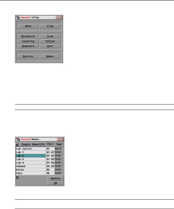
Assigning server names
Use the Names dialog box to identify individual servers by name rather than by port number. The Names list is always sorted by port order. Names are stored in the AVRIQ or IAC module, so even if you move the module/cable to another ARI port, the name and configuration will be recognized by the switch.
NOTE: If a server is turned off, its respective AVRIQ or IAC module will not appear in the Names list.
To access the Names dialog box:
1.Press Print Screen to launch the OSCAR interface. The Main dialog box will appear.
2.Click Setup - Names. The Names dialog box displays.
Figure 3.3: Names Dialog Box
NOTE: If the server list changes, the mouse cursor will turn into an hourglass as the list is automatically updated. No mouse or keyboard input will be accepted until the list update is complete.
Loading...