


CPS810

CPS
Installer/User Guide
CPS810
CPS1610
INSTRUCTIONS
This symbol is intended to alert the user to the presence of important operating and
maintenance (servicing) instructions in the literature accompanying the appliance.
DANGEROUS VOLTAGE
This symbol is intended to alert the user to the presence of uninsulated
dangerous voltage within the product’s enclosure that may be of sufficient
magnitude to constitute a risk of electric shock to persons.
POWER ON
This symbol indicates the principal on/off switch is in the on position.
POWER OFF
This symbol indicates the principal on/off switch is in the off position.
PROTECTIVE GROUNDING TERMINAL
This symbol indicates a terminal which must be connected to earth ground
prior to making any other connections to the equipment.

CPS810/1610
Installer/User Guide
Avocent, the Avocent logo, The Power of Being There and DSView are
registered trademarks of Avocent Corporation. All other marks are the
property of their respective owners.
© 2004 Avocent Corporation. All rights reserved.
USA Notification
Warning: Changes or modifications to this unit not expressly approved by the party responsible for compliance
could void the user’s authority to operate the equipment.
Note: This equipment has been tested and found to comply with the limits for a Class A digital device,
pursuant to Part 15 of the FCC rules. These limits are designed to provide reasonable protection against
harmful interference when the equipment is operated in a commercial environment. This equipment generates,
uses and can radiate radio frequency energy and, if not installed and used in accordance with the instruction
manual, may cause harmful interference to radio communications. Operation of this equipment in a residential
area is likely to cause harmful interference in which case the user will be required to correct the interference at
his own expense.
Canadian Notification
This digital apparatus does not exceed the Class A limits for radio noise emissions from digital apparatus set
out in the Radio Interference Regulations of the Canadian Department of Communications.
Le présent appareil numérique n’émet pas de bruits radioélectriques dépassant les limites applicables aux
appareils numériques de la classe A prescrites dans le Règlement sur le brouillage radioélectrique édicté par le
Ministère des Communications du Canada.
Japanese Approvals
Safety and EMC Standards
FCC P 15 Class A, EN55022, EN61000-3-2, EN61000-3-3, EN60950, EN55024, ETL (UL 1950), CSA 22.2
No. 950
This document is written for use with the CPS serial over IP network appliance application version 3.0 or later.
References to DSView
®
management software apply to version 3.0 or later.

TABLE OF CONTENTS
Table of Contents
List of Figures ................................................................................................................ vii
List of Tables ................................................................................................................... ix
Chapter 1: Product Overview.......................................................................................... 1
Features and Benefits ........................................................................................................................1
Safety Precautions .............................................................................................................................2
Using DSView Software.....................................................................................................................3
Chapter 2: Installation and Configuration ..................................................................... 5
Hardware Overview...........................................................................................................................5
Installing the CPS Network Appliance ..............................................................................................6
Configuring the CPS Appliance......................................................................................................... 7
Configuring the network addresses ............................................................................................ 7
Initial CPS appliance login ........................................................................................................9
Reinitializing the CPS Network Appliance ...................................................................................... 10
iii
Chapter 3: Operations ................................................................................................... 11
Overview .......................................................................................................................................... 11
Configuring Serial Port Settings...................................................................................................... 11
Connecting to Serial Devices........................................................................................................... 13
Connecting to devices using Telnet ..........................................................................................13
Connecting to devices from the serial CLI port........................................................................14
Configuring and using dial-in connections .............................................................................. 15
Connecting to devices using PPP.............................................................................................15
Connecting to devices using SSH .............................................................................................16
Enabling plain text Telnet and SSH connections...................................................................... 19
Telnet CLI mode ....................................................................................................................... 20
Ending Device Sessions ...................................................................................................................20
Session time-out........................................................................................................................21
Preemption................................................................................................................................ 21
Managing User Accounts.................................................................................................................22
Access rights and levels............................................................................................................23
Using Authentication Methods.........................................................................................................24

iv CPS Installer/User Guide
Authentication of serial CLI port sessions ............................................................................... 26
Authentication summary ...........................................................................................................26
Using security lock-out............................................................................................................. 27
Managing the Port History Buffer ...................................................................................................28
Using port history mode commands .........................................................................................28
Managing the CPS Appliance Using SNMP .................................................................................... 30
Chapter 4: Using CPS Appliance Commands ............................................................. 35
Accessing the CLI ............................................................................................................................35
Entering Commands ........................................................................................................................35
When commands take effect......................................................................................................36
Understanding Conventions ............................................................................................................ 36
Command syntax....................................................................................................................... 36
Syntax conventions....................................................................................................................38
Command Summary.........................................................................................................................38
Chapter 5: CPS Appliance Commands ........................................................................ 43
Connect Command...........................................................................................................................43
Disconnect Command ...................................................................................................................... 43
Help Command ................................................................................................................................44
Port Commands ............................................................................................................................... 44
Port Alert Add command ..........................................................................................................45
Port Alert Copy command ........................................................................................................45
Port Alert Delete command ......................................................................................................46
Port Break command ................................................................................................................ 46
Port History command..............................................................................................................46
Port Logout command .............................................................................................................. 47
Port Set command..................................................................................................................... 47
Port Set In/Out command .........................................................................................................49
Quit Command.................................................................................................................................50
Resume Command............................................................................................................................50
Server Commands ............................................................................................................................ 51
Server CLI command ................................................................................................................51
Server FLASH command .......................................................................................................... 53
Server Ping command............................................................................................................... 54

Table of Contents v
Server PPP command............................................................................................................... 54
Server RADIUS command ........................................................................................................55
Server Reboot command ...........................................................................................................56
Server Security command .........................................................................................................57
Server Set command ................................................................................................................. 57
Server SNMP command............................................................................................................ 58
Server SNMP Community command ........................................................................................58
Server SNMP Manager command ............................................................................................ 59
Server SNMP Trap command ...................................................................................................59
Server SNMP Trap Destination command ............................................................................... 60
Server SSH command ...............................................................................................................61
Show Commands.............................................................................................................................. 62
Show Port command.................................................................................................................62
Show Port Alert command ........................................................................................................ 64
Show Port In|Out command......................................................................................................64
Show Server command..............................................................................................................64
Show Server CLI command ......................................................................................................65
Show Server PPP command ..................................................................................................... 66
Show Server RADIUS command............................................................................................... 66
Show Server Security command................................................................................................ 66
Show Server SNMP command .................................................................................................. 67
Show User command ................................................................................................................ 67
SPC Command.................................................................................................................................69
User Commands...............................................................................................................................70
User Add command...................................................................................................................70
User Delete command...............................................................................................................72
User Logout command.............................................................................................................. 72
User Set command .................................................................................................................... 72
User Unlock command .............................................................................................................74
Appendices..................................................................................................................... 75
Appendix A: Technical Specifications .............................................................................................75
Appendix B: Device Cabling............................................................................................................77
Appendix C: Supported Traps.......................................................................................................... 82
Appendix D: Ports Used ..................................................................................................................85

vi CPS Installer/User Guide
Appendix E: Technical Support .......................................................................................................86
Index................................................................................................................................ 87

LIST OF FIGURES
List of Figures
Figure 2.1: 16-port CPS Appliance Front Panel .............................................................................. 5
Figure 2.2: 16-port CPS Appliance Back Panel................................................................................6
Figure B.1: CAT 5 Cable Adaptor Pin Assignments ....................................................................... 78
Figure B.2: Reversing Cable Adaptor Pin Assignments..................................................................80
Figure B.3: 8-wire RJ-45 Reversing Cable .....................................................................................81
vii

viii CPS Installer/User Guide

LIST OF TABLES
List of Tables
Table 2.1: LEDs and Buttons.............................................................................................................5
Table 3.1: Default Port Settings ..................................................................................................... 11
Table 3.2: SSH Authentication Methods..........................................................................................17
Table 3.3: Access Rights .................................................................................................................. 23
Table 3.4: Port History Mode Commands.......................................................................................28
Table 4.1: Line Editing Operations for VT100 Compatible Devices .............................................. 35
Table 4.2: Line Editing Operations for ASCII TTY Devices ...........................................................36
Table 4.3: Command Syntax Types in Example Command .............................................................36
Table 4.4: CPS Appliance Command Summary ..............................................................................38
Table 5.1: Connect Command Parameter ....................................................................................... 43
Table 5.2: Help Command Parameter.............................................................................................44
Table 5.3: Port Command Summary ...............................................................................................44
ix
Table 5.4: Port Alert Add Command Parameters ........................................................................... 45
Table 5.5: Port Alert Copy Command Parameters .........................................................................45
Table 5.6: Port Alert Delete Command Parameter ......................................................................... 46
Table 5.7: Port Logout Command Parameter .................................................................................47
Table 5.8: Port Set Command Parameters......................................................................................48
Table 5.9: Port Set In/Out Command Parameters ..........................................................................50
Table 5.10: Server Command Summary ..........................................................................................51
Table 5.11: Server CLI Command Parameters ...............................................................................52
Table 5.12: Server FLASH Command Parameters ......................................................................... 53
Table 5.13: Ping Command Parameter...........................................................................................54
Table 5.14: Server PPP Command Parameters .............................................................................. 55
Table 5.15: Server RADIUS Command Parameters .......................................................................56
Table 5.16: Server Security Command Parameters ........................................................................ 57
Table 5.17: Server Set Command Parameters.................................................................................58

x CPS Installer/User Guide
Table 5.18: Server SNMP Command Parameter............................................................................. 58
Table 5.19: Server SNMP Community Command Parameters........................................................ 59
Table 5.20: Server SNMP Manager Command Parameters ...........................................................59
Table 5.21: Server SNMP Trap Command Parameter....................................................................60
Table 5.22: Server SNMP Trap Destination Command Parameters...............................................61
Table 5.23: Server SSH Command Parameters...............................................................................61
Table 5.24: Show Command Summary............................................................................................ 62
Table 5.25: Show Port Command Parameter..................................................................................62
Table 5.26: Show Port Command Display Fields for Console Ports.............................................. 63
Table 5.27: Show Port Command Display Fields for SPC Ports.................................................... 63
Table 5.28: Show Port Alert Command Parameter.........................................................................64
Table 5.29: Show Server Command Display Fields ........................................................................64
Table 5.30: Show Server CLI Command Display Fields................................................................. 65
Table 5.31: Show Server Security Command Display Fields .......................................................... 67
Table 5.32 Show User Command Parameter .................................................................................. 68
Table 5.33: Show User Command Display Fields...........................................................................68
Table 5.34: Show User All Command Display Fields .....................................................................68
Table 5.35: SPC Command Parameters..........................................................................................69
Table 5.36: User Command Summary.............................................................................................70
Table 5.37: User Add Command .....................................................................................................71
Table 5.38: User Delete Command Parameter ...............................................................................72
Table 5.39: User Logout Command Parameter ..............................................................................72
Table 5.40: User Set Command Parameters ...................................................................................73
Table 5.41: User Logout Command Parameter ..............................................................................74
Table A.1: CPS 810/1610 Appliance Technical Specifications .......................................................75
Table B.1: Port Pin Assignments..................................................................................................... 77
Table B.2: Adaptors for Use with CAT 5 Cable .............................................................................. 77
Table B.3: Reversing Adaptors and Cables ....................................................................................79

List of Tables xi
Table C.1: CPS Appliance Enterprise Traps................................................................................... 82
Table D.1: Ports Used by CPS Appliance ....................................................................................... 85

xii CPS Installer/User Guide

CHAPTER
Product Overview
1
Features and Benefits
Overview
The CPS serial over IP network appliance provides non-blocked access and control for serial
devices such as routers, power management devices and firewalls. This includes Avocent SPC
power control devices that provide advanced power management and security.
You may connect up to 8 serial devices to a CPS810 appliance, and 16 serial devices to a CPS1610
appliance. A single 10/100 Ethernet port provides network connectivity. Two CPS appliances may
be mounted in 1U of vertical space in a standard 19 inch rack.
Serial device access options
1
You may choose from among several available Telnet options to access the CPS network appliance
and its attached serial devices:
•DSView
• Third party Telnet clients
Access to attached serial devices is also possible through a serial Command Line Interface (CLI)
connection, a PPP (Point to Point Protocol) dial-in connection to a serial CLI modem or from a
third party Secure Shell (SSH) client.
User authentication and data security
The CPS user database supports up to 64 user accounts, which include usernames, passwords and/or
keys, plus specifications of access rights to CPS appliance ports and commands. User definitions may
be changed at any time. You may choose to have user access authenticated locally at the CPS user
database, at one or more DSView software servers or at one or more RADIUS (Remote Access DialIn User Service) servers. Data security may be enhanced using industry-standard SSH encryption.
Extensive command set
The CPS network appliance offers a wide range of commands that allow administrators to easily
configure, control and display information about the CPS appliance operating environment,
including its ports, user accounts and active sessions. The user interface also offers descriptive
®
management software, which offers a built-in enhanced Telnet client

2 CPS Installer/User Guide
error message data and built-in command help information. On-board Trivial File Transfer Protocol
(TFTP) support allows administrators to upload new functionality to CPS appliances in the field.
Port history
Each CPS port has a buffer that holds the most recent 64K bytes of online and offline serial data. A
separate history command mode lets you navigate within a port’s current history file and conduct
tailored searches.
Safety Precautions
To avoid potential device problems when using Avocent products, if the building has 3-phase AC
power, ensure that a computer and its monitor (if used) are on the same phase. For best results, they
should be on the same circuit.
To avoid potentially fatal shock hazard and possible damage to equipment, please observe the
following precautions:
• Do not use a 2-wire extension cord in any Avocent product configuration.
• Test AC outlets at the computer and monitor (if used) for proper polarity and grounding.
• Use only with grounded outlets at both the computer and monitor. When using a backup Uninterruptible Power Supply (UPS), power the computer, the monitor and the CPS appliance off
the supply.
NOTE: The AC inlet is the main disconnect.
Rack mount safety considerations
• Elevated Ambient Temperature: If installed in a closed rack assembly, the operation temperature of the rack environment may be greater than room ambient. Use care not to exceed the
rated maximum ambient temperature of the unit.
• Reduced Airflow: Installation of the equipment in a rack should be such that the amount of airflow required for safe operation of the equipment is not compromised.
• Mechanical Loading: Mounting of the equipment in the rack should be such that a hazardous
condition is not achieved due to uneven mechanical loading.
• Circuit Overloading: Consideration should be given to the connection of the equipment to the
supply circuit and the effect that overloading of circuits might have on overcurrent protection
and supply wiring. Consider equipment nameplate ratings for maximum current.
• Reliable Earthing: Reliable earthing of rack mounted equipment should be maintained. Pay
particular attention to supply connections other than direct connections to the branch circuit
(for example, use of power strips).

Using DSView Software
The DSView management software may be used to manage CPS appliances and access attached
devices. Using DSView software, you may perform most of the operations that are described in this
manual. This manual describes how to manage a CPS appliance by entering commands using the
CLI. The DSView Installer/User Guide describes how to manage a CPS appliance using the
DSView software graphical interface.
Chapter 1: Product Overview 3

4 CPS Installer/User Guide
CHAPTER
Installation and Configuration
2
Hardware Overview
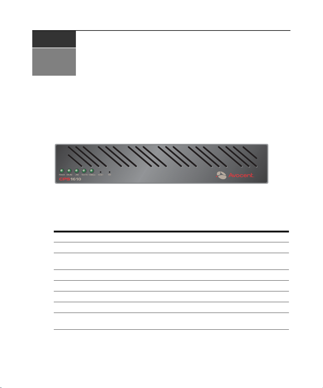
Figure 2.1 shows the front panel of a 16-port CPS network appliance.
Figure 2.1: 16-port CPS Appliance Front Panel
5
The lower left area of the front panel contains five LEDs and two buttons, which are described in
Table 2.1.
Table 2.1: LEDs and Buttons
LED/Button Description
POWER The POWER LED illuminates when the CPS appliance is connected to a power source.
ONLINE
LINK The LINK LED illuminates when the CPS appliance establishes a connection to the network.
TRAFFIC The TRAFFIC LED blinks when there is network traffic.
100MBps The 100MBps LED illuminates when the CPS appliance is connected to a 100 MBps LAN.
RESET The RESET button, when pressed, reboots the CPS appliance.
INIT
The ONLINE LED illuminates steadily (not blinking) when the CPS self-test and initialization
procedures complete successfully.
The INIT button, when pressed and held, restores the CPS appliance to factory defaults; for
more information, see Reinitializing the CPS Network Appliance on page 10.
6 CPS Installer/User Guide
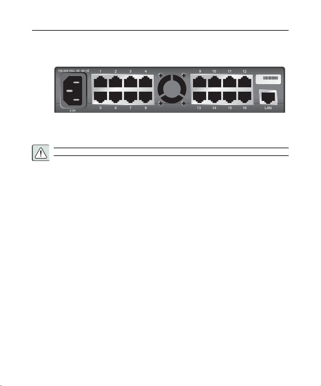
As shown in Figure 2.2, the back of the CPS appliance contains RJ-45 connectors for serial cabling
(8 connectors for an 8-port CPS appliance model or 16 connectors for a 16-port CPS appliance), a
LAN connector for a 10BaseT or 100BaseT interface cable and a power receptacle.
Figure 2.2: 16-port CPS Appliance Back Panel
Installing the CPS Network Appliance
WARNING: The power outlet should be near the equipment and easily accessible.
To install the CPS appliance hardware:
1. Place the unit where you can connect cables between the serial devices and the CPS serial
ports, and where you can connect a LAN interface cable between the Ethernet hub or switch
and the CPS LAN connector.
If you are using a rack mount kit, follow the instructions included with the kit.
2. Connect serial devices to the CPS serial ports; see Device Cabling on page 77 for cable
information. Connect each serial device to its appropriate power source, following the
device’s documentation.
3. Attach a 10BaseT or 100BaseT LAN interface cable to the LAN connector on the back of the
CPS appliance. A CAT 5 cable is required for 100BaseT operation.
4. Insert the power cord into the back of the unit. Insert the other end of the power cord into a
grounded electrical receptacle.
5. Check that the POWER LED is illuminated. If not, check the power cable to ensure that it is
inserted snugly into the back of the unit. The ONLINE LED will illuminate within one minute
to indicate that the self-test is complete. If the ONLINE LED blinks, contact Avocent
Technical Support for assistance.
6. Check that the LINK LED is also illuminated. If not, check the Ethernet cable to ensure that
both ends are correctly inserted into their jacks. If the unit is not correctly connected to an
Ethernet hub or switch, you will not be able to configure the appliance for operation. If the unit
is connected to a 100 MB Ethernet hub, the 100MBps LED will also be illuminated.
7. Once the POWER, ONLINE and LINK LEDs are illuminated, proceed with the configuration
process. (If you will be configuring the network address information with BootP, remove
power from the CPS appliance.)

WARNING: The CPS appliance and all attached devices should be powered down before servicing the unit.
Always disconnect the power cord from the wall outlet.
Configuring the CPS Appliance
To configure the CPS network appliance, you must specify a unique IP address, plus other network
address information. This information will be stored in the CPS configuration database. During
initial login, you will specify a password for the Admin user.
Configuring the network addresses
You may use any of four methods to configure the network information: DSView software, BootP,
Telnet Command Line Interface (CLI) or the serial CLI on port 1.
These methods work as documented on most Windows and UNIX systems; however, the actual
implementation on your system may differ from the instructions provided. Refer to your system
administrator guide.
To configure the network addresses using DSView software:
Using the DSView software installation wizard is the easiest method to configure the CPS
appliance IP address, subnet mask and gateway. See the DSView Installer/User Guide for
instructions. After the network addresses are configured, see Initial CPS appliance login on page 9.
Chapter 2: Installation and Configuration 7
To configure the network addresses using BootP:
1. Ensure that there is a BootP server on your network that is configured to correctly respond to a
BootP request from the CPS appliance. BootP servers require the Ethernet MAC address of
network devices. The Ethernet MAC address is located on the back panel above the LAN connector. See your BootP server’s system administrator guide for information about configuring
the BootP server.
2. After you have configured your network’s BootP server with the CPS appliance Ethernet MAC
address, IP address, subnet mask and gateway, restore power to the CPS appliance and wait for
the ONLINE LED to illuminate. Once this occurs, the CPS appliance has completed the BootP
protocol, obtained its IP address and subnet mask and stored these in FLASH.
3. You may verify that the BootP process was successful with a ping command, which tests network connectivity. The ping command is entered as:
ping <ip_address>
For example, the following command tests the network connectivity of a CPS appliance with
the IP address 192.168.0.5.
ping 192.168.0.5
4. If the CPS network appliance completes the BootP successfully, you will see a display similar
to the following.
Pinging 192.168.0.5 with 32 bytes of data:

8 CPS Installer/User Guide
Reply from 192.168.0.5: bytes=32 time<10ms TTL=128
Reply from 192.168.0.5: bytes=32 time<10ms TTL=128
Reply from 192.168.0.5: bytes=32 time<10ms TTL=128
Reply from 192.168.0.5: bytes=32 time<10ms TTL=128
If the CPS appliance did not successfully obtain its IP address with the BootP protocol, you
will see a display similar to the following.
Pinging 192.168.0.5 with 32 bytes of data
Request timed out.
Request timed out.
Request timed out.
Request timed out.
In this case, check the addresses provided to the BootP server to confirm they are correct.
Verify that the Ethernet LAN adaptor cable is correctly installed on the CPS appliance and the
Ethernet hub.
After the network addresses are configured successfully, launch a Telnet session to the assigned IP
address. Then, see Initial CPS appliance login on page 9.
To configure the network addresses using a Telnet CLI:
1. Ensure that your server or workstation has a Telnet client and is located on the same LAN segment as the CPS network appliance.
2. Use the arp command to update the server or workstation with the IP address and Ethernet
MAC address. The Ethernet MAC address is located on the back panel above the LAN connector. The arp command is entered as:
arp -s <ip_address> <mac_address>
For example, the following command assigns the IP address 192.168.0.5 and the Ethernet
MAC address 00-80-7d-54-01-54 to the CPS appliance.
arp -s 192.168.0.5 00-80-7d-54-01-54
On a UNIX platform, the MAC address may require colons (:) instead of dashes (-), for
example, 00:80:7d:54:01:54.
3. You may verify that you entered the information correctly by using an arp command with the
-a option.
arp -a
This command shows all arp entries for the server or workstation. See your system
administrator guide if you need additional help with the arp command.
4. After the above arp command is entered correctly, launch a Telnet client to the assigned IP
address. Then, continue with Initial CPS appliance login on page 9.
To configure the CPS appliance using the serial CLI:
1. By factory default, port 1 of the CPS appliance is configured for the serial CLI. To access the
serial CLI, attach a compatible device to port 1. The compatible device types are: ASCII,
VT52, VT100, VT102, VT220 and VT320.

For cable and adaptor information, see Device Cabling on page 77. You may also use any
terminal emulation program that is available on your system.
2. Configure your terminal or terminal emulation program as follows.
Baud rate 9600
Bits per character 8
Stop bits 1
Flow control None
3. Press the
Return or Enter key until a prompt appears, requesting your username. If you do not
receive a prompt after pressing the key five times, check your cable and serial settings to be
sure that they are correct.
4. Proceed to Initial CPS appliance login on page 9.
After you complete the CPS appliance configuration, you may reconfigure the CLI on another port
or disable it completely and use port 1 with an attached device. For more information, see
Connecting to devices from the serial CLI port on page 14.
Initial CPS appliance login
The CPS appliance ships with a single user defined in its user database. This predefined user has
the name Admin, no password and has the Appliance Administrator access level. The first time you
connect to the CPS network appliance, you are prompted for a username.
To log in to the CPS appliance for the first time:
Chapter 2: Installation and Configuration 9
1. At the Username prompt, type
user. At the Password prompt, press
Avocent CPS16xx S/W Version x.x (ASCII)
Username: Admin
Password:
Authentication Complete
CPS configuration is required.
Admin. There is no factory default password for the Admin
Return.
2. Once authentication completes, the CPS appliance prompts for any missing configuration values that are required for operation.
If you already provided the IP address, subnet mask and gateway, you will not be prompted for
those values again.
If you have not already provided the network information, you will be prompted for them.
Enter the addresses using standard dot notation.
CPS configuration is required
Enter CPS IP address > 192.168.0.5
Enter CPS Subnet mask > 255.255.255.0
Enter CPS Gateway address > 0.0.0.0
3. You are prompted for a new Admin password. Passwords are case sensitive and must contain
3-16 alphanumeric characters. You must enter the new password twice to confirm that you
entered it correctly.

10 CPS Installer/User Guide
Enter CPS New Admin Password > *****
Confirm New Admin Password > *****
After you have provided the required configuration information, a confirmation message appears
while the CPS appliance stores the values in its configuration database.
You have now completed the initial login, and you may enter additional commands at the CLI
prompt (>). To configure other CPS appliance ports, see Configuring Serial Port Settings on
page 11.
Reinitializing the CPS Network Appliance
Reinitializing the CPS appliance removes configured information. This may be useful when
reinstalling the unit at another location in your network.
The CPS appliance stores configuration information in FLASH databases. During reinitialization,
the FLASH erase has two phases. The first phase erases the configuration database, which contains
all nonvolatile data except the IP address. The second phase erases the IP address and restores the
CPS appliance to its factory default settings.
To reinitialize the CPS appliance:
1. Locate the recessed INIT button on the front of the CPS appliance. An opened paper clip may
be used to depress the button.
2. Insert the end of the opened paper clip in the recess, then depress and hold the button. The
ONLINE LED will blink, indicating an initialization has been requested. You have approximately seven seconds to release the button before any action is taken.
After seven seconds, the ONLINE LED will blink more rapidly to confirm that the CPS configuration database has been erased. Continuing to hold the INIT button for a few more seconds
will erase the IP address as well. The ONLINE LED will blink faster to confirm the deletion.
If any portion of FLASH is erased, the CPS appliance reboots when the INIT button is released.
You may also use the Server FLASH command to update the CPS FLASH application or boot
program. For more information, see Server FLASH command on page 53.

CHAPTER
Operations
3
Overview
The CPS serial over IP network appliance and its ports are easily configured and managed to meet
your requirements for device connection, user authentication, access control, power status
monitoring, port history information display and Simple Network Management Protocol (SNMP)
compliance for use with third party network management products. Support for SSH access using
third party clients is also provided.
Configuring Serial Port Settings
You may configure a CPS port to support one of two types of target devices (TDs): SPC and
console. The SPC power control device provides enhanced security options, including password
protection, port-specific access rights and port groupings. For more information, see the SPC
Installer/User Guide. A console TD may be a router, firewall, server or other supported serial device.
By default, ports are configured with the settings listed in Table 3.1.
11
Table 3.1: Default Port Settings
Parameter Value
Target device Console
Name xx-xx-xx Pn (last 3 octets of MAC address plus the port number)
Baud rate 9600
Bits per character 8
Parity None
Stop bits 1
Flow control None
Time-out 15 minutes
CLI access character User Server CLI setting (^D)

12 CPS Installer/User Guide
Table 3.1: Default Port Settings (Continued)
Parameter Value
Power None
Most of these settings are standard serial port operating characteristics.
The CLI access character parameter specifies how you access the CLI. For more information, see
Telnet CLI mode on page 20.
The Power parameter instructs the CCM appliance to monitor the state of a specified control signal.
Signal transitions may be configured to trigger SNMP traps. The parameter value indicates an
inbound control signal (CTS, DCD or DSR) and the state of that signal (low or high). When the
defined signal is true, the CPS appliance interprets it as a power on condition for the attached
device; when the signal is false, a power off condition for the device is assumed. The signal
specified for flow control may not be used for power control, and vice versa.
To configure serial console port settings:
Issue a Port Set command. You may specify settings for one or all ports.
PORT [<port>|ALL] SET TD=CONSOLE [NAME=<name>] [BAUD=<baud>]
[SIZE=<size>] [PARITY=<parity>] [STOP=<stop_bits>] [FLOW=<flow_ctrl>]
[TIMEOUT=<time-out>] [SOCKET=<socket>] [CHAR=^<cli_char>]
[TOGGLE=NONE|DTR] [POWER=<signal>]
To configure SPC ports and settings:
Issue a Port Set command with the TD=SPC parameter.
PORT <port> SET TD=SPC
When a port is configured as an SPC, you cannot change the serial port settings. However, you may
use the SPC command to change certain configuration values for the SPC and its individual sockets.
SPC <port>|ALL [MINLOAD=<amps>] [MAXLOAD=<amps>]
[SOCKET <socket>|ALL] [WAKE=ON|OFF] [ONMIN=<time>] [OFFmin=<time>]
For more information, see Port Set command on page 47 and SPC Command on page 69.
When you specify TD=SPC, you may configure the SPC device and control its individual sockets
using DSView software. Existing users who already have an SPC device and use its native
command interfaces should specify TD=Console.
To display serial port settings:
Issue a Show Port command.
SHOW PORT [<port>|ALL|NAMES]
When you request information about a console port, the display includes configuration information,
current power status (if power status monitoring has been enabled), plus transmit, receive and error
counts. When you request information about a single console port and a user is currently accessing

that port, the display also includes the username, access rights and other information about the
current session.
When you request information about a single SPC port, the display includes information configured
with the SPC command. A Show Port All command will indicate which ports are SPC ports.
When you request information about port names, the display includes the port numbers and names.
If a port’s name has not been changed with a Port Set command, the logical name is displayed.
For more information, see Show Port command on page 62.
Connecting to Serial Devices
The CPS network appliance offers several methods for connecting to attached serial devices:
Telnet, serial CLI, PPP and SSH.
Connecting to devices using Telnet
Each CPS serial port is directly addressable through a unique TCP port that provides a connection
to the attached serial device. You may connect using either SSH or plain text.
DSView management software
The Avocent DSView management software offers an interface to access devices attached to
Avocent digital Keyboard, Video and Mouse (KVM) appliances and CPS network appliances. The
Telnet client built into the DSView software uses Windows server-based authentication and
authentication servers to control access. Third party Telnet clients may also be supported with
DSView management software. For more information, see the DSView Installer/User Guide.
Chapter 3: Operations 13
Standalone third party Telnet clients
You may use third party Telnet clients to access the CPS appliance directly without DSView
management software.
To connect to a device using Telnet:
Type
telnet, followed by the CPS IP address and the appropriate TCP port, which by default is
3000 plus the physical port number, in decimal format. (The TCP port number may be changed for
any CPS port.)
For example, the following Telnet command connects to the serial device attached to physical port
14 of the CPS network appliance.
telnet 192.168.0.5 3014
If an authentication method other than None has been configured for the CPS appliance, you will be
prompted for a username and password. Once authentication completes, your connection is
confirmed. When you successfully connect to the serial device, you will see a display similar to
the following.
Avocent CPS ...
Username: Myname
Password: ******

14 CPS Installer/User Guide
Authentication Complete
Connected to Port: ...
If the authentication method is configured as None, you may Telnet and connect to a serial device
without entering credentials; however, credentials are always required when connecting to the
CPS CLI.
Data entered at the Telnet client is written to the attached serial device. Any data received by the
CPS appliance from the serial device is output to your Telnet client.
Connecting to devices from the serial CLI port
By factory default, port 1 of the CPS network appliance is configured with the serial CLI, which
prohibits the use of port 1 with an attached serial device. You may configure the CLI on a different
port, but only one port may be configured as the serial CLI port at one time. For example, if you
attempt to enable the CLI interface on port n, and it is already active on port p, then the CLI will
automatically be disabled on port p.
You may connect to one serial device at a time through the serial CLI port using a local terminal or
a local PC using a terminal emulation program. If you connect an external modem to the serial CLI
port, you may also access devices through a remote terminal or PC that can dial into the external
modem. For information about modem connections, see Connecting to devices using SSH on
page 16, Configuring and using dial-in connections on page 15 and Server CLI command on
page 51.
For more information about serial CLI port connections, see Authentication of serial CLI port
sessions on page 26 and Preemption on page 21.
To configure a port for the serial CLI:
1. Issue a Server CLI command, using the Port parameter to specify the CLI port and the Type
parameter to specify the terminal type.
SERVER CLI PORT=<port> TYPE=<type>
2. To disable the CLI that was previously configured on a port, issue a Server CLI command,
indicating Type=Off.
For more information, see Server CLI command on page 51.
To display CLI port information:
Issue a Show Server CLI command.
SHOW SERVER CLI
The display includes the CLI port number and terminal type, plus the CLI access character. For
more information, see Show Server CLI command on page 65.
To connect to a device from the serial CLI port:
1. Issue a Server CLI command, using the Connect parameter to enable the use of the Connect
command from the serial CLI port.
SERVER CLI CONNECT=ON

2. Issue a Connect command to the desired port.
CONNECT <port>
3. To end a device session that was initiated with a Connect command, issue a
Disconnect command.
DISCONNECT
For more information, see Server CLI command on page 51, Connect Command on page 43 and
Disconnect Command on page 43.
Configuring and using dial-in connections
You may attach an external modem to the serial CLI port for dial-in serial CLI access to the CPS
appliance. This may be used as a backup connection if the unit is not accessible from the network.
It may also be used as a primary connection at remote sites that do not have Ethernet network
capability. The modem must be Hayes compatible.
To specify a modem initialization string:
1. Issue a Show Server CLI command to ensure that the port where the modem is connected has
been defined as the serial CLI port.
SHOW SERVER CLI
2. Issue a Server CLI command, using the Modeminit parameter to specify the modem initialization string.
SERVER CLI MODEMINIT=“<string>”
The string must be enclosed in quotes and must include at least the command settings ATV1
and SO=1, which cause the modem to issue verbose response strings and auto-answer the
phone on the first ring. For more information, see Server CLI command on page 51.
The modem initialization string is sent to the cabled modem when any of the following
conditions occur:
• CPS appliance initialization
• Detection of a transition of DSR from low to high
• Completion of a call when DCD changes from high to low
3. Upon successful modem connection, press the
Chapter 3: Operations 15
Enter key until the login prompt appears.
To display modem configuration information:
Issue a Show Server CLI command.
SHOW SERVER CLI
For more information, see Show Server CLI command on page 65.
Connecting to devices using PPP
The CPS network appliance supports remote PPP access using an auto-answer modem that answers
calls and establishes the PPP protocol with a dial-in client.

16 CPS Installer/User Guide
The PPP dial-in may be used to access a remote CPS appliance that does not warrant a WAN (Wide
Area Network) link to the Ethernet interface. In this case, the PPP connection allows a remote PC
with Telnet capability to dial the CPS appliance and then establish a Telnet connection to a port.
The PPP dial-in may also be used to access a subnet containing remote CPS devices in the event of
a WAN link failure. In this case, the PPP provides an alternate path to one or more remote
CPS devices.
Once the PPP connection is established, you must launch an application that connects to the CPS
appliance or to one of its ports. The PPP connection is only a communications interface to the
CPS appliance.
The CPS appliance implements a PPP server that uses CHAP (Challenge Authentication Protocol).
Passwords are not accepted in the clear on PPP connections.
The authentication of PPP dial-in connections is not affected by enabling/disabling the server-level
CLI port authentication parameter. See Preemption on page 21 for more information.
To enable or disable a PPP server on the serial CLI port:
1. To enable a PPP server on the serial CLI port, issue a Show Server CLI command to ensure
that a serial CLI port has been defined.
SHOW SERVER CLI
2. Issue a Server PPP command with the Enable parameter.
SERVER PPP ENABLE LOCALIP=<local_ip> REMOTEIP=<rem_ip> [MASK=<subnet>]
You must specify local and remote IP addresses to be used for the CPS appliance and client
ends of the PPP connection respectively. You are prompted to confirm or cancel the changes.
Enter
Y to confirm or N to cancel.
3. To disable a PPP server, issue a Server PPP command with the Disable parameter.
SERVER PPP DISABLE
For more information, see Show Server CLI command on page 65 and Server PPP command on
page 54.
To display PPP configuration information:
Issue a Show Server PPP command.
SHOW SERVER PPP
For more information, see Show Server PPP command on page 66.
Connecting to devices using SSH
The CPS serial over IP network appliance supports version 2 of the SSH protocol (SSH2). The CPS
SSH server operates on the standard SSH port 22. The shell for this connection provides a CLI
prompt as if you had established a Telnet connection on port 23. The shell request for this
connection is for CLI access.
Additional CPS SSH servers operate on TCP ports that are numbered with values 100 greater than
the standard 30xx Telnet ports for the CPS appliance. For example, if port 7 is configured for
 Loading...