


1000R

Installer/User Guide
AutoView
®
1000R
AutoView
®
2000R
INSTRUCTIONS
This symbol is intended to alert the user to the presence of important operating and
maintenance (servicing) instructions in the literature accompanying the appliance.
DANGEROUS VOLTAGE
This symbol is intended to alert the user to the presence of uninsulated
dangerous voltage within the product’s enclosure that may be of sufficient
magnitude to constitute a risk of electric shock to persons.
POWER OFF
This symbol indicates the principal on/off switch is in the off position.
POWER ON
This symbol indicates the principal on/off switch is in the on position.
PROTECTIVE GROUNDING TERMINAL
This symbol indicates a terminal which must be connected to earth ground
prior to making any other connections to the equipment.
AutoView
®
1000R
AutoView
®
2000R
Installer/User Guide
Avocent, the Avocent logo, The Power of Being There,
AutoView, AVWorks, Outlook and OSCAR are trademarks or
registered trademarks of Avocent Corporation or its affiliates.
All other marks are the property of their respective owners.
© 2003 Avocent Corporation. All rights reserved.

USA Notification
Warning: Changes or modifications to this unit not expressly approved by the party
responsible for compliance could void the user's authority to operate the equipment.
Note: This equipment has been tested and found to comply with the limits for a Class A
digital device, pursuant to Part 15 of the FCC Rules. These limits are designed to provide
reasonable protection against harmful interference when the equipment is operated in a
commercial environment. This equipment generates, uses and can radiate radio
frequency energy and, if not installed and used in accordance with the instruction
manual, may cause harmful interference to radio communications. Operation of this
equipment in a residential area is likely to cause harmful interference in which case the
user will be required to correct the interference at his own expense.
Canadian Notification
This digital apparatus does not exceed the Class A limits for radio noise emissions from
digital apparatus set out in the Radio Interference Regulations of the Canadian
Department of Communications.
Le présent appareil numérique n’émet pas de bruits radioélectriques dépassant les
limites applicables aux appareils numériques de la classe A prescrites dans le Règlement
sur le brouillage radioélectrique édicté par le Ministère des Communications du Canada.
Japanese Approvals
Taiwanese Approvals
Agency Approvals
EN55022 Class A, EN55024, EN61000-3-3, FCC15 Class A, VCCI Class A, IEC950,
EN60950, UL 1950/60950 third edition, CSA C22.2 No. 950, E-E011-02-2836 (A),
CNS 13438

Table of Contents
Chapter 1: Product Overview
Features and Benefits . . . . . . . . . . . . . . . . . . . . . . . . . 3
Safety Precautions . . . . . . . . . . . . . . . . . . . . . . . . . . . 5
Chapter 2: Installation
Getting Started . . . . . . . . . . . . . . . . . . . . . . . . . . . . . . 9
Rack Mounting Your AutoView 1000R/2000R . . . 10
Installing the AutoView 1000R/2000R . . . . . . . . . . 11
Adding Servers . . . . . . . . . . . . . . . . . . . . . . . . . . . . . 16
Chapter 3: Local Port Operation
Controlling Your System at the Local Port . . . . . . 19
Viewing and Selecting Ports and Servers . . . . . . . . 19
Navigating OSCAR . . . . . . . . . . . . . . . . . . . . . . . . . 21
Configuring OSCAR . . . . . . . . . . . . . . . . . . . . . . . . 22
Assigning Server or Serial Device Names . . . . . . . 23
Assigning Device Types . . . . . . . . . . . . . . . . . . . . . . 25
Changing the Display Behavior . . . . . . . . . . . . . . . 26
Controlling the Status Flag . . . . . . . . . . . . . . . . . . . 27
Broadcasting to Servers . . . . . . . . . . . . . . . . . . . . . . 29
Using Scan Mode . . . . . . . . . . . . . . . . . . . . . . . . . . . 30
Setting Console Security . . . . . . . . . . . . . . . . . . . . .32
Setting the Keyboard Country Code . . . . . . . . . . . . 34
Managing Server Tasks Using OSCAR . . . . . . . . .35
Viewing and Disconnecting User Connections . . .36
Running System Diagnostics . . . . . . . . . . . . . . . . . 37
Resetting Your PS/2 Keyboard and Mouse . . . . . . 39
Displaying Version Information . . . . . . . . . . . . . . . 40
Chapter 4: Terminal Operations
Configuring the Terminal Applications Menu . . . 45
Appendices
Appendix A: FLASH Upgrades . . . . . . . . . . . . . . . . 49
Appendix B: Using AVRIQ-SRL Modules . . . . . . . 53
Appendix C: Unshielded Twisted Pair
(UTP) Cabling . . . . . . . . . . . . . . . . . . . . . . . . . . 58
Appendix D: Technical Specifications . . . . . . . . . . 60
Appendix E: Sun Advanced Key Emulation . . . . . 62
Appendix F: Technical Support . . . . . . . . . . . . . . . 64


Contents
Features and Benefits . . . . . . . . . . . . . . . . . . . . . . . . . 3
Safety Precautions . . . . . . . . . . . . . . . . . . . . . . . . . . . 5
1
Product Overview

Chapter 1: Product Overview 3
Chapter 1: Product Overview
Features and Benefits
The Avocent AutoView
®
1000R and 2000R model switches combine analog and
digital technology to provide flexible, centralized control of data center
servers. This solution delivers secure digital access and flexible server
management from anywhere at any time.
NOTE: Throughout the documentation you will see the word “ appliance” used generically to
describe the AutoView 1000R/2000R switch.
The AutoView 1000R/2000R consists of a rack mountable keyboard, video and
mouse ( KVM) switch configurable for analog (local) and digital (remote)
connectivity. Each AutoView 1000R/2000R has 16 Avocent Rack Interface
( ARI) ports for connecting devices and operating over standard LAN
connections. Access servers or serial devices across a 100BaseT Ethernet
connection or directly through a local port on the AutoView 1000R/2000R for
analog KVM connectivity and administration. Video resolutions through the
local port can be up to 1600 x 1280 with an end-to-end cable length of up to 15
meters (50 feet). Remote users can achieve video resolution of up to
1280 x 1024 with a cable length of up to 10 meters (32 feet) between the
AutoView 1000R/2000R and the server.
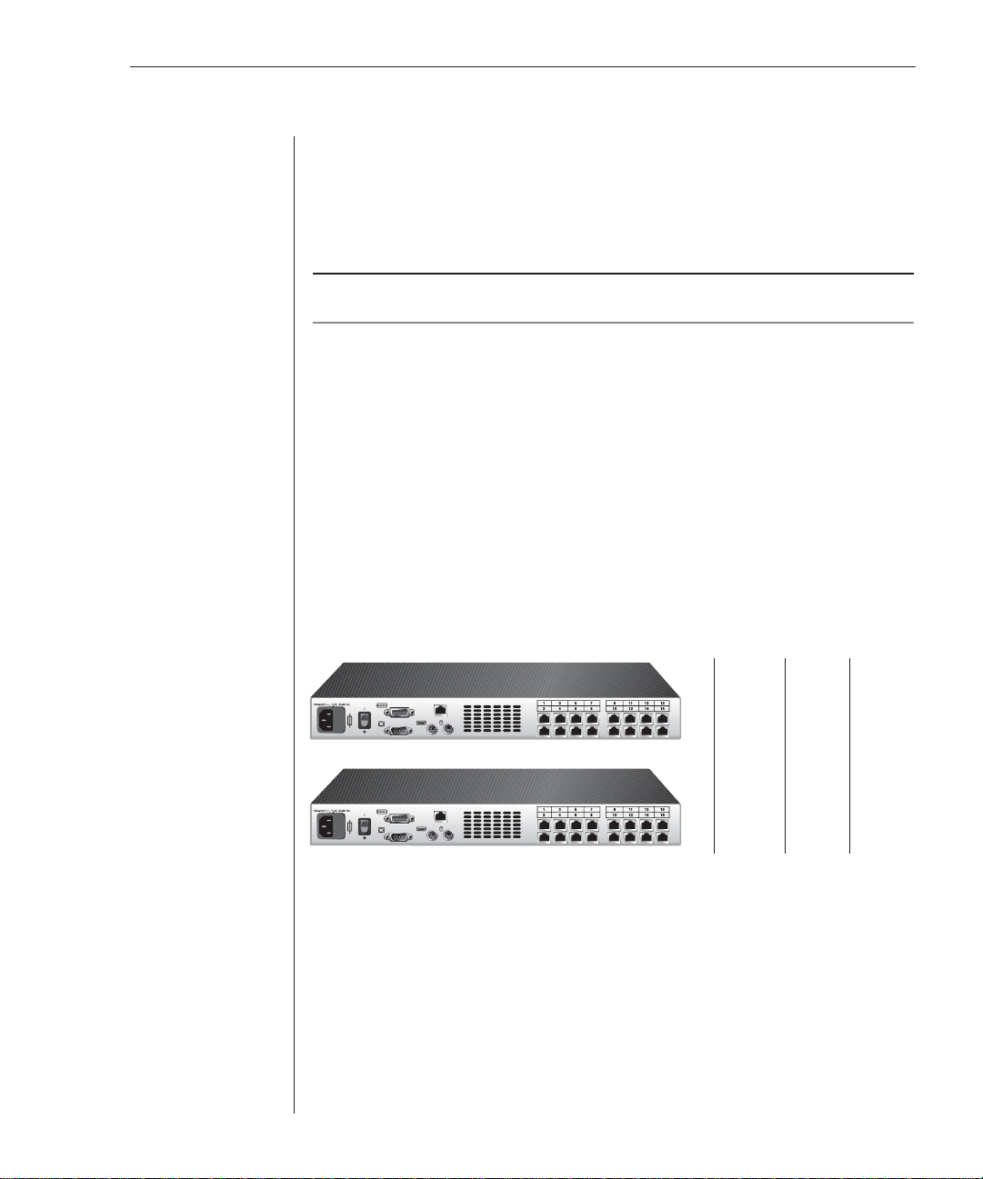
Figure 1.1: AutoView 1000R/2000R Model Comparison
AVRIQ and AVRIQ-SRL (serial) modules
The AVRIQ and AVRIQ-SRL (serial) modules with CAT 5 design dramatically
reduce cable clutter, while providing optimal digital display resolution and
video settings. The built-in memory of the AVRIQ simplifies configuration by
assigning and retaining unique server names or Electronic ID ( EID) numbers
for each attached server. This integrated intelligence enhances security and
prevents unauthorized access to a server through module manipulation. The
AVRIQ is powered directly from the server and provides Keep Alive
functionality even if the AutoView 1000R/2000R is not powered.
LAN
LAN
AutoView 1000R
AutoView 2000R
Number
of
servers
Digital
users
Analog
user
16
1
1
16
2
1

4 AutoView 1000R/ AutoView 2000R Installer/User Guide
The AVRIQ-SRL (serial) module is a DCE device that provides the primary
interface between a serial device and the AutoView 1000R/2000R appliance. It
provides VT100 terminal emulation, break suppression and port history in a
convenient module format. The AVRIQ-SRL is compatible with the ARI ports of
the AutoView 1000R/2000R appliance. See Appendix B for more information on
the AVRIQ-SRL module.
Access via network connection
No special software or drivers are required on the attached computers. Remote
users access the AutoView 1000R/2000R and all attached systems via Ethernet
from a PC running AVWorks
™
. This software resides on the user’s PC only. User
PCs can be located anywhere a valid network connection exists. The AutoView
1000R/2000R can be configured on a separate network from your data network,
allowing access to your servers even if your applications network is down.
Point and click control with AVWorks software
The AVWorks software is a cross-platform management application that allows
you to view and control the AutoView 1000R/2000R and all attached servers.
The AVWorks software provides secure authentication, data transfers and
username/ password storage. By utilizing a browser interface for navigation
with an intuitive split-screen interface, this software provides you with a single
point of access for your entire system. From here, you can manage the
AutoView 1000R/2000R, install a new AutoView 1000R/2000R or launch a video
session to a system server. Multiple servers can be accessed by one user; each
additional computer’s video will appear in a separate program window.
NOTE: Throughout the documentation and AVWorks user interface, you will see the word
“ appliance” used generically to describe the AutoView 1000R/2000R sw itch .
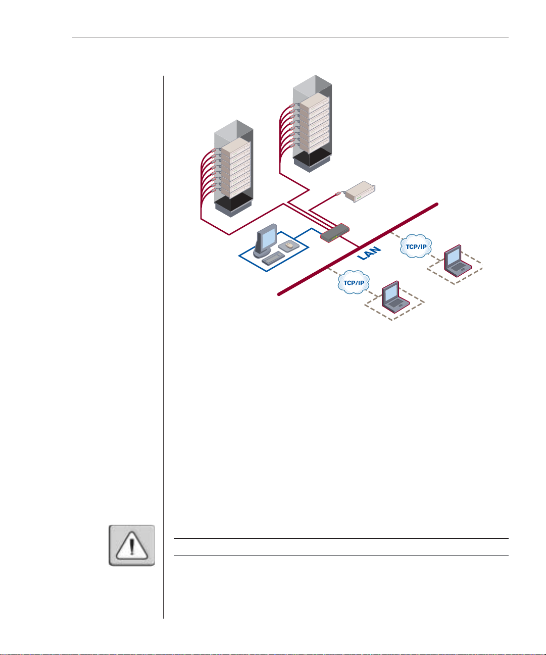
Chapter 1: Product Overview 5
Figure 1.2: Example AutoView 2000R Configuration
Safety Precautions
To avoid potential video and/or keyboard problems when using Avocent products:
• If the building has 3-phase AC power, ensure that the computer and monitor
are on the same phase. For best results, they should be on the same circuit.
To avoid potentially fatal shock hazard and possible damage to equipment,
please observe the following precautions:
• Do not use a 2-wire extension cord in any Avocent product confi guration.
• Test AC outlets at the computer and monitor for proper polarity and grounding.
• Use only with grounded outlets at both the computer and monitor. When
using a backup Uninterruptible Power Supply (UPS), power the computer,
the monitor and the appliance off the supply.
NOTE: The AC inlet is the main disconnect.
AVRIQ
Modules
AVRIQ
Modules
Rack
of
Servers
Rack
of
Servers
Critical Server
AutoView 2000R
Analog Connection
IP Connections

6 AutoView 1000R/ AutoView 2000R Installer/User Guide
Rack mount safety considerations
• Elevated Ambient Temperature: If installed in a closed rack assembly, the
operation temperature of the rack environment may be greater than room
ambient. Use care not to exceed the rated maximum ambient temperature
of the appliance.
• Reduced Air Flow: Installation of the equipment in a rack should be such
that the amount of airfl ow required for safe operation of the equipment is
not compromised.
• Mechanical Loading: Mounting of the equipment in the rack should be such
that a hazardous condition is not achieved due to uneven mechanical loading.
• Circuit Overloading: Consideration should be given to the connection of
the equipment to the supply circuit and the effect that overloading of
circuits might have on overcurrent protection and supply wiring. Consider
equipment nameplate ratings for maximum current.
• Reliable Earthing: Reliable earthing of rack mounted equipment should be
maintained. Pay particular attention to supply connections other than
direct connections to the branch circuit (for example, use of power strips).
UTP cables
The AutoView 1000R/2000R will function correctly with any combination of
CAT 5, CAT 5e and CAT 6 cables.
NOTE: Throughout this manual, the generic term “CAT 5” refers to any CAT cable used by the
AutoView 1000R/2000R appliance.

Contents
Getting Started . . . . . . . . . . . . . . . . . . . . . . . . . . . . . . 9
Rack Mounting Your AutoView 1000R/2000R . . . 10
Installing the AutoView 1000R/2000R . . . . . . . . . . 11
Adding Servers . . . . . . . . . . . . . . . . . . . . . . . . . . . . . 16
2
Installation


Chapter 2: Installation 9
Chapter 2: Installation
The AutoView 1000R/2000R appliance requires that the AVWorks software be
installed prior to use. AVWorks software allows you to view and control a
server attached to the AutoView 1000R/2000R appliance, configure and
maintain the system and prevent unauthorized access to the appliance via
IP connection.
NOTE: The local port does not require the AVWorks software for operation. The local port
uses the On-Screen Confi guration and Activity Reporting interface (OSCAR
®
). For more
information, see Chapter 3.
The AutoView 1000R/2000R appliance uses Ethernet networking
infrastructure and TCP/IP protocol to transmit keyboard, video and mouse
information between operators and connected computers. Although 10BaseT
Ethernet may be used, a dedicated, switched 100BaseT network provides
improved performance.
Getting Started
Before installing your AutoView 1000R/2000R appliance, refer to the following
lists to ensure you have all items that shipped with the appliance as well as
other items necessary for proper installation.
Supplied with the AutoView 1000R/2000R
The following items are supplied with your appliance:
• AutoView 1000R or AutoView 2000R appliance
• Power cord
• Rack mounting kit
• One straight-through null modem serial cable
• AutoView 1000R/2000R Installer/User Guide
• AVWorks Installer/User Guide
• AVWorks CD
• AutoView 1000R/2000R and AVWorks Quick Installation Guide
Additional items needed
The following are additional items needed to use your appliance:
• One AVRIQ per attached server or switch
• One AVRIQ-SRL per attached serial device
• One CAT 5 patch cable per server or serial device (4-pair UTP, up to
10 meters)
10 AutoView 1000R/ AutoView 2000R Installer/User Guide
Setting up your network
The AutoView 1000R/2000R appliance uses IP addresses to uniquely identify
the appliances and the computers running AVWorks software. The AutoView
appliance supports both BootP (a subset of DHCP) and static IP addressing.
Avocent recommends that IP addresses be reserved for each appliance and
that they remain static while the appliances are connected to the network.
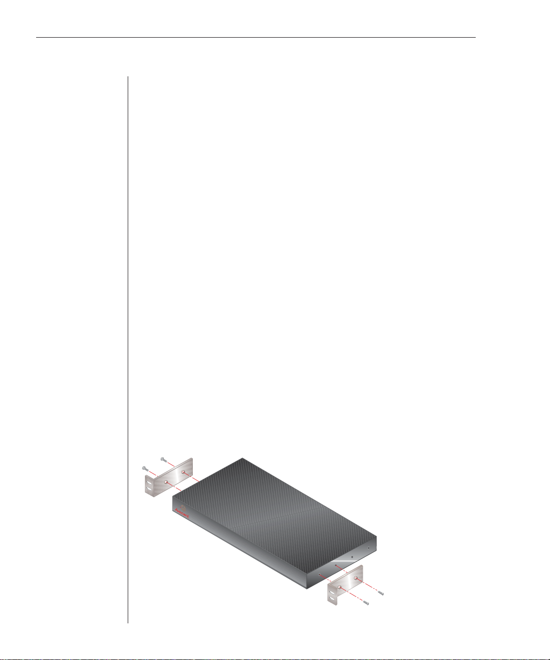
Rack Mounting Your AutoView 1000R/2000R
Your AutoView 1000R/2000R appliance ships with rack mounting brackets for
easy integration into your rack. Before installing the appliance and other
components in the rack cabinet (if not already installed), stabilize the rack in a
permanent location. Install your equipment starting at the bottom of the rack
cabinet, then work to the top. Avoid uneven loading or overloading of
rack cabinets.
To install the 1U switch mounting bracket:
1. Line up the holes in the “long side” of the kit’s side brackets with the
screw holes in the switch.
2. With a Phillips screwdriver, fasten the mounting brackets to the switch
using two 8/32 ” x 1//2 ” pan head screws on each side.
3. Attach the four cage nuts or clip nuts to the rack mounting fl ange of the
rack cabinet so that the nuts are positioned on the inside of the rack.
4. Mount the switch assembly to the rack cabinet by matching the holes in
the “short side” of each bracket to an appropriate set of matching holes on
your rack cabinet. Next, insert the combination hex head screws through
the slots in the bracket and the holes in the mounting rail, then into the
cage nuts or clip nuts.
Figure 2.1: AutoView 1000R/2000R Horizontal Installation
Chapter 2: Installation 11
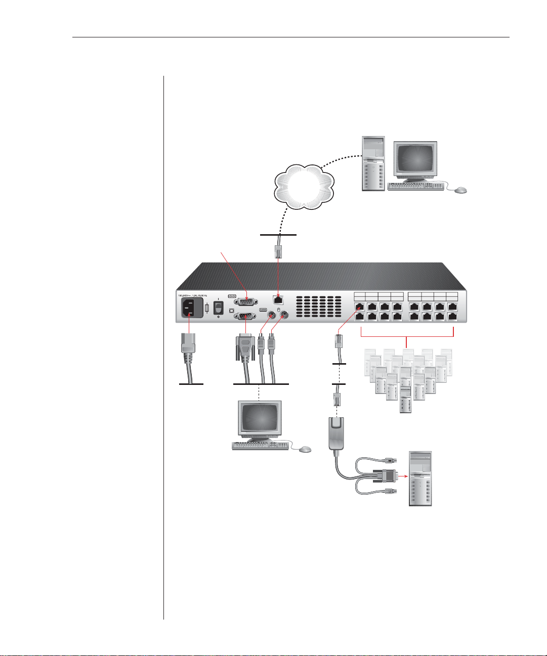
Installing the AutoView 1000R/2000R
Figure 2.2 illustrates one possible configuration for your AutoView 1000R/
2000R appliance. Follow the detailed set of procedures following Figure 2.2 to
successfully install your appliance.
1357 9111315
2468 10121416
LAN
Network
Remote User
One user for the AutoView 1000R
or two users for the AutoView 2000R
Confi guration Port
for updating
fi rmware
Power
Cord
AutoView1000R/2000R Appliance
KVM
Connections
CAT 5
Cable
Local User
Servers 2-16
AVRIQ Module
PS/2, USB, Sun and serial modules
are available
Server 1
ARI Ports 1-16
Figure 2.2: Basic AutoView 1000R/2000R Configuration
12 AutoView 1000R/ AutoView 2000R Installer/User Guide
CAUTION: To reduce the risk of electric shock or damage to your equipment -
- Do not disable the power cord grounding plug. The grounding plug is an important
safety feature.
- Plug the power cord into a grounded (earthed) outlet that is easily accessible at all times.
- Disconnect the power from the appliance by unplugging the power cord from either the
electrical outlet or the appliance.
To install the AutoView 1000R/2000R hardware:
1. Connect a terminal or PC running terminal emulation software (such as
HyperTerminal
®
)to the confi guration port on the back panel of the
appliance using an RS-232 DB9 null modem cable. The terminal should
be set to 9600 baud, 8 bits, 1 stop bit, no parity and no fl ow control.
2. Plug the supplied power cord into the back of the appliance and then into
an appropriate power source.
3. When you turn on the power, the Power indicator on the front of the
appliance will blink for 30 seconds while performing a self-test.
Approximately 10 seconds after it stops blinking, press the Enter key to
access the main menu.
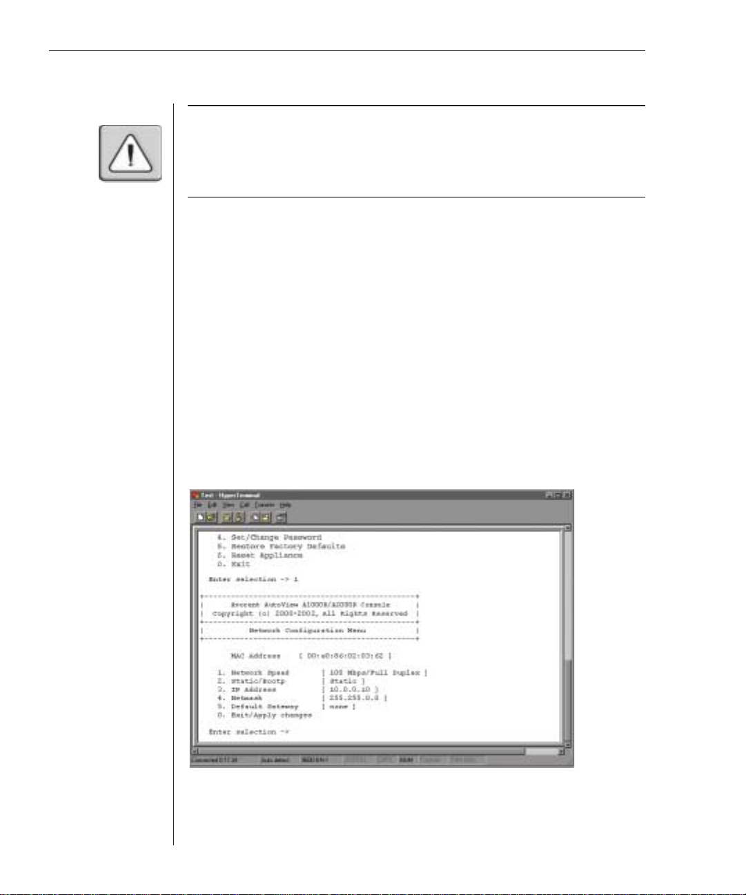
To confi gure the AutoView 1000R/2000R hardware:
1. You will see the Terminal Applications menu with six options. Select
option 1, Network Confi guration.
Figure 2.3: Network Configuration Menu

Chapter 2: Installation 13
2. Select option 1 from the Network Confi guration menu to set your network
speed. When possible, you should set your connection manually without
relying on the auto negotiate feature. Once you enter your selection, you
will be returned to the Network Confi guration menu.
3. Select option 2 and specify if you are using a static or BootP IP address.
Use a static IP address for ease of confi guration. If you are using a BootP
address, please confi gure your BootP server to provide an IP address to the
appliance, skip step 4 and continue to the next procedure.
4. Select options 3-5 from the Terminal Applications menu, in turn, to fi nish
confi guring your appliance for IP address, netmask and default gateway.
Once this is completed, type a Ø to return to the main menu.
To adjust the mouse acceleration:
Before a server can be connected to the AutoView 1000R/2000R, an adjustment
to mouse acceleration must be made. Use the default Microsoft
®
Windows
®
PS/2 mouse driver for all Microsoft Windows systems attached to the appliance.
For Microsoft Windows NT
®
(using default drivers):
1. From the desktop, select Start - Settings - Control Panel - Mouse. The
Mouse Properties dialog box will appear.
2. Click on the Motion tab.
3. Set the Pointer speed to Slow. You will need to set this for any Windows
NT user account that will be accessing the Windows NT system through
the appliance.
4. Set Acceleration to None for mouse sync.
For Microsoft Windows 2000/Windows XP (using default drivers):
1. From the desktop, select Start -Settings -Control Panel -Mouse. The Mouse
Properties dialog box will appear.
2. Click on the Motion tab.
3. Set the speed setting to the default of 50%.
4. If you are using Windows 2000, click the Mouse tab and set Acceleration to
None for mouse sync.
-or-
If you are using Windows XP, click the Pointer Options tab and check the
Enhance pointer precision checkbox.

14 AutoView 1000R/ AutoView 2000R Installer/User Guide
To connect an AVRIQ module to each server:
1. Locate the AVRIQ modules for your AutoView 1000R/2000R appliance.
2. Attach the appropriately color-coded ends to the keyboard (violet),
monitor (blue) and mouse (green) ports on the fi rst server you will be
connecting to the appliance.
3. Attach one end of the CAT 5 cabling that will run between your AVRIQ and
AutoView 1000R/2000R appliance to the RJ-45 connector on the
AVRIQ module.
4. Connect the other end of the CAT 5 cable to the desired ARI port on the
back of your AutoView 1000R/2000R appliance.
5. Repeat steps 2-4 for all servers you wish to attach.
NOTE: When connecting a Sun AVRIQ module, you must use a multi-sync monitor to
accommodate Sun computers that support both VGA and sync-on-green or composite sync.
See Appendix B for more information on the AVRIQ-SRL module.
To connect serial devices to the AutoView 1000R/2000R appliance:
1. Locate an AVRIQ-SRL module.
2. Attach the AVRIQ-SRL 9-pin serial connector to the serial port of the
device to be connected to your AutoView 1000R/2000R appliance.
3. Attach one end of the CAT 5 cable to the RJ-45 connector on the AVRIQ-
SRL module. Connect the other end of the CAT 5 cable to the desired ARI
port on the back of your AutoView 1000R/2000R appliance.
NOTE: The AVRIQ-SRL module is a DCE device and only supports VT100 terminal emulation.
4. Connect the power supply to the power connector on your AVRIQ-SRL.
The cable expander can be used to power up to four AVRIQ-SRL modules
from a single power supply.
5. Connect the AVRIQ-SRL power supply to an appropriate AC wall outlet.
Power up your serial device.
To connect an AVRIQ-PEM:
1. Locate the AVRIQ-PEM module.
2. Attach one end of a CAT 5 cable to the IN port on the AVRIQ-PEM module.
3. Connect the other end of the CAT 5 cable to the desired ARI port on the
back of your AutoView 1000R/2000R appliance.
4. Attach one end of another CAT 5 cable to one of the eight ports on the
AVRIQ-PEM module.
Chapter 2: Installation 15
5. Connect the other end of the CAT 5 cable to the appropriate AVRIQ
module for the server you want to connect to the appliance.
6. Repeat steps 4-5 for all servers you wish to attach. Up to eight servers may
be attached to the AutoView 1000R/2000R appliance through the
AVRIQ-PEM module.
NOTE: When a server is connected using an AVRIQ-PEM and is in use, other servers
connected through that AVRIQ-PEM cannot be accessed by other users.
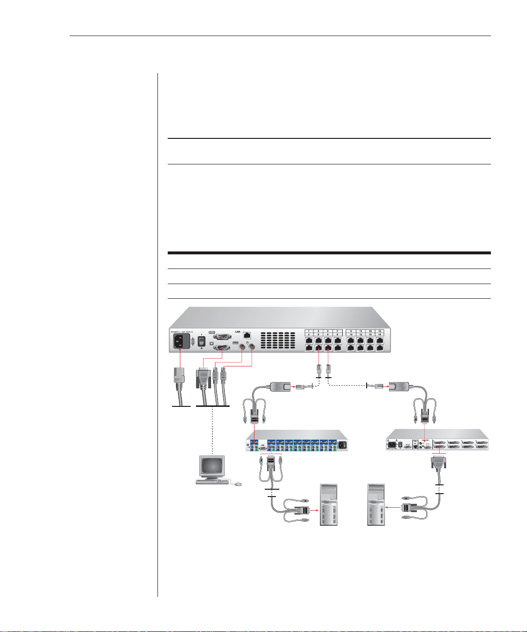
Adding a legacy KVM switch
You can add your legacy switches to the AutoView 1000R/2000R appliance for
better integration into your existing configuration. In a cascaded system, each
ARI port will accommodate up to 24 servers.
Legacy Switch Support
Legacy Product Model Numbers
OutLook
®
ES 140ES, 180ES, 280ES, 1160ES, 2160ES, 4160ES
AutoView AV200-4, AV200-8, AV400-4, AV400-8, AV416, AV424
Power
Cord
Local User
AVRIQ Module
PS/2, USB, Sun and
Serial are available
AVRIQ
Module
AutoView
200/400
Switch
KVM Connections
Outlook ES Switch
Server 1 Server 1
AutoView 1000R
Appliance
CAT 5 Cable
Figure 2.4: AutoView 1000R Configuration with a Legacy KVM Switch

16 AutoView 1000R/ AutoView 2000R Installer/User Guide
To add a legacy KVM switch:
1. Mount the legacy switch into your rack cabinet. Locate a length of CAT 5
cabling to connect your appliance to the AVRIQ for your legacy switch.
2. Attach one end of the CAT 5 cabling to the RJ-45 connector on the AVRIQ.
3. Connect the other end of the CAT 5 cable to a port on the back of your
AutoView 1000R/2000R.
4. Attach the keyboard, monitor and mouse connectors of the AVRIQ to a
user port on your legacy cascade switch.
5. Connect the servers to your Avocent cascade switch according to the
instructions included with the device.
6. Power cycle the legacy switch to enable the cascade code.
7. Repeat steps 2-5 for all cascade switches you want to attach to
your appliance.
To connect the network and turn on your AutoView 1000R/2000R:
1. Connect your network cable from the LAN port on the rear of the
AutoView 1000R/2000R appliance to your network.
2. The components in the AutoView 1000R/2000R system may be turned on
in any order. However, since the AVRIQ modules are powered by the
servers, turn on the servers fi rst and then turn on all attached systems for
the most effi cient startup.
Adding Servers
While you can configure the entire AutoView 1000R/2000R system through
either the OSCAR or AVWorks interfaces, we recommend first adding server
names to OSCAR at the local analog station prior to adding or discovering the
appliance in AVWorks at the remote digital station.
To add server names:
1. Launch OSCAR at the local analog station and input all server names. You
can also customize OSCAR as well as access the AutoView 1000R/2000R
from the local analog station. See Chapter 3 for detailed instructions on
OSCAR setup and confi guration.
2. After you install AVWorks on each remote digital station, launch AVWorks
and click Add New Appliance to add the new AutoView 1000R/2000R. The
server names you entered in OSCAR will now display in AVWorks for all
servers/AVRIQ modules that are powered up and online. AVRIQ modules
that are offl ine can be added later using the resync feature. See the
AVWorks Installer/User Guide that ships with your appliance.
 Loading...