


 Loading...
CYCLADES® ACS 5000
Installation/Administration/User Guide

FCC Warning Statement
The Cyclades ACS 5000 advanced console server has been tested and found to comply with the limits for Class A digital devices, pursuant to Part 15 of the FCC rules. These limits are designed to provide reasonable protection against harmful interference when the equipment is operated in a commercial environment.
This equipment generates, uses and can radiate radio frequency energy and, if not installed and used in accordance with the Installation and Service Manual, may cause harmful interference to radio communications.
Operation of this equipment in a residential area is likely to cause harmful interference in which case the user is required to correct the problem at his or her own expense.
Notice about FCC Compliance for All Cyclades ACS 5000 Advanced Console Server Models
To comply with FCC standards, the Cyclades ACS 5000 advanced console server requires the use of a shielded CAT 5 cable for the Ethernet interface. Notice that this cable is not supplied with the products and must be provided by the customer.
Canadian DOC Notice
The Cyclades ACS 5000 advanced console server does not exceed the Class A limits for radio noise emissions from digital apparatus set out in the Radio Interference Regulations of the Canadian Department of Communications.
L’Cyclades ACS 5000 advanced console server n’émete pas de bruits radioélectriques dépassant les limites applicables aux appareils numériques de la classe A prescrites dans le règlement sur le brouillage radioélectrique edicté par le Ministère des Communications du Canada.

Cyclades® ACS 5000
Installation/Administration/User Guide
Avocent, the Avocent logo, The Power of Being There, DSView and Cyclades are registered trademarks of Avocent Corporation or its affiliates in the U.S. and other countries. All other marks are the property of their respective owners.
© 2010 Avocent Corporation.
590-815-501B

Symbols Used
NOTE: The following symbolsmayappear within the documentation or on the appliance.
Instructions
This symbol is intended to alert the user to the presence of important operating and maintenance (servicing) instructions in the literature accompanying the appliance.
Dangerous Voltage
This symbol is intended to alert the user to the presence of uninsulated dangerous voltage within the product’s enclosure that may be of sufficient magnitude to constitute a risk of electric shock to persons.
Power On
This symbol indicates the principal on/off switch is in the on position.
Power Off
This symbol indicates the principal on/off switch is in the off position.
Protective Grounding Terminal
This symbol indicates a terminal which must be connected to earth ground prior to making any other connections to the equipment.
Functional Earthing Terminal
This symbol indicates a terminal which serves the purpose of establishing chassis ground equal potential.

v
TABLE OF CONTENTS
Introduction |
1 |
Overview |
1 |
Connectors on the Console Server |
1 |
Accessing the Console Server and Connected Devices |
2 |
Web Manager |
3 |
Prerequisites for Using the Web Manager |
3 |
Types of Users |
4 |
Security |
4 |
Authentication |
4 |
IPv6 |
6 |
Services not supporting IPv6 |
6 |
VPN |
6 |
Packet Filtering |
6 |
Structure of IP filtering |
6 |
Add rule and edit rule options |
7 |
SNMP |
9 |
Notifications, Alarms and Data Buffering |
9 |
Syslog servers |
9 |
Managing Users of Connected Devices |
10 |
Configuring access to connected devices |
10 |
Console Server and Power Management |
10 |
Configuring power management |
12 |
Options for managing power |
13 |
Hostname Discovery |
13 |
Installation |
15 |
Important Pre-installation Requirements |
15 |
Basic Installation Procedures |
15 |
Making an Ethernet connection |
16 |
Making a direct connection to configure the network parameters. |
17 |
Turning on the console server and the connected devices |
18 |

vi Cyclades® ACS 5000 Installation/Administration/User Guide
Performing basic network configuration using the wiz command |
18 |
Adding users and configuring ports using the web manager |
22 |
Other Methods of Accessing the Web Manager |
22 |
Connecting PDUs |
23 |
Web Manager for Regular Users |
25 |
Using the Web Manager |
25 |
Features of Regular User Forms |
25 |
Connect |
27 |
Connect to the console server |
27 |
Connect to serial ports |
27 |
Connection protocols for serial ports |
28 |
IPDU Power Management |
29 |
Outlets Manager |
29 |
Outlets Group Ctrl |
30 |
View IPDU info |
30 |
Security |
32 |
Web Manager for Administrators |
33 |
Common Features of Administrator Forms |
33 |
Logging Into the Web Manager |
35 |
Overview of Administrative Modes |
35 |
Wizard mode |
35 |
Expert mode |
36 |
Configuring the Console Server in Wizard Mode |
39 |
Step 1: Security Profile |
39 |
Step 2: Network Settings |
42 |
Step 3: Port Profile |
42 |
Step 4: Access |
44 |
Step 5: Data Buffering |
46 |
Step 6: System Log |
48 |
Applications |
51 |

Table of Contents |
vii |
Configuring the Console Server in Expert Mode |
51 |
Overview of menus and forms |
51 |
Applications Menu and Forms |
53 |
Connect |
53 |
IPDU Power Management |
54 |
Applications - IPDU Power Mgmt. - Outlets Group Ctrl |
57 |
Applications - IPDU Power Mgmt. - View IPDUs Info |
57 |
Applications - IPDU Power Mgmt. - Configuration |
59 |
Applications - IPDU Power Mgmt. - Software Upgrade |
61 |
Expert - Applications - PMD Configuration |
62 |
Applications - PMD Configuration- General |
62 |
Applications - PMD Configuration- Outlet Groups |
62 |
Applications - PMD Configuration - Users Management |
63 |
Expert - Applications - Terminal Profile Menu |
65 |
Network Menu and Forms |
67 |
Host Settings |
67 |
General host settings |
68 |
Disabling and enabling IPv4 or IPv6 protocols |
68 |
IPv4 settings |
69 |
IPv6 settings |
70 |
Syslog |
74 |
VPN Connections |
75 |
SNMP |
77 |
Firewall Configuration |
79 |
Host Table |
86 |
Static Routes |
86 |
Security Menu and Forms |
89 |
Users and Groups |
89 |
Active Ports Sessions |
91 |
Authentication |
92 |

viii Cyclades® ACS 5000 Installation/Administration/User Guide
Configuring authentication for console server logins |
93 |
Security Profiles |
98 |
Security certificates |
101 |
Ports Menu and Forms |
103 |
Physical Ports |
103 |
Virtual Ports |
124 |
Ports Status |
126 |
Ports Statistics |
126 |
Expert - Ports - Hostname Discovery |
127 |
Administration Menu and Forms |
129 |
System Information |
129 |
Notifications |
130 |
Time/Date |
135 |
Boot Configuration |
137 |
Backup Configuration |
139 |
Upgrade Firmware |
140 |
Reboot |
141 |
Online Help |
141 |
Appendix A: Technical Specifications |
143 |
Appendix B: Safety and environmental guidelines for rack-mounting the con- |
|
sole server |
145 |
Appendix C: Technical Support |
151 |

1
Introduction
1
Overview
Each model in the Cyclades® ACS 5000 advanced console server family is a 1U appliance serving as a single access point for accessing and administering servers and other devices, supporting both IPv4 and IPv6 protocols. The following figure shows the front of the console server.
Figure 1.1: Front of the Console Server
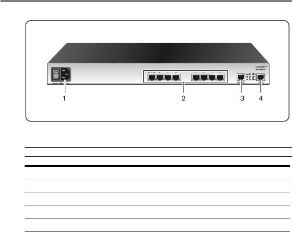
Connectors on the Console Server
The following figure depicts the connectors on the back of a typical ACS 5000 console server.
2 Cyclades® ACS 5000 Installation/Administration/User Guide
Figure 1.2: ACS 5000 Console Server Connectors
NOTE: The number of serialportsand power suppliesdependson the model.
Table 1.1: ACS 5000 Console Server Connectors
Number Description
1Power connection. Thismaybe single or dualpower. Dualpower requirestwo power cords.
2Serialport connectors.
3Ethernet port connectors.
4Console port connectors.
Accessing the Console Server and Connected Devices
You can access a console server and the connected servers or devices either locally or remotely using any of the following methods.
•Web manager through LAN/WAN IP networks.
•An external modem
•Using the web manager, you can log in and launch a console session such as Telnet or SSH to connect to the devices attached to the console server’s serial ports.
Chapter 1: Introduction 3
•Connecting a server running a terminal emulation program enables an administrator to log into the console server and either enter commands in the console server shell or use the Command Line Interface (CLI) tool.
NOTE: Onlyone root or admin user can have an active CLI or web manager session. Asecond root or admin user must abort the session or close the other user’ssession.
CAUTION: If there are cron jobsrunning through automated scripts, a root or admin user login can cause the
automated cron jobsto fail.
Web Manager
Console server administrators perform most tasks through the web manager either locally or from a remote location. The web manager runs in a browser and provides a real-time view of all equipment connected to the console server.
The administrator can use the web manager to configure users and ports. An authorized user can access connected devices through the web manager to troubleshoot, maintain, cycle power and reboot connected devices.
Access the web manager using one of the following ways:
•The IP Network.
•A dial-in connection with an optional external modem connected to one of the serial ports.
Prerequisites for Using the Web Manager
The following conditions must be met prior to accessing the web manager.
•Basic network parameters must be defined on the console server so the web manager can be launched over the network.
•The dynamically-assigned IP address of the console server must be known. This address is found in one of the following three ways:
•Make an inquiry to the DHCP server on the subnet that the console server resides, using the MAC address.
•Connect to the console server remotely using Telnet or SSH and use the ifconfig command.
•Connect directly to the console server and use the ifconfig command through a terminal emulator application.

4 Cyclades® ACS 5000 Installation/Administration/User Guide
•A web manager user account must be defined. The admin has an account by default, and can add regular-user accounts to grant access to the connected servers or devices using the web manager.
Types of Users
The console server supports the following user account types:
•The root user who can manage the console server and its connected devices. The root user performs the initial network configuration. Access privileges are full read/write and management.
•Users who are in an Admin group with administrative privileges. The admin user belongs to this group.
•Regular users who can access the connected devices through the serial ports they are authorized for. Regular users have limited access to the web manager features.
NOTE: It isstronglyrecommended that you change the default password avocentfor the root and admin users before configuring the console server.
Security
The console server includes a set of security profiles that consists of predefined parameters to control access to the console server and its serial ports. This feature provides more control over the services that are active at any one time. As an additional security measure, all serial ports are disabled by default, allowing the administrator to enable and assign individual ports to users.
NOTE: The Default securityprofile parametersare the same asthe Moderate profile.
Authentication
The console server supports a number of authentication methods to assist the administrator with user management. Authentication can be performed locally or with a remote server, such as RADIUS, TACACS+, LDAP or Kerberos. An authentication security fallback mechanism is also employed should the negotiation process with the authentication server fail. In such situations, the console server follows an alternate defined rule when the authentication server cannot authenticate the user.
The following table lists the supported authentication methods.

|
Chapter 1: Introduction 5 |
|
Table 1.2: Authentication Methods Supported |
||
Authentication Type |
Definition |
|
None |
No authentication. |
|
DSView |
Authentication isperformed with a DSView® 3 server. |
|
DSView/Local |
DSView management software authentication istried first, then Local. |
|
DSViewDownLocal |
Localauthentication isperformed onlyif the DSView 3 server isdown. |
|
Kerberos |
Authentication isperformed using a Kerberosserver. |
|
Kerberos/Local |
Kerberosauthentication istried first, switching to Localif unsuccessful. |
|
KerberosDownLocal |
Localauthentication isperformed onlywhen the Kerberosserver isdown. |
|
LDAP |
Authentication isperformed against an LDAPdatabase using an LDAPserver. |
|
LDAP/Local |
LDAPauthentication istried first, switching to Localif unsuccessful. |
|
LDAPDownLocal |
Localauthentication isperformed onlywhen the LDAPserver isdown. |
|
LDAPDownLocal/Radius |
Localauthentication isperformed onlywhen the LDAPserver isdown, switching to |
|
Radiusif unsuccessful. |
||
|
||
Local |
Authentication isperformed locally. For example using the /etc/passwd file. |
|
Local/Radius |
Authentication isperformed locallyfirst, switching to Radiusif unsuccessful. |
|
Local/TACACS+ |
Authentication isperformed locallyfirst, switching to TACACS+if unsuccessful. |
|
Local/NIS |
Authentication isperformed locallyfirst, switching to NISif unsuccessful. |
|
NIS |
NISauthentication isperformed. |
|
NIS/Local |
NISauthentication istried first, switching to Localif unsuccessful. |
|
NISDownLocal |
Localauthentication isperformed onlywhen the NISserver isdown. |
|
OTP |
Usesthe one time password (OTP) authentication method. |
|
OTP/Local |
Usesthe localpassword if the OTPpassword fails. |
|
Radius |
Authentication isperformed using a Radiusauthentication server. |
|
Radius/Local |
Radiusauthentication istried first, switching to Localif unsuccessful. |
|
RadiusDownLocal |
Localauthentication isperformed onlywhen the Radiusserver isdown. |
|
TACACS+ |
Authentication isperformed using a TACACS+authentication server. |
|
TACACS+/Local |
TACACS+authentication istried first, switching to Localif unsuccessful. |
|
TACACS+DownLocal |
Localauthentication istried onlywhen the TACACS+server isdown. |
|

6 Cyclades® ACS 5000 Installation/Administration/User Guide
IPv6
The console server is compliant with IPv4, IPv6 and dual stack protocols so that you can enable IPv4 only, IPv6 only or both protocols, with support for dial-up connections and primary network connections. You can configure the appliance to obtain its IPv6 network parameters from a DHCPv6 server, by static configuration (IP address, prefix length and default gateway) or stateless auto-configuration. You can add an appliance to the local network using either its IPv6 address or a DNS name.
Services not supporting IPv6
The following services do not support IPv6:
•NIS authentication
•NFS data logging
•Virtual ports
VPN
The console server administrator can set up VPN connections to establish an encrypted communication between the console server and a host on a remote network. The encryption creates a security tunnel for dedicated communications.
You can use the VPN features on the console server to create a secure connection between the console server and every machine on the subnet at the remote location or between the console server and a single remote host.
To set up a security gateway, install IPSec on any machine performing networking over IP, including routers, firewall machines, application servers and end-user machines.
The ESP and AH authentication protocols are supported. RSA Public Keys and Shared Secret are supported.
For detailed information and procedures to configure a VPN connection, see VPN Connections on page 75.
Packet Filtering
The administrator can configure the device to filter packets like a firewall. IP filtering is controlled by chains and rules.
Structure of IP filtering
The Firewall Configuration form in the web manager is structured on two levels:

Chapter 1: Introduction 7
•The view table of the Firewall Configuration form containing a list of chains.
•The chains which contain the rules controlling filtering.
Chain
A chain is a named profile that includes one or more rules defining either a set of characteristics to look for in a packet or what to do with any packet having all the defined characteristics.
The console server filter table contains a number of built-in chains, each referenced according to the packet type they handle. As defined in the rules for the default chains, all input and output packets and packets being forwarded are accepted.
Rule
Each chain can have one or more rules that define either the packet characteristics being filtered or what to do when the packet matches the rule.
Each filtered packet characteristic is compared against the rules. All defined characteristics must match. If no rules are found then the default action for that chain is applied.
Administrators can:
•Add a new chain and specify rules for that chain
•Add new rules to existing chains
•Edit a built-in chain or delete the built-in chain rules
Add rule and edit rule options
When you add or edit a rule, you can define any of the options described in the following table.
Table 1.3: Add Rule and Edit Rule Option Definitions
Filter Options
Source IPand Mask
Destination IPand Mask
Protocol
Description
With source IP, incoming packetsare filtered for the specified IPaddress. With destination IP, outgoing packetsare filtered.
If you fillin a source or destination mask, allpacketsare filtered for IPaddressesfrom the subnetworkin the specified netmask.
NOTE: For IPv6, onlyone field isavailable: <IPAddress>/<Prefix>.
Select protocoloptionsfor filtering from ALL, Numeric, TCP, UDP, ICMP(IPv4 only) and ICMPv6 (IPv6 only).
Input Interface |
The input interface (eth0) used bythe incoming packet. |
Output Interface |
The output interface (eth0) used bythe outgoing packet. |

8 Cyclades® ACS 5000 Installation/Administration/User Guide
Flag any of the above elements with Inverted to perform target action on packets not matching any criteria specified in that line. For example, if you select DROP as the target action, specify Inverted for a source IP address and do not specify any other criteria in the rule, any packets arriving from any other source IP address than the one specified are dropped.
Numeric protocol options
If you select Numeric as the protocol when specifying a rule, you need to specify the desired number.
TCP protocol options
If you select TCP as the protocol when specifying a rule, you can define the following options.
Table 1.4: TCP Protocol Option Definitions
Field/Menu option |
Definition |
Source or Destination Port
Specifya source or destination port number for filtering. Specifya range to filter TCPpacketsfor anyport number within the range.
Specifyanyof the flags: SYN (synchronize), ACK(acknowledge), FIN
TCPFlags
(finish), RST (reset), URG(urgent), PSH (push) and one of the Any, Set, or Unset conditionsto filter TCPpacketsfor the specified flag and selected condition.
UDP protocol options
Select UDP options by selecting UDP as the protocol when selecting a rule. Choose either the Source or Destination Port from the field, as defined above.
ICMP protocol options
When you select ICMP as a protocol when specifying a rule, you can select the ICMP options available on the display.
Target actions
The Target is the action to be performed on an IP packet that matches all the criteria specified in a rule.
NOTE: If the LOGand REJECT targetsare selected, additionaloptionsare available.
For detailed information on LOG target options, see LOG target on page 83.
For detailed information on REJECT target options, see REJECT target on page 84.

Chapter 1: Introduction 9
SNMP
The administrator can activate the Simple Network Management Protocol (SNMP) agent that resides on the console server so that the SNMP agent sends notifications about significant events or traps to an SNMP management application. The console server SNMP agent supports SNMP v1/v2 and v3.
For more information, see To configure SNMP: on page 78
Notifications, Alarms and Data Buffering
The administrator can set up logging, notifications and alarms to alert administrators of problems. System generated messages on the console server and the connected servers or devices can be sent to syslog servers for handling. The administrator can also configure data buffering to store data from communication on serial ports for monitoring.
Data from communication with serial-connected consoles can be stored locally in the console server’s flash memory or remotely either on an NFS server or a syslog server.
Syslog servers
Messages about the console server and connected servers or devices can be sent to central logging servers, called syslog servers. Console data from devices connected to serial ports can be stored in data buffer files on syslog servers. By default, logging and data buffering are not enabled.
Prerequisites for logging to syslog servers
Before configuring syslogging, ensure the syslog server is pre-configured with a public IP address and is accessible from the console server. The system administrator must obtain both the IP address of the syslog server from the syslog server’s administrator and the facility number for messages from the console server. Facility numbers are used on the syslog server for handling messages generated by multiple devices.
Facility numbers for syslog messages
Each syslog server has seven local facility numbers available for its administrator to assign to different devices or groups of devices, at different locations. The available facility numbers are local0 through local7.
Example of using facility numbers
The syslog system administrator sets up a server called syslogger to handle log messages from two console servers. One console server is located in São Paulo, Brazil and the other in Fremont, California. The syslog server’s administrator wishes to aggregate messages from the

10 Cyclades® ACS 5000 Installation/Administration/User Guide
São Paulo console server into the local1 facility and to aggregate messages from Fremont console server into the local2 facility.
On syslogger the system administrator has configured the system logging utility to write messages from the local1 facility to the /var/log/saopaulo-config file and the messages from the local2 facility to the /var/log/fremont-config file. If you were in Fremont and identifying the syslog server using the web manager, according to this example, you would select the facility number local2 from the Facility Number pull-down menu on the Syslog form.
Managing Users of Connected Devices
This section provides a list of tasks that a console server administrator can perform to enable access to connected devices.
Configuring access to connected devices
During hardware installation of the console server, the installer connects the servers, devices and any IPDUs to the serial ports. During software configuration, the console server administrator performs the common tasks listed in the following table.
Table 1.5: Common Administrator Tasks for Configuring Software
Task |
Where Documented |
To configure a serialport
To Configure a SerialPort Connection Protocolfor a Console Connection connection protocolfor a console connection: on page 107
To configure user accessto serial
To Configure User Accessto SerialPorts
ports: on page 112
Console Server and Power Management
Authorized users can turn on, turn off and reboot (turn off and turn on) devices that are plugged into one of the following types of power devices, which can be optionally connected to any of the serial ports:
•Avocent PM Power Distribution Units (PM PDUs) - With Avocent PM PDUs, up to 128 PDU outlets can be daisy-chained from a single serial port.
•Cyclades PM Intelligent Power Distribution Units (IPDUs) - With Cyclades PM IPDUs, up to 128 IPDU outlets can be daisy-chained from a single serial port.
•Avocent SPC power control devices.

Chapter 1: Introduction 11
•Server Technology Sentry™ family of Switched Cabinet Power Distribution Units (CDUs) and switched CDU Expansion Module (CW/CX) power devices.
•Server Technology Sentry Power Tower XL™ (PTXL) and Power Tower Expansion Module (PTXM) power devices.
•Server Technology Sentry Smart CDU (CS) and smart CDU Expansion Module power devices with version 6.0g or later.
NOTE: The term PDU isused to refer to anyof these typesof power devices.
The console server automatically recognizes and supports a Cyclades PM IPDU or Avocent SPC device when the serial port to which the power device is connected has been configured for power management.
Additional requirements for Server Technology IPDUs
For supported Server Technology IPDUs the following additional requirements apply:
•The console server must be managed by a DSView 3 server (DSView 3 software version 3.4.1 or above).
•The needed power device license must be present, and the power device must be added to the DSView 3 software.
The license is automatically downloaded from the DSView 3 server onto the console server. Configuration and management can then be performed either through the DSView 3 software or through the web manager.
Conventions used to identify outlets
Several formats (such as outlet names, outlet groups, IPDU IDs and port names) can be used to identify outlets during configuration, as described below:
•An administrator can configure optional names for each outlet to replace the default names assigned by the system. Outlet names must begin with a letter. Valid characters are letters, numbers, dash (-) and underscore (_). When an outlet name is configured, the name can be used in other power management configurations.
•An administrator can configure outlet groups. Once defined, outlet groups are specified with the dollar sign ($) prefix followed by the outlet group name: $outlet_groupname. For example, $Cyclades_IPDU specifies an outlets group called Cyclades_IPDU.
•An administrator can specify outlets in any of the following ways:
•With a name that was configured for the outlet
•With an outlet group name preceded by the $ suffix

12Cyclades® ACS 5000 Installation/Administration/User Guide
•With the IPDU ID assigned to the IPDU
•With the port number to which the IPDU is connected
The IPDU and port number are always followed by one or more outlet numbers in brackets: [outlets]. Commas between outlet numbers indicate multiple outlets. Hyphens indicate a range. For example, [1,5-8] specifies outlets 1, 5, 6, 7 and 8.
•IPDU ID - An IPDU ID is automatically assigned to each IPDU when the port to which it is connected is configured for power management. An administrator can optionally assign a name to each IPDU. Both automatically assigned and administrator-assigned names are referred to as IPDU IDs.
•Specify outlets with the IPDU ID in the following format: IPDU_ID[outlets]. For example, ilA[4,5] specifies outlets 4 and 5 on an IPDU whose ID is ilA.
•When devices are plugged into more than one IPDU, you can separate multiple IPDU entries with commas in the form IPDU_ID[outlets],IPDU_ID[outlets]. For example, i1A[1,5],i1B[2] specifies two outlets on IPDU i1A and one outlet on a daisy-chained IPDU whose IPDU ID is ilB.
•Port number - To specify outlets by the port number to which the IPDU is connected, use the suffix !ttyS followed by the port number followed by [outlets]. For example, !ttyS2[16] indicates outlet 16 on an IPDU that is connected to serial port 2.
You can specify outlets in a chain of IPDUs with the port ID two different ways:
•By the outlet sequence. For example, in !ttyS3[2,16], outlet number 2 is the second outlet on the first IPDU in a chain that is connected to port 3. If the first IPDU has 10 outlets, outlet number 16 would be the sixth outlet on the second IPDU.
•By IPDU sequence, identified with alphabetic characters. The first IPDU is A and the second is B and so forth. Precede the character with a hyphen. For example, !ttyS3-B[6] would also refer to the sixth outlet on the second IPDU in the chain connected to port 3.
Configuring power management
Administrators commonly perform power management through the web manager to assign power management permissions to users, configure IPMI devices and configure ports for power management.
Configuring ports for power management by authorized users
Administrators of connected devices who have power management permissions can do power management while connected by using a hotkey that brings up a power management screen.
Chapter 1: Introduction 13
For IPMI power management, the default hotkey is Ctrl+Shift+I. For IPDU power management, the default hotkey is Ctrl+p.
Options for managing power
Authorized users can perform power management through the console server by using forms in the web manager, from a power management screen while logged into a device or from the command line while logged into the console server.
An authorized user with administrative privileges can perform IPDU and IPMI power management. A regular user with permissions to the connected devices can perform IPDU power management.
Power management through the web manager
Users with power management permissions can perform power management through the web manager. The web manager menu includes two power management options, both discussed in Chapter 6.
Power management from the console server command line interface (CLI)
Console server administrators can use the ipmitool command to manage power on IPMI devices while logged into the console server with administrative rights. The ipmitool command is documented in the Cyclades ACS 5000 Command Reference Guide.
Hostname Discovery
An administrator can configure hostname discovery on the console server. When hostname discovery is enabled for a serial port, the console server attempts to discover the hostname of the server connected to the port. If the hostname of a server is successfully discovered, the hostname of the device connected to it is shown as the serial port alias.
If the server is later moved to another port, and the new port is also configured for hostname discovery, the hostname for the server is again discovered at the new serial port.
NOTE: If the console server isbeing managed through DSView 3 software, hostname discoverycan be configured through the DSView 3 software.
An administrator can also configure site-specific probe and answer strings. These strings are used to probe the target device that is connected to the selected serial port and extract the hostname from the answer that is received in response to the probe string. The result of each probe string is matched against all answer strings. If no match is found, the next probe string is sent until there are no more probe strings or a match occurs. The default strings have a broad range and work in most cases.
14 Cyclades® ACS 5000 Installation/Administration/User Guide
NOTE: Probe string configuration requiresknowledge of C-style escape sequences. Answer stringsrequire knowledge of POSIXextended regular expressions. Hostnameslonger than 31 charactersare truncated when the hostname isassigned to the serialport alias.

15
Installation
2
Important Pre-installation Requirements
Before installing and configuring the console server, ensure you have the following:
•Root Access on your local UNIX machine to use the serial ports.
•An appropriate terminal application for your operating system.
•IP address, DNS, Network Mask and Gateway addresses of your server or terminal, the console server and the machine to which the console server is connected.
•A internet browser that supports the console server web manager.
•Java 2 Runtime Environment (JRE) version 1.4.2 or later.
Basic Installation Procedures
Mounting the console server
You can mount the console server on a wall, rack or cabinet or place it on a desktop or other flat surface. Two brackets are supplied with six hex screws for attaching the brackets to the console server for mounting.

16 Cyclades® ACS 5000 Installation/Administration/User Guide
Figure 2.1: Placement of Mounting Brackets
To rack mount the console server:
1.Install the brackets on to the front or back edges of the console server using a screwdriver and the screws provided with the mounting kit.
2.Mount the console server in a secure position.
Making an Ethernet connection
Connect a CAT5 patch cable from the console server port labeled 10/100Base-T to an Ethernet hub or switch.
To connect devices to serial ports:
Using patch cables with RJ-45 connectors and DB-9 console adaptors assemble crossover cables to connect the console server serial ports to the device’s console port.

Chapter 2: Installation 17
Making a direct connection to configure the network parameters.
On your Microsoft® Windows workstation, ensure that a terminal emulation program is installed. On servers running a UNIX-based operating system such as Solaris or Linux, make sure that a compatible terminal emulator such as Kermit or Minicom is installed.
To connect to the console port:
You can use a CAT 5 straight-through cable with RJ-45 connectors and the appropriate adaptor provided in the product box to assemble a console cable. All adaptors have an RJ-45 connector on one end and either a DB25 or DB9 male or female connector on the other end.
1.Connect the RJ-45 end of the cable to the port labeled Console on the console server.
2.Connect the adaptor end of the cable to the console port of your server or device.
3.Open your terminal emulation program, start a connection session, select an available COM port and enter the following console parameters.
•Bits per second: 9600 bps
•Data bits: 8
•Parity: None
•Stop bit: 1
•Flow control: None
Console server serial port pin-out information
The following table provides the serial port pin-out information for the console server.
Table 2.1: ACS 5000 Console Server Serial Port Pin-out
Pin No. |
Signal Name |
Input/Output |
1 |
RTS |
OUT |
2 |
DTR |
OUT |
3 |
TxD |
OUT |
4 |
GND |
N/A |
5 |
CTS |
IN |
6 |
RxD |
IN |
7 |
DCD |
IN |
8 |
DSR |
IN |

18 Cyclades® ACS 5000 Installation/Administration/User Guide
Turning on the console server and the connected devices
Perform the following procedures in the order shown to avoid problems with components on connected devices.
To turn on the console server:
1.Make sure the console server’s power switch is off.
2.Plug in the power cable.
3.Turn the console server’s power switch(es) on.
NOTE: If your console server isequipped with dual-power supplies, make sure you turn both power switcheson. After system initialization, a beep sound maywarn if one of the power suppliesisoff.
To turn on connected devices:
Turn on the power switches of the connected devices only after you have completed the physical connection to the console server.
Performing basic network configuration using the wiz command
The following procedure assumes that a hardware connection is made between the console server’s console port and the COM port of a server.
To log into the console server through the console:
From your terminal emulation application, log into the console port as root.
ACS 5000 console server login: root
Password: avocent
WARNING: For securityreasons, it isrecommended that you change the default password for root (avocent) and admin (avocent) assoon aspossible. To change the default password of a root user, enter the passwd command at the prompt and enter a new password when prompted. To change the default password of an admin user, enter passwd admin at the prompt and enter a new password when prompted.
NOTE: The SecurityAdvisoryappearsthe first time the console server isaccessed or after a reset to factorydefault parameters. If you are upgrading the firmware on the console server, the previouslyconfigured security parametersare retained in the Flash memory.
To use the wiz command to configure network parameters:
1.Launch the configuration wizard by entering the wiz command.
[root@CAS root]# wiz
As shown below, the system displays the configuration wizard banner and begins running the wizard.

Chapter 2: Installation 19
***********************************************************
********* C O N F I G U R A T I O N W I Z A R D *********
***********************************************************
INSTRUCTIONS for using the Wizard:
You can:
1)Enter the appropriate information for your system and press ENTER or
2)Press ENTER if you are satisfied with the value within the brackets [ ] and want to go on to the next parameter or
3)Press ESC if you want to exit.
NOTE: For some parameters, if there is nothing within the brackets, it will continue to ask for a value.
In that case, you must enter a valid value or # if you do not wish to configure the value.
Press ENTER to continue...
2.At the prompt, press Enter to view the default settings.
3.At the prompt, enter n to change the defaults.
Set to defaults (y/n)[n]: n
4.Press Enter to accept the default hostname, or enter your own hostname and then press
Enter.
Hostname [CAS]: <hostname server name>
5.The IP version Configuration form is displayed. Select the IP version you wish to run and press Enter. Choices are IPv4 enabled (0), IPv6 enabled (1) or Dual Stack (2).
NOTE: Depending on which IPconfiguration you choose, the wizard willdirect you to the appropriate form.
To configure for IPv4 protocol:
1.If you have typed 0 or 2 for IP version configuration, the IPv4 Configuration form will appear and give you the choice to use DHCP to assign an IP address for your system. Default is Y.
2.Press Enter to keep DHCP enabled or type n to specify a static IP address for the console server. By default, the console server uses the IP address provided by the DHCP server. If your network does not use DHCP, the console server will default to 192.168.160.10.
Do you want to use DHCP to automatically assign an IP for your system? (y/n)[y] :

20 Cyclades® ACS 5000 Installation/Administration/User Guide
NOTE: If you choose to use DHCPand have selected IPv4 enabled (option 0), the IPv4 Current Configuration verification screen willbe displayed asshown below.
***************************************************************
*********** C O N F I G U R A T I O N W I Z A R D ***********
***************************************************************
Current configuration:
Hostname : Rogreto
Domain name : corp.company.com
Primary DNS Server : 172.26.29.4
Second DNS Server : #
IPv4 Configuration:
DHCP : enabled
IPv6 Configuration: Disable
Are all these parameters correct? (y/n) [n] :
3.Verify that the configuration is correct and press Enter. You will be prompted to activate the configuration settings.
4.If you typed n to change the default static IP address, enter a valid IPv4 system address.
System IP[192.168.160.10]: <ACS_5000_console_server_IP_address>
5.Press Enter. Enter the IP address for the gateway.
Gateway IP[eth0] : <gateway_IP_address>
6.Press Enter. Enter the netmask for the subnetwork.
Network Mask[#] : <netmask>
7.Press Enter.
NOTE: If you have selected IPv4 enabled and have set the staticIP, gatewayand netmaskaddresses, the IPv4 Current Configuration verification screen willbe displayed. Checkallparametersand pressEnter.You willbe prompted to activate the configuration settings.
To configure for IPv6 protocol:
1.If you entered option 1 or 2 for IP version configuration, the IPv6 Configuration Method form will be displayed.
2.Choices for IPv6 configuration are Stateless Only (0), Static (1) or DHCP (2). The default is Stateless Only. Type the number corresponding to your choice and press Enter. The choice you enter selects the method used to assign the IPv6 system address.

Chapter 2: Installation 21
•Stateless Only: The router will multicast the IPv6 prefix along with the console server’s MAC address, then listen for the other devices on the local network to allow the router to assign the IPv6 address.
•Static: You must manually assign a unique IPv6 address for the console server.
•DHCP: The router will request the IPv6 address from the DHCPv6 server.
3.The DHCPv6 options form is displayed. Choices are None (0), DNS (1), Domain (2) and DNS and Domain (3). Type the number corresponding to your choice and press Enter.
•From None (0): Enter your domain name.
•From Domain (1): Enter your domain name.
•From DNS (2): Follow the on-screen instructions.
•From DNS (3): The Current Configuration screen is displayed.
4.If None (0) or Domain (1), enter your domain name.
Domain name[corp.avocent.com] :
5.Enter the IPv4 or IPv6 address for the Primary DNS (domain name) server.
Primary DNS Server[172.26.29.4] : <DNS_server_IPv4_or_IPv6_address>
6.Press Enter. The Current Configurations screen appears. If correct, enter y after the prompts shown in the following screen example.
Are all these parameters correct? (y/n)[n]: y
Do you want to activate your configurations now? (y/n)[y]: y
Do you want to save your configuration to Flash? (y/n)[n]: y
7.To confirm the configuration, enter the ifconfig command.
8.After the initial configuration, proceed to the web manager to select a security profile as described in the following section.
NOTE: To use the web manager, obtain your console server’sIPaddress. The console server maybe set up with a staticIPaddressat your site. Bydefault, the console server usesthe IPaddressprovided bythe DHCPserver. If your networkdoesnot use DHCP, then the console server defaultsto 192.168.160.10.
Selecting a security profile using the web manager
After the initial configuration, connect to the web manager by entering the IP address of the console server in a supported browser.
NOTE: Once you log in to the web manager, a securityprofile must be selected to further configure the console server using the web manager. For thisreason your browser redirectsto Wizard - Step1: SecurityProfiles.

22 Cyclades® ACS 5000 Installation/Administration/User Guide
Selecting a security profile
Select a pre-defined security profile or define a custom profile for specific services. The profiles are:
•Secured - Disables all protocols except sshv2, HTTPS and SSH to serial ports.
•Moderate - Enables sshv1, sshv2, HTTP, HTTPS, Telnet, SSH and Raw connections to serial ports, ICMP and HTTP redirection to HTTPS.
•Open - Enables Telnet, sshv1, sshv2, HTTP, HTTPS, SNMP, RPC, ICMP, SSH and Raw connections to serial ports.
•Default - Sets the profile to the same configuration as Moderate profile.
•Custom - Allows custom configuration of individual protocols and services.
For detailed information on security profiles, see Security Profiles on page 98.
The administrator can perform the following tasks using the web manager.
•Administer the console server and its connected devices.
•Configure user and group permissions.
•Access the serial ports and the connected devices.
Adding users and configuring ports using the web manager
NOTE: From the factory, the console server isconfigured with allserialportsdisabled.
The administrator can add users, enable or disable the serial ports and select and assign specific users to individual ports. For more information on managing users and ports, see Security Menu and Forms on page 89 and Ports Menu and Forms on page 103
Other Methods of Accessing the Web Manager
You can access the web manager using either DHCP or the default IP address.
NOTE: Accessing the web manager using either DHCPor the default IPaddressrequiresadditionalsetup and configuration specificto your site’snetworkconfiguration.
To use a dynamic IP address to access the web manager:
This procedure assumes that DHCP is enabled and that you are able to obtain the dynamic IP address currently assigned to the console server.
1.Mount the console server.
2.Connect servers and other devices to be managed through the console server.
Loading...