


1515
Table of contents
 Loading...
AutoView
®
Installer/User Guide
For models: 1415, 1515 and 2015
Switch
USA Notification
Warning: Changes or modifications to this unit not expressly approved by the party responsible for compliance
could void the user’s authority to operate the equipment.
Note: This equipment has been tested and found to comply with the limits for a Class A digital device, pursuant to
Part 15 of the FCC Rules. These limits are designed to provide reasonable protection against harmful interference
when the equipment is operated in a commercial environment. This equipment generates, uses and can radiate
radio frequency energy and, if not installed and used in accordance with the instruction manual, may cause
harmful interference to radio communications. Operation of this equipment in a residential area is likely to cause
harmful interference in which case the user will be required to correct the interference at his own expense.
Canadian Notification
This digital apparatus does not exceed the Class A limits for radio noise emissions from digital apparatus set
out in the Radio Interference Regulations of the Canadian Department of Communications.
Le présent appareil numérique n’émet pas de bruits radioélectriques dépassant les limites applicables aux
appareils numériques de la classe A prescrites dans le Règlement sur le brouillage radioélectrique édicté par le
Ministère des Communications du Canada.
Japanese Approvals
Korean Approvals
Safety and EMC Approvals and Markings
UL, FCC Class A, cUL, ICES Class A, CE, GS, IRAM, GOST, VCCI Class A, MIC Class A, C-Tick

AutoView® Switch
1415/1515/2015
Instal ler/ User Gu ide
Avocent, the Avocent logo, The Power of Being There, AutoView,
OutLook and OSCAR are registered trademarks of Avocent Corporation
or its affiliates. All other marks are the property of their respective owners.
© 2007 Avocent Corporation. All rights reserved. 590-644-501C
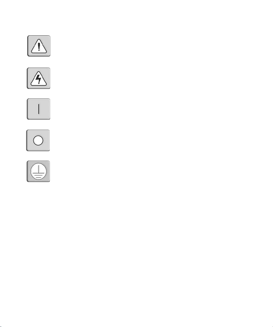
Instructions
This symbol is intended to alert the user to the presence of important operating and maintenance
(servicing) instructions in the literature accompanyi ng the appliance.
Dangerous Voltage
This symbol is intended to alert the user to the presenc e of uninsu la te d dang e rou s voltag e with in the
product’s enclosure that may be of sufficient magnitude to constitute a risk of electric shock to persons.
Power On
This symbol indicates the principal on/off switch is in the on position.
Power Off
This symbol indicates the principal on/off switch is in the off position.
Protective Grounding Terminal
This symbol indicates a terminal which must be connected to earth ground prior to making any other
connections to the eq uipment.


TABLE OF CONTENTS
Table of Contents
List of Figures ................................................................................................................ vii
List of Tables................................................................................................................... ix
Chapter 1: Product Overview.................... ....... ...... ....... ...................................... ....... ..... 1
Features and Benefits ........................................................................................................................1
Safety Precautions .............................................................................................................................4
Chapter 2: Installation ...................................... ...... ....... ...... ...... ....... ...... ......................... 7
Getting Started................................................ ...... .............................................................................7
Supplied with the AutoView switch.............................................................................................7
Rack Mounting Your AutoView Switch ..............................................................................................7
Installing the AutoView Switch..........................................................................................................8
Connecting Users.............................................................................................................................10
Cascading AutoView Switches.........................................................................................................10
Adding Legacy Switches ..................................................................................................................12
Setting Up Your AutoView Switching System..................................................................................15
v
Chapter 3: Basic Operations......................................................................................... 17
Controlling Your System at the Analog Ports..................................................................................17
Viewing and Selecting Ports and Servers........................................................................................17
Navigating the OSCAR Interface........................................... ..... .....................................................19
Configuring OSCAR Interface Menus.............................................................................................21
Assigning server names............................................................................................................22
Assigning device types..............................................................................................................24
Changing the display behavior.................................................................................................25
Setting the keyboard country code............................................................................................26
Selecting a language.................................................................................................................27
Controlling the status flag........................................................................................................ 28
Setting console security............................................................................................................29
Displaying Version Information ......................................................................................................33
Scanning Your System......................................................................................................................35
Running System Diagnostics............................................................................................................37
Broadcasting to Servers.............................................................. ...... ...... .........................................39

vi AutoView 1415/1515/2015 Switch Installer/User Guide
Changing Your Switch Mode...........................................................................................................41
Chapter 4: Advanced Operations ................................................................................. 43
Using Administrator Privileges.......................................................................................................43
Appendices..................................................................................................................... 47
Appendix A: Flash Upgrades...........................................................................................................47
Appendix B: Technical Specifications.............................................................................................50
Appendix C: Sun Advanced Key Emulation.....................................................................................52
Appendix D: Technical Support.......................................................................................................54

LIST OF FIGURES
List of Figures
Figure 1.1: Example of an AutoView Switch Configuration .............................................................4
Figure 2.1: AutoView Switch Horizontal Installation ......................................................................8
Figure 2.2: Basic AutoView Switch Configuration ..........................................................................9
Figure 2.3: AutoView 2015 Switch Configuration with a Cascaded Switch..................................12
Figure 2.4: AutoView 2015 Switch Configuration with Legacy KVM Switches ............................13
Figure 2.5: AutoView Switch Configuration with AutoView 1415/1515/2015 Switches.................14
Figure 3.1: Example of Configured Main Dialog Box....................................................................17
Figure 3.2: Setup Dialog Box (User)...............................................................................................22
Figure 3.3: Setup Dialog Box (Admin)............................................................................................22
Figure 3.4: Names Dialog Box........................................................................................................23
Figure 3.5: Name Modify Dialog Box.............................................................................................23
Figure 3.6: Devices Dialog Box......................................................................................................24
Figure 3.7: Device Modify Dialog Box ...........................................................................................25
Figure 3.8: Menu Dialog Box..........................................................................................................25
Figure 3.9: Keyboard Box...............................................................................................................27
Figure 3.10: Keyboard Warning Dialog Box..................................................................................27
Figure 3.11: Language Dialog Box.................................................................................................28
Figure 3.12: Flag Dialog Box.........................................................................................................29
Figure 3.13: Set Position Flag ........................................................................................................29
Figure 3.14: Security Dialog Box....................................................................................................30
Figure 3.15: Version Dialog Box ....................................................................................................33
Figure 3.16: Target Selection Dialog Box (Admin) ........................................................................34
Figure 3.17: Target Version Dialog Box........................................................................................34
Figure 3.18: Firmware Warning Dialog Box..................................................................................35
Figure 3.19: Scan Dialog Box.........................................................................................................36
Figure 3.20: Commands Dialog Box...............................................................................................37
Figure 3.21: Diagnostics Dialog Box..............................................................................................38
Figure 3.22: Diagnostics Warning Dialog Box...............................................................................39
Figure 3.23: Broadcast Dialog Box ................................................................................................40
Figure 3.24: Broadcast Enable Confirm/Deny Dialog Box ............................................................41
Figure 3.25: Switch Dialog Box......................................................................................................42
Figure 4.1: Security Menu...............................................................................................................43
vii

viii AutoView 1415/1515/2015 Switch Installer/User Guide
Figure 4.2: User Setup Menu (Administrator Only)........................................................................44
Figure 4.3: User Edit Menu (Administrator Only)..........................................................................45
Figure 4.4: User Access Menu (Administrator Only)......................................................................45
Figure A.1: AVRIQ Status Dialog Box............................................................................................48
Figure A.2: AVRIQ Upgrade Dialog Box........................................................................................49

LIST OF TABLES
List of Tables
Table 2.1: Legacy Switch Support................................... ........................................................ ........12
Table 3.1: OSCAR Interface Status Symbols................................................................................... 18
Table 3.2: OSCAR Interface Navigation Basics.............................................................................19
Table 3.3: Setup Features to Manage Routine Tasks for Your Servers...........................................21
Table 3.4: OSCAR Interface Status Flags......................................................................................28
Table 3.5: Diagnostic Test Details.................................................................................................38
Table B.1: Product Specifications..................................................................................................50
Table C.1: Sun Key Emulation ........................................................................................................52
Table C.2: PS/2-to-USB Keyboard Mappings.................................................................................53
ix

x AutoView 1415/1515/2015 Switch Installer/User Guide

CHAPTER
Product Overvi ew
1
Features and Benefits
The AutoView® 1415/1515/2015 swit ches inte gr ate Avocen t field-proven analog keyboard, video
and mouse (KVM) switching technology with advan ced cable management, flexible access for two
simultaneous users, USB support and a patented, easy-to-use interface. This AutoView series of
KVM switches conveniently supports all major server platfor ms and features powerfu l on-screen
management for easy system configuration and server selection. The AutoView 1415/1515/2015
switches also feature user peripheral ports for PS/2 and USB keyboards and mice.
NOTE: With the exception of USB capability, all references to AutoView 1415/1515/2015 switches are applicable
to AutoView 1400/1500/2000 switches respectively.
1
AVRIQ Intelligent Module
A benefit of the AutoView switch is the AVRIQ intelligent module. The AVRIQ module with
CAT 5 design dramatically reduces cable clutter, while providing optimal resolution and video
settings. The built-in memory of the AVRIQ module simplifies configuration by assigning and
retaining unique server names and Electronic ID (EID) numbers for each attached server. The
AVRIQ module is powered directly from the server and provides Keep Alive functionality even if
the AutoView switch is not powered.
Each AutoView 2015 switch has 16 Avocent Rack Interface (ARI) ports for connecting AVRIQ
modules. AutoView 1415 and 1515 switches p rovide eight ARI ports . Utilizing an AVRIQ module,
you can attach additional switches to expand your AutoView switching system. This flexibility
allows you to add capacity as your data center grows.
Multiplatform support
The AVRIQ modules available with the AutoView switch support PS/2, Sun™, USB and serial
server environments. Using the OSCAR
modules allows you to switch easily across platforms.
®
graphical user interface in conjunction with these

2 AutoView 1415/1515/2015 Switch Installer/User Guide
Two-User Share Mode
The AutoView 1415/1515/2015 switches feature a Share Mode function that allows two users to
gain access to a primary server. The user configurable time-out feature allows you to d etermine the
amount of time (up to 600 seconds) for the target to remain idle before the other user can take
control of the target.
OSCAR graphical user interface
AutoView switches use the OSCAR interface, which features intuitive menu s to conf igur e your
switching system and select servers. server s can be ident ified by un ique name, EID o r port number ,
allowing you to assign unique server names.
Security
The OSCAR interface allows you to protect your system with a screen saver password. After a
user-defined time, the screen saver mode engages and access is prohibited until the appropriate
password is entered to reactivate the system.
Operation modes
The OSCAR user interface provides co nve nient operation modes for easy system administr ation of
the AutoView switch. These modes (Broadcast, Scan, Switch and Share) allow you to manage your
switching activities. Chapter 3 explains these modes in detail.
Video
The AutoView switch provides optimal resolution for analog VGA, SVGA and XGA video.
Achieve resolutions of up to 1600 x 1200 @ 75Hz with a 100 foot (30 meter) cable.
NOTE: Resolutions above 1280 x 1024 may need to be manually set in the operating systems display settings.
Video resolution and distance is subject to cable quality and environmental factors.
Plug and Play
The AutoView switch also supports Display Data Channel (DDC) Plug and Play, which automates
configuration of the monitor and is compliant with the VESA DDC2B standard.
Flash upgradable
Upgrade your firmware at any time through a simple update utility to ensure that your AutoView
switching system is always running the most current version available. Both the AutoView switch
and the AVRIQ modules are Flash upgradable. See Appendix A for more information.
NOTE: Firmware available for the AutoView 1415/1515/2015 switch is also compatible with the AutoView 1400/
1500/2000 switch, but it is not compatible the AutoView 2020/2030 switch.

Chapter 1: Product Overview 3
Cascading expansion
Each AutoView switch supports up to 16 directly attached servers and can conveniently scale to
support more. You can expand your system using cascadable Avocent products such as other
®
AutoView or OutLook
switches. This extra “cascade” of units allows you to attach up to 256
servers in one system. See Chapter 2 for more information.
Local user accounts
The AutoView 1415/1515/2015 switches enable an administrator to configure up to four user
accounts for use with the switch. These user accounts allow the administrator to restrict what ports
a class of user can access, as well as the name of the user account and password. See Chapter 4 for
more information.
Integrated Access Cables
The AutoView 1415/1515/2015 switches also feature Integrated Access Cable (IAC) modules
designed to provide the same ease of use as the AVRIQ module. Available in three different
lengths, IAC modules are RJ-45 style cables that provide a reduced cost alternative to AVRIQ
modules. IAC modules support PS/2 and USB connectivity. Contact your Avocent representative
for more information.
NOTE: IAC modules are not upgradable.
4 AutoView 1415/1515/2015 Switch Installer/User Guide
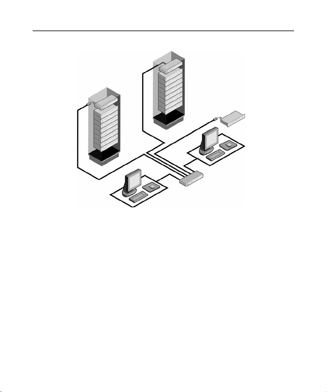
AutoView Switch
(Cascaded)
Legacy Switch
AVRIQ
or IAC
Module
Figure 1.1: Example of an AutoView Switch Configuration
(Cascaded)
Safety Precautions
Analog
Connection
Rack of Servers
Critical Server
AutoView Switch
(Main)
Analog
Connection
To avoid potential vid eo and/or keyboard pro blems when using Avocent products:
• Ιf the building has 3-phase A C pow er, ensure that the computers and monitors are on the sa me
phase. For best results, they should be on the same circuit.
• Use only Avocent-supplied cable to connect computers and KVM switches. Avocent
warranties do not apply to damage resulting from user-supplied cable.
To avoid potentially fatal shock hazard and possible damage to equipment, please observe the
following precautions:
• Do not use a 2-wire extension cord in any Avocent product configuration.
• Test AC outlets at the computer and monitor for proper polarity
and grounding.

Chapter 1: Product Overview 5
• Use only with grounded outlets at both the computer and monitor. When using a backup
Uninterruptible Power Supply (UPS), power the computer, the monitor and the AutoView
switch off the supply.
NOTE: The AC inlet is the main disconnect.
Rack mount safety considerations
• Elevated Ambient Temperature: If installed in a closed rack assembly, the operation
temperature of the rack environment may be greater than room ambient. Use care not to exceed
the rated maximum ambient temperature of the unit.
• Reduced Air Flow: Installation of the equipment in a rack should be such that the amount of
airflow required for safe operation of the equipment is not compromised.
• Mechanical Loading: Mounting of the equipment in the rack should be such that a hazardous
condition is not achieved due to uneven mechanical loading.
• Circuit Overloading: Consideration should be given to the connection of the equi pment to the
supply circuit and the effect that overloading of circuits might have on overcurrent protection
and supply wiring. Consider equipment nameplate ratings for maximum current.
• Reliable Earthing: Reliable earthing of rack mounted equipment should be maintained. Pay
particular attention to supply connections other than direct connections to the branch circuit
(for example, use of power strips).

6 AutoView 1415/1515/2015 Switch Installer/User Guide

CHAPTER
Installation
2
Getting Started
Before installing your AutoView switch, refer to the following list to ensure you have all items that
shipped with the AutoView switch, as well as other items necessary for proper installation.
Supplied with the AutoView switch
• Power cord
• One null modem serial cable
• Rack mounting kit
• AutoView 1415/1515/2015 Installer/User Guide
• AutoView 1415/1515/2015 Quick Installation Guide
7
Additional items needed
One IAC or AVRIQ modul e and CAT 5 cabling per attached server or switch
Rack Mounting Your AutoView Switch
Your AutoView switch may be rack moun ted usin g the brackets supplied in your rack mounting kit.
Before installing the switch and other components in the rack cabinet (if not already installed),
stabilize the rack in a permanent location. Install your equipment starting at the bottom of the rack
cabinet, then work to the top.
8 AutoView 1415/1515/2015 Switch Installer/User Guide
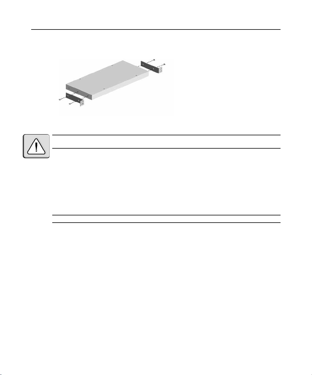
Figure 2.1: AutoView Switch Horizontal Installation
CAUTION: Rack Loading - Overloading or uneven loading of racks may result in shelf or rack failure, causing
damage to equipment and possible personal injury. Do not exceed your rack load rating.
To install the 1U switch mounting bracket:
1. Remove the first two screws on each side of the switch.
2. Line up the holes in the “long side” of the kit’s side brackets with the screw holes in the switch.
3. With a Phillips screwdriver, fasten the mounting brackets to the switch using two screws on
each side.
4. Attach four cage nuts or clip nuts to the rack mounting flange of the rack cabinet so that the nut
is positioned on the inside of the rack.
NOTE: Nuts are not included with the rack mount kit.
5. Mount the switch assembly to the rack cabinet by matching the holes in the “short side” of
each bracket to an appropriate set of matching holes on your rack cabinet.
6. Next, insert the combination hex head screws through the slots in the bracket and the holes in
the mounting rail, then into the cage nuts or clip nuts.
Installing the AutoView Switch
Plug the supplied power cord into the back of the appliance and then into an appropriate power
source. Figure 2.2 illustrates one possible configuration for your AutoView switch. See the fol lowing
detailed set of procedures to successfully install your appliance.
Chapter 2: Installation 9
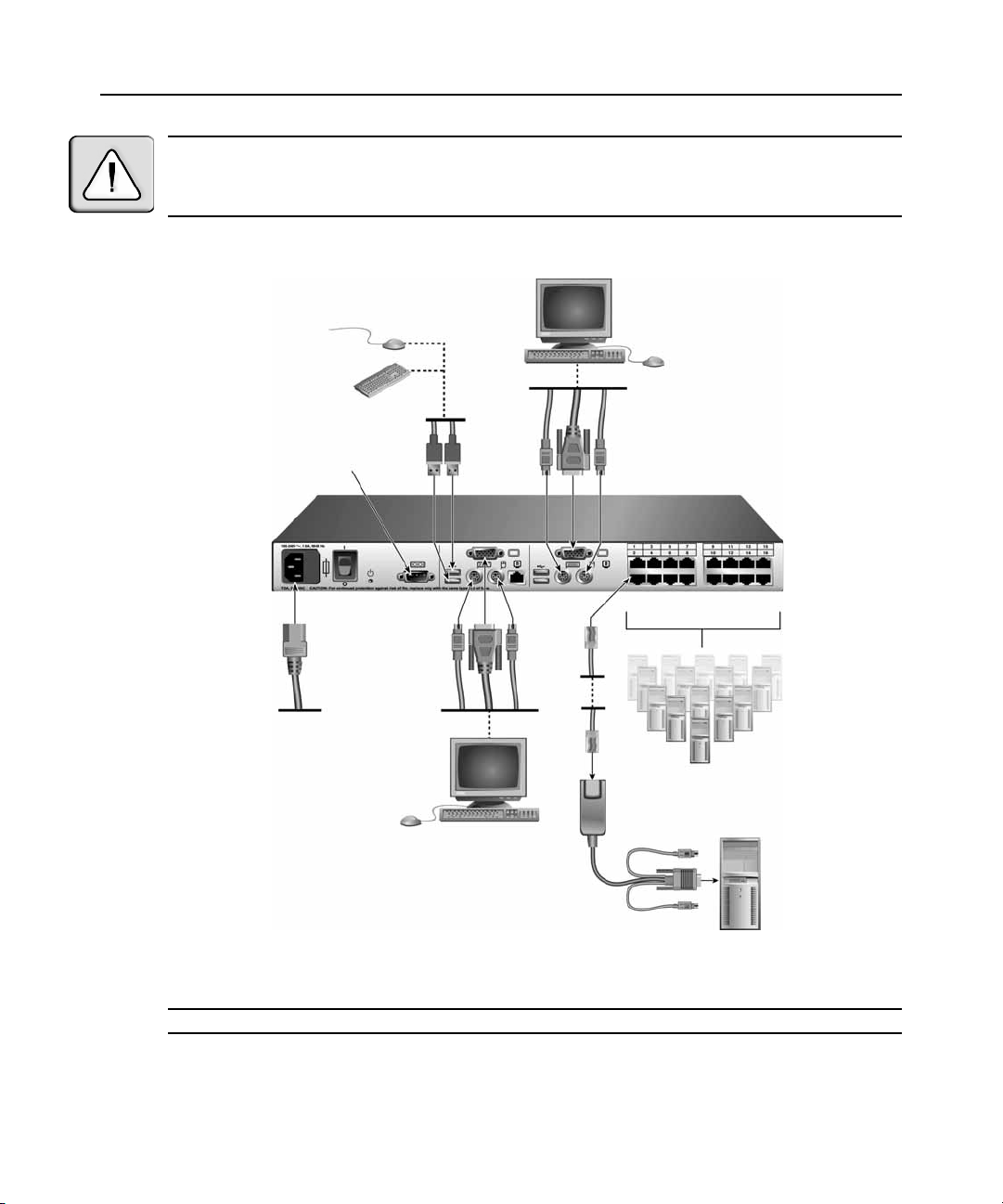
Analog User B
CAUTION: To r e d u c e th e r i s k o f e l e c t r i c s h o c k or damage t o y o u r eq u ipment -
- Do not disable the power cord grounding plug. The ground ing pl ug is an impo rta nt safety fe ature.
- Plug the power cord into a grounded (earthed) outle t that is easil y accessibl e at all t imes.
- Disconnect the power from the unit by unplugging th e power cord from either t he electri cal outlet or the unit.
Configuration Port
(for updating firmware)
AutoView Switch
Analog User A
IAC Module
AV RIQ Mod ule
Figure 2.2: Basic AutoView Switch Configuration
NOTE: Only the AutoView 1515 and the AutoView 2015 switches support two simultaneous users.
Servers 2-16
Server 1
Loading...