


DSR™
Installer/User Guide
For models: DSR800 DSR1010 DSR2010 DSR4010
INSTRUCTIONS
This symbol is intended to alert the user to the presence of important operating and maintenance (servicing) instructions in the literature accompanying the appliance.
DANGEROUS VOLTAGE
This symbol is intended to alert the user to the presence of uninsulated dangerous voltage within the product’s enclosure that may be of sufficient magnitude to constitute a risk of electric shock to persons.
POWER ON
This symbol indicates the principal on/off switch is in the on position.
POWER OFF
This symbol indicates the principal on/off switch is in the off position.
PROTECTIVE GROUNDING TERMINAL
This symbol indicates a terminal which must be connected to earth ground prior to making any other connections to the equipment.

 DSR™
DSR™
Installer/User Guide
Avocent, the Avocent logo, The Power of Being There, DSR, OutLook, AutoView, DSView and OSCAR are trademarks or registered trademarks of Avocent Corporation or its affiliates. All other marks are the property of their respective owners.
© 2003 Avocent Corporation. All rights reserved.
USA Notification
Warning: Changes or modifications to this unit not expressly approved by the party responsible for compliance could void the user's authority to operate the equipment.
Note: This equipment has been tested and found to comply with the limits for a Class A digital device, pursuant to Part 15 of the FCC Rules. These limits are designed to provide reasonable protection against harmful interference when the equipment is operated
in a commercial environment. This equipment generates, uses and can radiate radio frequency energy and, if not installed and used in accordance with the instruction manual, may cause harmful interference to radio communications. Operation of this equipment in a residential area is likely to cause harmful interference in which case the user will be required to correct the interference at his own expense.
Canadian Notification
This digital apparatus does not exceed the Class A limits for radio noise emissions from digital apparatus set out in the Radio Interference Regulations of the Canadian Department of Communications.
Le présent appareil numérique n’émet pas de bruits radioélectriques dépassant les limites applicables aux appareils numériques de la classe A prescrites dans le Règlement sur le brouillage radioélectrique édicté par le Ministère des Communications du Canada.
Japanese Approvals
Taiwanese
BSMI Certification
Korean Certification
Director General of Radio Research Laboratory, Ministry of Information and
Communication, Republic of Korea Certificate of Information and Communication
Equipment E-E011-02-2836 (A) and E-E011-03-2392 (A)
Agency Approvals
EN55022 Class A, EN55024, EN6200-3-2, EN6100-3-3, FCC15 Class A, VCCI Class A, IEC950, EN60950, UL 1950 third edition, CSA C22.2 No. 950

 Table of Contents
Chapter 1: Product Overview
Features and Benefits . . . . . . . . . . . . . . . . . . . . . . . . . 3
Safety Precautions . . . . . . . . . . . . . . . . . . . . . . . . . . . 6
Chapter 2: Installation
Getting Started . . . . . . . . . . . . . . . . . . . . . . . . . . . . . 11
Installing the DSR Appliance . . . . . . . . . . . . . . . . . 13
Chapter 3: Local Port Operation
Controlling Your System at the Local Port . . . . . . 23 Viewing and Selecting Ports and Servers . . . . . . . . 23 Navigating OSCAR . . . . . . . . . . . . . . . . . . . . . . . . . 25 Configuring OSCAR . . . . . . . . . . . . . . . . . . . . . . . . 27 Assigning Device Types . . . . . . . . . . . . . . . . . . . . . . 29 Changing the Display Behavior . . . . . . . . . . . . . . . 31 Controlling the Status Flag . . . . . . . . . . . . . . . . . . . 33 Broadcasting to Servers . . . . . . . . . . . . . . . . . . . . . . 34 Using Scan Mode . . . . . . . . . . . . . . . . . . . . . . . . . . . 36 Setting Console Security . . . . . . . . . . . . . . . . . . . . . 38 Setting the Keyboard Country Code . . . . . . . . . . . . 41 Managing Server Tasks Using OSCAR . . . . . . . . . 42 Viewing and Disconnecting User Connections . . . 44 Resetting Your PS/2 Keyboard and Mouse . . . . . . 45 Displaying Version Information . . . . . . . . . . . . . . . 46
Chapter 4: Terminal Operations
Accessing the Terminal Applications Menu . . . . . . 51
Appendices
Appendix A: FLASH Upgrades . . . . . . . . . . . . . . . . 57
Appendix B: Using DSRIQ-SRL Modules . . . . . . . 61
Appendix C: UTP Cabling . . . . . . . . . . . . . . . . . . . 66
Appendix D: Technical Specifications . . . . . . . . . . 68
Appendix E: Sun Advanced Key Emulation . . . . . 70
Appendix F: Technical Support . . . . . . . . . . . . . . . 72

1 Product Overview
Contents
Features and Benefits . . . . . . . . . . . . . . . . . . . . . . . . 3
Safety Precautions . . . . . . . . . . . . . . . . . . . . . . . . . . . 6


Chapter 1: Product Overview |
3 |
|
|
Chapter 1: Product Overview
Features and Benefits
Avocent’s DSR™ appliances combine analog and digital technology to provide flexible, centralized control of data center servers. This solution provides enterprise customers with a significant reduction of cable volume, secure remote access and flexible server management from anywhere at anytime.
The DSR appliance consists of a rack mountable keyboard, video and mouse (KVM) switch configurable for analog (local) or digital (remote) connectivity. Each DSR model has Avocent Rack Interface (ARI) ports for connecting servers and serial devices via DSRIQ modules. Video resolution of 1280 x 1024 is supported for remote users of the DSR system. Enhanced video quality of up to 1600 x 1280 is available for the local user via the keyboard, video and mouse ports.
The DSR works over standard LAN connections. Users can access servers (or serial devices) across a 100BaseT Ethernet connection or directly through a local port on the DSR for remote KVM access and administration, depending on the model selected. The IP-based DSR appliance gives you flexible server management control from anywhere in the world.
Reduce cable bulk
With server densities continually increasing, cable bulk remains one of the major concerns of every network administrator. The DSR significantly reduces KVM cable volume in the rack by utilizing the innovative DSRIQ module and single CAT 5 cabling. This allows a higher server density while providing greater airflow and cooling capacity.
The built-in memory of the DSRIQ simplifies configuration by assigning and retaining unique server names or Electronic ID (EID) numbers for each attached server. This integrated intelligence enhances security and prevents unauthorized access to a server through cable manipulation. The DSRIQ module is powered directly from the server and provides Keep Alive functionality whether or not the DSR appliance is powered up.
The DSRIQ-SRL (serial) module is a DCE device that provides the primary interface between a serial device and a DSR appliance. It provides VT100 terminal emulation, break suppression and port history in a convenient module. The DSRIQ-SRL is compatible with the ARI port of a DSR system.
These DSRIQ modules eliminate the need for extra rack space or additional cables. The connection between the DSR system and DSRIQ modules is via industry standard UTP cabling.

4 DSR Installer/User Guide
Access the DSR via network connection
No special software or drivers are required on the attached, or host, computers. Users access the DSR appliance and all attached systems via Ethernet from a PC running the DSViewTM application residing on the user PC. User PCs can be located anywhere a valid network connection exists. The DSR appliance can be configured on a separate network from your data network, allowing access to your servers even if your applications network is down.
Simple point and click access to any server
When a user activates DSView, it will display a listing of all computers and serial devices to which the user has permission to access. When a user selects a computer from the list, the video of the selected computer is displayed in a session window. Multiple servers can be accessed by one user. Each additional computer’s video will appear in a separate program window.
Create and manage user permissions with DES encrypted security
An administrator describes the configuration of computers attached to the DSR using an application called DSAdmin. Once the topology is described, the administrator then establishes which computers a user has permission to access. Usernames and passwords are derived from Windows NT®, eliminating the need for redundant user databases. Once the topology is established, the DSAuth software manages the system’s user permissioning. DSView polls the server running DSAuth for access permissions on power up and every time a switch is initiated for the most current permissions possible. A refresh is also available for immediate updates to a user’s access profile. In addition to the permissioning function, DSAuth also stores pertinent information about attached devices in a database. Room location, rack location and computer type can all be stored for quick reference.
Access serial devices
If an Avocent CPS810 or CPS1610 appliance is attached to the DSR unit, operators can gain access to serial devices through the DSView software. When a user connects to the network using DSView, a listing of all computers and serial devices to which the user has permission to access displays. Selecting a serial device will initiate a Telnet session.
|
|
|
|
Chapter 1: Product Overview |
5 |
|||
|
|
|
|
|
|
|
|
|
|
|
|
|
|
|
|
|
|
|
|
|
|
|
|
|
|
|
|
|
|
|
|
|
|
|
|
|
|
|
|
|
|
|
|
|
|
|
|
|
|
|
|
|
|
|
|
|
|
|
|
|
|
|
|
|
|
|
|
|
|
|
|
|
|
|
|
|
|
|
|
|
|
|
|
|
|
|
|
|
|
|
|
|
|
|
|
|
|
|
|
|
|
|
|
|
|
|
|
|
|
|
|
|
|
|
|
|
|
|
|
|
|
|
|
|
|
|
|
|
|
|
|
|
|
|
|
|
|
|
|
|
|
|
|
|
|
|
|
|
|
|
|
|
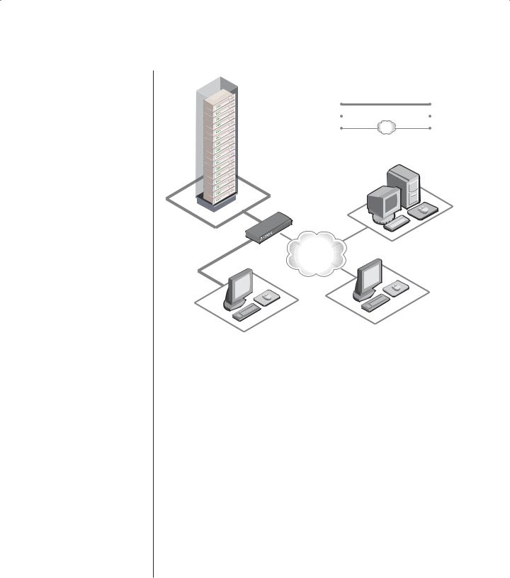
DSR2010
TCP/IP
Digital User Analog User (DSView) (OSCAR)
Figure 1.1: Example DSR Configuration
6 DSR Installer/User Guide
DSR 800
DSR 1010
100-240V |
, 1.0A, 50-60 Hz |
LAN |
1 |
3 |
5 |
7 |
9 |
11 |
13 |
15 |
|
|
|
2 |
4 |
6 |
8 |
10 |
12 |
14 |
16 |
DSR 2010
LAN |
1 |
3 |
5 |
7 |
9 |
11 |
13 |
15 |
|
2 |
4 |
6 |
8 |
10 |
12 |
14 |
16 |
DSR 4010 |
|
|
|
|
|
|
|
|
LAN |
1 |
3 |
5 |
7 |
9 |
11 |
13 |
15 |
|
2 |
4 |
6 |
8 |
10 |
12 |
14 |
16 |
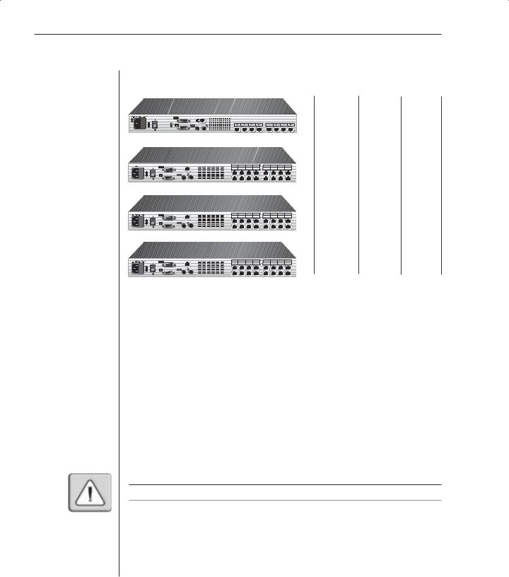
Figure 1.2: DSR Model Comparison
Safety Precautions
Number |
Digital |
Analog |
of |
sessions/ |
user |
servers |
output |
|
8 |
1 |
1 |
16 |
1 |
1 |
16 |
2 |
1 |
16 |
4 |
1 |
To avoid potential video and/or keyboard problems when using Avocent products:
•If the building has 3-phase AC power, ensure that the computer and monitor are on the same phase. For best results, they should be on the same circuit.
To avoid potentially fatal shock hazard and possible damage to equipment,
please observe the following precautions:
•Do not use a 2-wire power cord in any Avocent product configuration.
•Test AC outlets at the computer and monitor for proper polarity and grounding.
•Use only with grounded outlets at both the computer and monitor. When using a backup Uninterruptible Power Supply (UPS), power the computer, the monitor and the DSR appliance off the supply.
NOTE: The AC inlet is the main disconnect.

Chapter 1: Product Overview |
7 |
|
|
Rack mount safety considerations
•Elevated Ambient Temperature: If installed in a closed rack assembly, the operation temperature of the rack environment may be greater than room ambient. Use care not to exceed the rated maximum ambient temperature of the appliance.
•Reduced Air Flow: Installation of the equipment in a rack should be such that the amount of airflow required for safe operation of the equipment is not compromised.
•Mechanical Loading: Mounting of the equipment in the rack should be such that a hazardous condition is not achieved due to uneven mechanical loading.
•Circuit Overloading: Consideration should be given to the connection of the equipment to the supply circuit and the effect that overloading of
circuits might have on overcurrent protection and supply wiring. Consider equipment nameplate ratings for maximum current.
•Reliable Earthing: Reliable earthing of rack mounted equipment should be maintained. Pay particular attention to supply connections other than direct connections to the branch circuit (for example, use of power strips).

8 DSR Installer/User Guide

2 Installation
Contents
Getting Started . . . . . . . . . . . . . . . . . . . . . . . . . . . . . 11
Installing the DSR Appliance . . . . . . . . . . . . . . . . . 13


Chapter 2: Installation |
11 |
Chapter 2: Installation
The DSR system requires that the DSView, DSAdmin and DSAuth software be installed prior to use. DSView is the application that allows a user to view and control a server attached to the DSR system. DSAdmin is used to configure and maintain the system. DSAuth is a Windows NT or 2000 service used to prevent unauthorized access to the DSR system. More information on the DS Management Software suite can be found in your DSView Installer/
User Guide.
The DSR system uses Ethernet networking infrastructure and TCP/IP protocol to transmit keyboard, video and mouse information between operators and connected computers. Although 10BaseT Ethernet may be used, Avocent recommends a dedicated, switched 100BaseT network.
Getting Started
Before installing your DSR, refer to the following lists to ensure you have all items that shipped with the DSR as well as other items necessary for proper installation.
Supplied with the DSR
The following items are supplied with your DSR appliance:
•DSR appliance
•Local country power cord
•Rack mounting brackets
•Null modem cable
•DSR Installer/User Guide
•DSR Quick Install Guide
Additional items needed
The following are additional items needed to use your DSR appliance:
•One DSRIQ module per server or DSRIQ-SRL per serial device
•One CAT 5 patch cable per server or serial device (4-pair UTP, up to 10 meters)
•DS software

12 DSR Installer/User Guide
Verification of Ethernet/computer connections
DSR appliance
The front panel of the DSR features two LEDs describing the Ethernet connection. The top green LED is the Link indicator. It will illuminate when a valid connection to the network is established and blink when there is activity on the port. The lower amber LED, labeled 100M, will indicate that you are communicating at the 100 Mb rate.
Additionally, there are two LEDs above each port number on the front of your appliance: one green and one amber. The green LED will illuminate when the attached system is powered. The amber LED will illuminate when that port is selected by the DSView Client.
DSRIQ modules
PS/2, Sun and USB DSRIQ modules are available for attaching computers to your DSR appliance.
The DSRIQ-SRL serial module is used to connect serial devices to your DSR appliance and features two green LEDs: a POWER LED and a STATUS LED. The POWER LED indicates that the attached computer is powered. The
STATUS LED indicates that a valid UTP connection has been made to a DSR appliance. The DSRIQ-SRL prevents a serial break from the attached device if the module loses power. However, a user can generate a serial break with the attached device by pressing Alt-B in the Terminal Applications menu.
Setting up your network
The DSR system uses IP addresses to uniquely identify the server running DSAuth, the DSR appliances and the computers running DSView. The DSR supports both BootP (a subset of DHCP) and static IP addressing. Avocent recommends that IP addresses be reserved for each appliance and that they remain static while the DSR appliances are connected to the network. For additional information on how the DSR uses the TCP protocol, see Appendix B of the DSView Installer/User Guide. Figure 2.1 shows the DSR in a
network configuration.
|
|
|
|
|
Chapter 2: Installation |
13 |
||
|
|
|
|
|
|
|
|
|
|
|
|
|
|
|
|
|
|
|
|
|
|
|
|
|
|
|
|
|
|
|
|
|
|
|
|
|
|
|
|
|
|
|
|
|
|
|
|
|
|
|
|
|
|
|
|
|
|
|
|
|
|
|
|
|
|
|
|
|
|
|
|
|
|
|
|
|
|
|
|
|
|
|
|
|
|
|
|
|
|
|
|
|
|
|
|
|
|
|
|
|
|
|
|
|
|
|
|
|
|
|
|
|
|
|
|
|
|
|
|
|
|
|
|
|
|
|
|
|
|
|
|
|
|
|
|
|
|
|
|
|
|
|
|
|
|
|
|
|
|
|
|
|
DSR2010
Authentication Services (DSAdmin)
TCP/IP
Digital User Analog User (DSView) (OSCAR)
Figure 2.1: The DSR in a Network Configuration
Installing the DSR Appliance
The following diagram illustrates one possible configuration for your DSR appliance. Follow the detailed instructions to successfully install your DSR appliance.

14 DSR Installer/User Guide
Network
Configuration Port |
for updating |
fi rmware |
Digital User
DSR1010 Appliance
LAN
KVM |
Connections |
Power |
CAT 5 |
Cord |
Cable |
ARI Ports 1-16
Servers 2-16 |
Analog User
DSRIQ Module |
|
PS/2, USB, Sun and serial adaptors |
|
are available |
Server 1 |
Figure 2.2: Basic DSR Configuration
WARNING: To reduce the risk of electric shock or damage to your equipment-
-Do not disable the power cord grounding plug. The grounding plug is an important safety feature.
-Plug the power cord into a grounded (earthed) outlet that is easily accessible at all times.
-Disconnect the power from the appliance by unplugging the power cord from either the electrical outlet or the appliance.
Chapter 2: Installation |
15 |
|
|
To install the DSR hardware:
1.Remove the DSR appliance from the packing material.
2.Connect a terminal or PC running terminal emulation software (such as HyperTerminal®) to the Configuration port on the back panel of the DSR appliance using the supplied null modem cable. The terminal should be set to 9600 baud, 8 bits, 1 stop bit, no parity and no flow control.
3.Plug the supplied power cord into the back of the DSR appliance and then into an appropriate power source.
4.When the power is switched on, the Power indicator on the front of the appliance will blink for approximately 30 seconds while performing a selftest. Approximately 10 seconds after it stops blinking, press the Enter key to access the main menu.
NOTE: The DSR appliance may be rack mounted in a 1U confi guration. The DSR does not support a ØU confi guration.
To configure the DSR hardware:
1.You will see the Terminal Applications menu with six options. Select option 1, Network Configuration.
Figure 2.3: Network Configuration Menu
2.Select option 1 to set your network speed. When possible, you should set your connection manually without relying on the auto negotiate feature. Once you enter your selection, you will be returned to the Network Configuration menu.

16DSR Installer/User Guide
3.Select option 2 and specify if you are using a static or BootP IP address. Avocent recommends using a static IP address for ease of configuration. If you are using a BootP address, please configure your BootP server to provide an IP address to the DSR appliance, skip step 4 and continue to the next procedure.
4.Select options 3-5 from the Terminal Applications menu, in turn, to finish configuring your DSR for IP address, netmask and default gateway. Once this is completed, type a Ø to return to the main menu.
Adjusting mouse settings on target machines
NOTE: We highly recommend that all Windows systems attached to the DSR use the default
Windows PS/2 mouse driver.
Before a PC running Windows NT, 2000 or XP can be connected to the DSR for remote user control, an adjustment to the target mouse’s Motion tab must be made. Use the default Microsoft® Windows® PS/2 mouse driver for all Microsoft Windows systems attached to the appliance.
For Microsoft Windows NT (using default drivers):
1.From the Desktop, select Start - Settings - Control Panel - Mouse. The Mouse Properties dialog box will appear.
2.Click on the Motion tab.
3.Set the Pointer speed to Slow. This will also need to be done for any NT user account that will be accessing the NT system through the DSR.
4.Set Acceleration to None for mouse sync.
For Windows 2000 or Windows XP (using default drivers):
1.From the Desktop, select Start - Settings - Control Panel - Mouse. The Mouse Properties dialog box will appear.
2.Click on the Motion tab.
3.Set the speed setting to the default of 50%.
4.If you are using Windows 2000, click the Mouse tab and set Acceleration to None for mouse sync.
-or-
If you are using Windows XP, click the Pointer Options tab and check the
Enhance pointer precision checkbox.

Chapter 2: Installation |
17 |
|
|
To connect a DSRIQ module to each server:
1.Locate a DSRIQ for your DSR appliance.
2.Attach the appropriately color-coded ends to the keyboard (violet), monitor (blue) and mouse (green) ports on the first server you will be connecting to this DSR appliance.
3.Attach one end of the CAT 5 cabling that will run from your DSRIQ to the DSR appliance to the RJ-45 connector on the DSRIQ.
4.Connect the other end of the CAT 5 cable to the desired ARI port on the back of your DSR appliance.
5.Repeat this step for all servers you wish to attach.
NOTE: When connecting a Sun DSRIQ module, you must use a multi-sync monitor to accommodate Sun computers that support both VGA and sync-on-green or composite sync.
NOTE: Power down the DSR appliance before servicing. Always disconnect the power cord from the wall outlet.
To connect serial devices to the DSR appliance:
1.Locate a DSRIQ-SRL module.
2.Attach the DSRIQ-SRL 9-pin serial connector to the serial port of the device to be connected to your DSR appliance.
3.Attach one end of the CAT 5 cable to the RJ-45 connector on the DSRIQSRL module. Connect the other end of the CAT 5 cable to the desired ARI port on the back of your DSR appliance.
NOTE: The DSRIQ-SRL module is a DCE device and only supports VT100 terminal emulation.
4.Connect the power supply to the power connector on your DSRIQ-SRL. The cable expander can be used to power up to four DSRIQ-SRL modules from a single power supply.
5.Connect the DSRIQ-SRL power supply to an appropriate AC wall outlet. Power up your serial device. See Appendix B for more information on DSRIQ-SRL modules.
To connect the local port keyboard, monitor and mouse:
Attach your keyboard, monitor and mouse cable connectors to the appropriate
ports on the back of your DSR appliance.
NOTE: You must install both a keyboard and mouse on the local port or the keyboard will not initialize properly.

18 DSR Installer/User Guide
Adding a legacy KVM switch
You can add your legacy KVM switches to the DSR appliance for better integration into your existing configuration. In a cascaded system, each ARI port will accommodate up to 24 servers.
Legacy Switch Support
Legacy Product |
Model Numbers |
OutLook® ES |
140ES, 180ES, 280ES, 1160ES, 2160ES, 4160ES |
|
|
AutoView® |
AV200-4, AV200-8, AV400-4, AV400-8, AV416, AV424, AV2000-AM |
|
|
Power
Cord
KVM Connections |
CAT 5 Cable |
|
DSRIQ
Module


 Outlook ES Switch
DSR1010
Appliance
DSRIQ Module
PS/2, USB, Sun and serial modules are available
AutoView
200/400
Switch
Analog User |
|
Server 1 |
Server 1 |
Figure 2.4: DSR1010 Configuration with a Legacy KVM Switch
To add a legacy KVM switch:
1.Mount the legacy KVM switch into your rack cabinet. Locate a length of CAT 5 cabling to connect your DSR to the DSRIQ module for your legacy KVM switch.
2.Attach one end of the CAT 5 cabling to the RJ-45 connector on the DSRIQ module.
3.Connect the other end of the CAT 5 cable to a port on the back of your DSR appliance.
 Loading...