


DSR®Switch
Installer/User Guide
For models: DSR2035 DSR8035
Guide d’installation et d’utilisation
Pour les modèles DSR2035 et DSR8035

INSTRUCTIONS
This symbol is intended to alert the user to the presence of important operating and maintenance (servicing) instructions in the literature accompanying the appliance.
DANGEROUS VOLTAGE
This symbol is intended to alert the user to the presence of uninsulated dangerous voltage within the product’s enclosure that may be of sufficient magnitude to constitute a risk of electric shock to persons.
PROTECTIVE GROUNDING TERMINAL
This symbol indicates a terminal which must be connected to earth ground prior to making any other connections to the equipment.

DSR® Switch
Installer/User Guide
For models: DSR2035 and DSR8035
Avocent, the Avocent logo, The Power of Being There, DSR, DSView, Dambrackas Video Compression, AVWorks and OSCAR are registered trademarks of Avocent Corporation or its affiliates. All other marks are the property of their respective owners.
♥ 2005 Avocent Corporation. All rights reserved. 590-535-616A.

USA Notification
Warning: Changes or modifications to this unit not expressly approved by the party responsible for compliance could void the user’s authority to operate the equipment.
Note: This equipment has been tested and found to comply with the limits for a Class A digital device, pursuant to Part 15 of the FCC Rules. These limits are designed to provide reasonable protection against harmful interference when the equipment is operated in a commercial environment. This equipment generates, uses and can radiate radio frequency energy and, if not installed and used in accordance with the instruction manual, may cause harmful interference to radio communications. Operation of this equipment is a residential area is likely to cause harmful interference, in which case the user will be required to correct the interference at his/her own expense.
Canadian Notification
This Class A digital apparatus complies with Canadian ICES-003.
Cet appareil numérique de la classe A est conforme à la norme NMB-003 du Canada.
Japanese Notification
Korean Notification
Safety and EMC Approvals and Markings
UL, FCC, cUL, ICES-003, CE, GS, VCCI, MIC, C-Tick, GOST

iii
TABLE OF CONTENTS
List of Figures ................................................................................................................ |
vii |
List of Tables ................................................................................................................... |
ix |
Chapter 1: Product Overview.......................................................................................... |
1 |
Features and Benefits ........................................................................................................................ |
1 |
Reduce cable bulk ....................................................................................................................... |
2 |
Control of virtual media-capable appliances ............................................................................. |
2 |
Access the DSR2035/8035 switch via network connection......................................................... |
2 |
Simple access to any target device ............................................................................................. |
2 |
Safety Precautions ............................................................................................................................. |
4 |
Rack Mount Safety Considerations.................................................................................................... |
4 |
Chapter 2: Installation ..................................................................................................... |
5 |
DSR Switch Connectivity ................................................................................................................... |
5 |
Installation overview .................................................................................................................. |
5 |
Setting up your network.............................................................................................................. |
8 |
Getting started ............................................................................................................................ |
8 |
Connecting the DSR2035/8035 switch hardware....................................................................... |
9 |
Verifying the Connections................................................................................................................ |
11 |
DSR2035/8035 switch............................................................................................................... |
11 |
DSRIQ modules ........................................................................................................................ |
11 |
Configuring the Web Server and DSView 3 Software ..................................................................... |
11 |
Setting up the built-in web server ............................................................................................. |
11 |
Setting up the DSView 3 software............................................................................................. |
12 |
Adjusting Mouse Settings on Target Devices .................................................................................. |
12 |
Microsoft Windows ................................................................................................................... |
12 |
LINUX....................................................................................................................................... |
14 |
UNIX ......................................................................................................................................... |
17 |
Novell NetWare......................................................................................................................... |
19 |
Apple Mac OS........................................................................................................................... |
20 |

iv |
DSR2035/8035 Switch Installer/User Guide |
|
|
Chapter 3: Local Port Operation................................................................................... |
21 |
|
Controlling Your System at the Local Port...................................................................................... |
21 |
|
Viewing and selecting ports and servers .................................................................................. |
21 |
|
Viewing the status of your DSR2035/8035 switching system ................................................... |
23 |
|
Navigating the OSCAR Interface..................................................................................................... |
25 |
|
Configuring OSCAR Interface Menus ............................................................................................. |
26 |
|
Setting virtual media options .................................................................................................... |
41 |
|
Managing server tasks using the OSCAR interface.................................................................. |
42 |
|
Chapter 4: Web Server Operations............................................................................... |
49 |
|
Overview of the DSR2035/8035 Web Server ................................................................................... |
49 |
|
Viewing and Selecting Ports and Servers ........................................................................................ |
49 |
|
About the DSR Explorer Window .................................................................................................... |
50 |
|
Using the side navigation bar................................................................................................... |
51 |
|
Using the top option bar ........................................................................................................... |
52 |
|
Launching a KVM session ........................................................................................................ |
53 |
|
Managing a DSR web server device......................................................................................... |
53 |
|
Managing local accounts.......................................................................................................... |
54 |
|
Managing device properties ..................................................................................................... |
55 |
|
Power Controlling Target Devices .................................................................................................. |
56 |
|
Chapter 5: The Video Viewer......................................................................................... |
59 |
|
About the Video Viewer Window ..................................................................................................... |
59 |
|
Video Viewer Minimum Requirements ............................................................................................ |
59 |
|
Launching a KVM Session............................................................................................................... |
60 |
|
Video Viewer Window Features ...................................................................................................... |
61 |
|
Changing the toolbar................................................................................................................ |
63 |
|
Setting the window size............................................................................................................. |
63 |
|
Adjusting the view..................................................................................................................... |
64 |
|
Adjusting color depth................................................................................................................ |
65 |
|
Additional video adjustment ..................................................................................................... |
66 |
|
Adjusting mouse options ........................................................................................................... |
69 |
|
Using Keyboard Pass-through......................................................................................................... |
71 |
|
Using Macros................................................................................................................................... |
72 |
|
Saving the View................................................................................................................................ |
72 |
|
Closing a Video Viewer Window Session ........................................................................................ |
73 |

Table of Contents |
v |
Chapter 6: Terminal Operations ................................................................................... |
75 |
The Console Menu ........................................................................................................................... |
75 |
Network Configuration .................................................................................................................... |
75 |
Other Console Main Menu Options................................................................................................. |
77 |
Security configuration .............................................................................................................. |
77 |
Local user accounts .................................................................................................................. |
78 |
Console password..................................................................................................................... |
79 |
Reset certificates....................................................................................................................... |
79 |
Security mode............................................................................................................................ |
79 |
Firmware management............................................................................................................. |
79 |
Enable debug messages ............................................................................................................ |
79 |
Restore factory defaults ............................................................................................................ |
80 |
Reset appliance......................................................................................................................... |
80 |
Exit............................................................................................................................................ |
80 |
Appendices..................................................................................................................... |
81 |
Appendix A: FLASH Upgrades........................................................................................................ |
81 |
Appendix B: Using DSView Software Over a Modem Connection ................................................. |
83 |
Appendix C: Using DSRIQ-SRL Modules ....................................................................................... |
84 |
Appendix D: UTP Cabling............................................................................................................... |
88 |
Appendix E: Technical Specifications ............................................................................................. |
90 |
Appendix F: Sun Advanced Key Emulation..................................................................................... |
92 |
Appendix G: Technical Support....................................................................................................... |
94 |
Index................................................................................................................................ |
95 |

vi DSR2035/8035 Switch Installer/User Guide

vii
LIST OF FIGURES
Figure 1.1: Example DSR2035/8035 Switch Configuration ............................................................. |
3 |
Figure 2.1: Basic DSR2035/8035 Switch Configuration (Showing the DSR8035 Model)................ |
7 |
Figure 3.1: OSCAR Interface Main Dialog Box.............................................................................. |
22 |
Figure 3.2: OSCAR Interface Setup Dialog Box ............................................................................. |
27 |
Figure 3.3: OSCAR Interface Names Dialog Box ........................................................................... |
28 |
Figure 3.4: OSCAR Interface Name Modify Dialog Box ................................................................ |
29 |
Figure 3.5: OSCAR Interface Devices Dialog Box ......................................................................... |
30 |
Figure 3.6: OSCAR Interface Device Modify Dialog Box............................................................... |
31 |
Figure 3.7: OSCAR Interface Menu Dialog Box............................................................................. |
32 |
Figure 3.8: OSCAR Interface Flag Dialog Box .............................................................................. |
33 |
Figure 3.9: Position Flag ................................................................................................................ |
34 |
Figure 3.10: OSCAR Interface Broadcast Dialog Box.................................................................... |
35 |
Figure 3.11: OSCAR Interface Scan Dialog Box ............................................................................ |
36 |
Figure 3.12: OSCAR Interface Commands Dialog Box .................................................................. |
37 |
Figure 3.13: OSCAR Interface Screen Saver Dialog Box ............................................................... |
38 |
Figure 3.14: OSCAR Interface Keyboard Dialog Box .................................................................... |
40 |
Figure 3.15: OSCAR Interface Virtual Media Dialog Box ............................................................. |
42 |
Figure 3.16: OSCAR Interface Commands Dialog Box .................................................................. |
43 |
Figure 3.17: OSCAR Interface User Status Dialog Box ................................................................. |
44 |
Figure 3.18: OSCAR Interface Disconnect Dialog Box .................................................................. |
44 |
Figure 3.19: OSCAR Interface Version Dialog Box........................................................................ |
46 |
Figure 3.20: DSRIQ Selection Dialog Box...................................................................................... |
46 |
Figure 3.21: DSRIQ Version Dialog Box........................................................................................ |
47 |
Figure 4.1: Avocent DSR Explorer Window.................................................................................... |
50 |
Figure 4.2: Side Navigation Bar...................................................................................................... |
51 |
Figure 5.1: Video Viewer Window (Normal Window Mode) .......................................................... |
61 |
Figure 5.2: Manual Video Adjust Dialog Box................................................................................. |
66 |
Figure 5.3: Video Viewer Window with Local and Remote Cursors Displayed ............................. |
69 |
Figure 6.1: Console Main Menu...................................................................................................... |
76 |
Figure 6.2: Network Configuration Menu....................................................................................... |
76 |

viii DSR2035/8035 Switch Installer/User Guide
ix
LIST OF TABLES
Table 3.1: Main Dialog Box Functions ........................................................................................... |
22 |
Table 3.2: OSCAR Interface Status Symbols ................................................................................... |
23 |
Table 3.3: OSCAR Interface Navigation Basics.............................................................................. |
25 |
Table 3.4: Setup Features to Configure the OSCAR Interface........................................................ |
26 |
Table 3.5: OSCAR Interface Status Flags ....................................................................................... |
33 |
Table 3.6: Virtual Media Options.................................................................................................... |
41 |
Table 3.7: Commands to Manage Routine Tasks for Your Target Devices .................................... |
42 |
Table 4.1: DSR Explorer Window Area Descriptions ..................................................................... |
51 |
Table 4.2: Viewing Appliance Information...................................................................................... |
55 |
Table 5.1: Video Viewer Window Description ................................................................................ |
62 |
Table 5.2: Manual Video Adjust Dialog Box Descriptions ............................................................. |
67 |
Table C.1: DSRIQ-SRL Module Pinouts ......................................................................................... |
87 |
Table D.1: UTP Wiring Standards .................................................................................................. |
88 |
Table E.1: DSR2035/8035 Switch Product Specifications .............................................................. |
90 |
Table F.1: Sun Key Emulation......................................................................................................... |
92 |
Table F.2: PS/2-to-USB Keyboard Mappings ................................................................................. |
93 |

x DSR2035/8035 Switch Installer/User Guide

1
CHAPTER
Product Overview
1
Features and Benefits
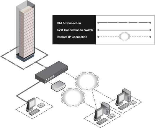
Avocent DSR® switches combine analog and digital technology to provide flexible, centralized control of data center servers and virtual media, and to facilitate the OA&M (operations, activation and maintenance) of remote branch offices where trained operators may be unavailable. They provide enterprise customers with a significant reduction of cable volume, secure remote access and flexible server management from anywhere at anytime.
Each DSR2035/8035 switch model consists of the following features:
•a rack mountable keyboard, video and mouse (KVM) switch, configurable for analog (local) or digital (remote) connectivity
•video resolutions supported up to 1280 x 1024 for remote users
•enhanced video quality of up to 1600 x 1200 available to local users via the video port
•user peripheral ports for PS/2 and USB keyboards and mice
•2 SPC ports that can be used to connect to an SPC power control device
•virtual media capability accessed through any one of five USB ports
•accessibility to target devices across one of two 1000BaseT LAN ports that are used to establish dual Ethernet connections with the second Gigabit Ethernet port (LAN2) serving as a backup during a failover event on LAN1
•accessibility to target devices directly through a local port
•a MODEM port that supports V.34, V.90 or V.92-compatible modems that may be used to access the switch when an Ethernet connection is not available
The IP-based DSR2035/8035 switches give you flexible target device management control from anywhere in the world.

2 DSR2035/8035 Switch Installer/User Guide
Reduce cable bulk
With server densities continually increasing, cable bulk remains a major concern for network administrators.The DSR2035/8035 switches significantly reduce KVM cable volume in the rack by utilizing the innovative DSRIQ module and single, industry-standard Unshielded Twisted Pair (UTP) CAT 5 cabling. This allows a higher server density while providing greater airflow and cooling capacity.
The DSRIQ module is powered directly from the target device and provides Keep Alive functionality when the DSR2035/8035 switch is not powered.
The DSRIQ-SRL (serial) module is a DCE device that provides the primary interface between a serial device and a DSR2035/8035 switch. It provides VT100 terminal emulation, break suppression and port history in a compact, convenient module.
Control of virtual media-capable appliances
The DSR2035/8035 switch allows you to view, move or copy data located on virtual media to and from any server. This feature allows you to manage remote systems more efficiently by allowing operating system installation, operating system recovery, hard drive recovery or duplication, BIOS updating and server backup.
Virtual media can be connected directly to the DSR2035/8035 switch using one of five USB ports located on the switch. In addition, virtual media may be connected to any remote workstation that is running DSView® management software and is connected to the DSR2035/8035 switch using an Ethernet connection.
NOTE: To open a virtual media session with a server, the server must first be connected to the switch using a virtual media capable DSRIQ module (USB2 or USB2L).
Access the DSR2035/8035 switch via network connection
No special software or drivers are required on the attached, or client, computers.
NOTE: The client connects to the server housing the DSView management software using an Internet browser. For modem access, you must install DSR Remote Operations software included on the DSView software CDROM (see the DSView Installer/User Guide for more information).
Users access the DSR2035/8035 switch and all attached systems via Ethernet or using a V.34, V.90 or V.92 modem from a client computer, such as a PC. Clients can be located anywhere a valid network connection exists.
Simple access to any target device
When a user accesses the DSView Server software, a listing of all target devices to which the user has permission to view and manage is displayed. When a user selects a target device from the list, the video of the selected target device is displayed in a Video Viewer window.
Chapter 1: Product Overview |
3 |
|
|
DSR2035/8035 Switch
Ethernet |
DSView |
|
|
Modem |
Software Server |
|
|
Telephone |
|
Network |
|
Analog User
(OSCAR® Graphical
Digital User
User Interface)
(Computer with Internet browser)
Figure 1.1: Example DSR2035/8035 Switch Configuration

4 DSR2035/8035 Switch Installer/User Guide
Safety Precautions
To avoid potential video and/or keyboard problems when using Avocent products:
•If the building has 3-phase AC power, ensure that the computer and monitor are on the same phase. For best results, they should be on the same circuit.
To avoid potentially fatal shock hazard and possible damage to equipment, please observe the following precautions:
•Do not use a 2-wire power cord in any Avocent product configuration.
•Test AC outlets at the target device and monitor for proper polarity and grounding.
•Use only with grounded outlets at both the target device and monitor. When using a backup Uninterruptible Power Supply (UPS), power the target device, the monitor and the DSR2035/8035 switch from the UPS.
NOTE: The AC inlet is the main power disconnect.
Rack Mount Safety Considerations
•Elevated Ambient Temperature: If installed in a closed rack assembly, the operating temperature of the rack environment may be greater than room ambient. Use care not to exceed the rated maximum ambient temperature of the switch.
•Reduced Air Flow: Installation of the equipment in a rack should be such that the amount of airflow required for safe operation of the equipment is not compromised.
•Mechanical Loading: Mounting of the equipment in the rack should be such that a hazardous condition is not achieved due to uneven mechanical loading.
•Circuit Overloading: Consideration should be given to the connection of the equipment to the supply circuit and the effect that overloading of circuits might have on overcurrent protection and supply wiring. Consider equipment nameplate ratings for maximum current.
•Reliable Earthing: Reliable earthing of rack mounted equipment should be maintained. Pay particular attention to supply connections other than direct connections to the branch circuit (for example, use of power strips).

5
CHAPTER
Installation
2
DSR Switch Connectivity
The DSR2035/8035 switching system requires connectivity to a server running the DSView 3 software. DSView 3 software allows a user to view and control target devices (one at a time) attached to the DSR2035/8035 switching system. For more information on the DSView 3 software, see the DSView Installer/User Guide.
The DSR2035/8035 switching system transmits keyboard, video and mouse (KVM) information between operators and target devices attached to the DSR2035/8035 switch over a network using either an Ethernet connection or a modem connection.
The DSR2035/8035 switch uses TCP/IP for communication over Ethernet. Although 10BaseT Ethernet may be used, Avocent recommends a dedicated, switched 100BaseT network, or even a 1000BaseT network.
The DSR2035/8035 switch uses the Point-to-Point Protocol (PPP) for communication over a V.34, V.90 or V.92 modem.You can perform KVM switching tasks by using one of the following:
•the web server built into the switch
•DSView 3 software
Installation overview
If you plan to use the DSView 3 software for access, please refer to the DSView 3 Quick Install Guide that is included with the DSView 3 software package.
The general procedure for setting up and installing the a DSR switch that has an on-board web server is as follows:
Setting up your network for the on-board web server
DSR switching systems that have the on-board web server use IP addresses to uniquely identify the switch and the target devices. The DSR switch supports both Dynamic Host Configuration Protocol (DHCP) and static IP addressing. Avocent recommends that IP addresses be reserved for each switch and that they remain static while the DSR switches are connected to the network. For additional information on setting up the DSR switch using the DSView 3 software, and for

6 DSR2035/8035 Switch Installer/User Guide
information on how the DSR switch uses TCP/IP, see the DSView Installer/User Guide or DSView 3 Software Online Help.
Installing the DSR switch
The general procedure for setting up and installing the DSR2035/8035 switch is as follows:
•Unpack the DSR2035/8035 switch and verify that all components are present and in good condition. See the Getting started section in this chapter.
•Make all hardware connections between the power source, DSR2035/8035 switch, target devices, optional SPC device, the Ethernet and the optional modem connection. See the
Connecting the DSR2035/8035 switch hardware section.
•Turn on the power and verify that all connections are working. See the Verifying the Connections section.
•If you are configuring the DSR2035/8035 switch using the console menu interface, do that at this point. See Chapter 4 for more information.
•Use the DSView Server software to configure the DSR2035/8035 switch. See the DSView Installer/User Guide for detailed instructions.
•Make the appropriate mouse setting adjustments. See the Adjusting Mouse Settings on Target Devices section.
Figure 2.1 on page 7 illustrates a basic configuration for the DSR2035/8035 switch, using the DSR8035 switch as a model for the example.

Chapter 2: Installation |
7 |
|
|
Modem |
Analog User |
Telephone |
|
Network |
|
Network |
External |
Digital User |
Virtual Media |
|
DSR8035 Switch
|
SPC Port |
|
Power |
Connection |
|
|
|
|
Cord |
|
|
|
|
Ports |
|
|
1-32 |
|
SPC Port |
|
|
Connections |
|
|
SPC |
|
|
Power Control |
Local USB |
|
Device |
|
|
Connections |
|
SPC |
|
|
|
|
|
Power Control |
Servers 1-32 |
|
Device |
|
|
* To open a virtual media session with a server, the server must first be connected to the switch using a virtual media-capable DSRIQ module (USB2 or USB2L).
DSRIQ Modules PS/2, USB*, Sun and serial adaptors are available.
Figure 2.1: Basic DSR2035/8035 Switch Configuration (Showing the DSR8035 Model)

8 DSR2035/8035 Switch Installer/User Guide
Setting up your network
The DSR2035/8035 switching system uses IP addresses to uniquely identify the switch and the target devices. The DSR2035/8035 switch supports both Dynamic Host Configuration Protocol (DHCP) and static IP addressing. Avocent recommends that IP addresses be reserved for each switch and that they remain static while the DSR2035/8035 switches are connected to the network. For additional information on setting up the DSR2035/8035 switch using the DSView Server software, and for information on how the DSR2035/8035 switch uses TCP/IP, see the DSView Installer/User Guide.
Getting started
Before installing your DSR2035/8035 switch, refer to the following lists to ensure you have all items that shipped with the DSR2035/8035 switch, as well as other items necessary for proper installation.
Supplied with the DSR2035/8035 switch
•Local country power cord
•Rack mounting brackets
•Rack Mounting Bracket Quick Installation Guide
•Two ribbon cables with RJ-45 connectors at each end
•One RJ-45 to DB-9 (male) adaptor for the modem connection
•One RJ-45 to DB-9 (female) adaptor for the SETUP port
•DSR Installer/User Guide (this manual)
•DSR Quick Installation Guide
Additional items needed
•One DSRIQ module per target server or DSRIQ-SRL module per serial device
•One CAT 5 patch cable per DSRIQ module (4-pair UTP, up to 10 meters)
•One CAT 5 patch cable for network connectivity (4-pair UTP, up to 10 meters)
•One USB2 or USB2L DSRIQ module per target server for virtual media sessions
•DSView 3 software
•(Optional) V.34, V.90 or V.92-compatible modem and cables
•(Optional) SPC power control device
Chapter 2: Installation |
9 |
|
|
Connecting the DSR2035/8035 switch hardware
NOTE: The DSR2035/8035 switch may be rack mounted in a 1U configuration. The DSR2035/8035 switch does not support a 0U configuration.
To connect and power up your DSR2035/8035 switch:
1.Power down the target device(s) that will be part of your DSR2035/8035 switching system. Locate the power cord that came with the DSR2035/8035 switch. Plug one end into the power socket on the rear of the DSR2035/8035 switch. Plug the other end into an appropriate AC wall outlet.
WARNING: To reduce the risk of electric shock or damage to your equipment:
-Do not disable the power cord grounding plug. The grounding plug is an important safety feature.
-Plug the power cord into a grounded (earthed) outlet that is easily accessible at all times.
-Disconnect the power from the switch by unplugging the power cord from either the electrical outlet or the appliance.
2.Plug your VGA monitor and either PS/2 or USB keyboard and mouse cables into the appropriately labeled DSR2035/8035 switch ports. You must install both a keyboard and mouse on the local ports or the keyboard will not initialize properly.
3.Choose an available numbered port on the rear of your DSR2035/8035 switch. Plug one end of a CAT 5 patch cable (4-pair, up to 10 meters) into the selected port and plug the other end into the RJ-45 connector of a DSRIQ module.
4.Plug the DSRIQ module into the appropriate ports on the back of the target server. Repeat this procedure for all servers that are to be connected to the DSR2035/8035 switch. See To connect a DSRIQ module to a server and To connect a DSRIQ module to a serial device for
more information.
5.Plug a CAT 5 patch cable from your Ethernet network into the LAN1 port on the back of your DSR2035/8035 switch. Network users will access the DSR2035/8035 switch through this port.
6.(Optional) The DSR2035/8035 switch can also be accessed using a ITU V.92, V.90 or V.34compatible modem. Plug one end of one of the the included ribbon cables into the MODEM port on the back of your DSR2035/8035 switch. Plug the other end into the RJ-45 to DB-9 adaptor (male), and plug the adaptor into the connector on the modem.
NOTE: Using a modem connection instead of a LAN connection will limit the performance capability of your DSR2035/8035 switch.
7.(Optional) Plug one end of the cable supplied with the SPC power control device into the SPC 1 port on the DSR2035/8035 switch and plug the other end into an SPC device. Plug the power cords from the target servers into the SPC device power outlets. Plug the SPC device into a grounded AC wall outlet. Repeat this step for the SPC 2 port if fail-over capability
is desired.

10DSR2035/8035 Switch Installer/User Guide
8.(Optional) To configure the DSR2035/8035 switch using the console menu interface, use the
second supplied ribbon cable and RJ-45 to DB9 (female) adaptor to connect a terminal or a PC that is running terminal emulation software (such as HyperTerminal®) to the SETUP port on the back panel of the DSR2035/8035 switch. The terminal should be set to 9600 bits per second (bps), 8 bits, 1 stop bit, no parity and no flow control. Otherwise, proceed to the
next step.
9.Power up each target device and then power up the DSR2035/8035 switch. After approximately one minute, the switch completes initialization and displays the OSCAR® graphical user interface Free tag on the local port monitor.
10.Use the DSView 3 software to configure the switch. See the DSView Installer/User Guide for detailed instructions.
To connect a DSRIQ module to a server:
1.Attach the color-coded connectors of a DSRIQ module to the corresponding keyboard, monitor and mouse ports on the server you will be connecting to this DSR2035/8035 switch.
2.Attach one end of the CAT 5 patch cable to the RJ-45 connector on the DSRIQ module. Connect the other end of the CAT 5 patch cable to the desired port on the back of your DSR2035/8035 switch.
Repeat this procedure for all servers you wish to attach.
NOTE: When connecting a Sun DSRIQ module, you must use a multi-sync monitor in the local port to accommodate Sun computers that support both VGA and sync-on-green or composite sync.
To connect local virtual media:
Connect the virtual media to any one of the five USB ports on the DSR2035/8035 switch.
NOTE: For all virtual media sessions, you must use a USB2 or USB2L DSRIQ module.
To connect a DSRIQ module to a serial device:
1.Attach the DSRIQ-SRL module 9-pin serial connector to the serial port of the device to be connected to your DSR2035/8035 switch.
2.Attach one end of the CAT 5 patch cable to the RJ-45 connector on the DSRIQ-SRL module. Connect the other end of the CAT 5 patch cable to the desired port on the back of your DSR2035/8035 switch.
NOTE: The DSRIQ-SRL module is a DCE device and only supports VT100 terminal emulation.
3.Connect the power supply to the power connector on your DSRIQ-SRL module. The cable expander can be used to power up to four DSRIQ-SRL modules from a single power supply.
4.Connect the DSRIQ-SRL module power supply to a grounded AC wall outlet. Power up your serial device. See Appendix C on page 84 for more information on DSRIQ-SRL modules.

Chapter 2: Installation |
11 |
|
|
Verifying the Connections
DSR2035/8035 switch
The front panel of the DSR2035/8035 switch features LEDs indicating the Ethernet connection for both LAN1 and LAN2:
•The green LED, labeled Link, illuminates when a valid connection to the network is established at a rate of 1000 Mbps and blinks when there is activity on the port.
•The amber LED illuminates when you are communicating at a rate of 100 Mbps when using an Ethernet connection.
•If neither LED is illuminated, connection speed is at a rate of 10 Mbps.
Additionally, the front panel of the DSR2035/8035 switch has LEDs for each port that indicate the target device status:
•A green LED illuminates when the attached target device has power.
•An amber LED illuminates when that port is selected.
•The LEDs blink during a firmware upgrade.
DSRIQ modules
NOTE: PS/2, Sun, USB, USB2 and USB2L DSRIQ modules are available for attaching servers to your DSR switch. If your DSR switch supports virtual media, connect virtual media devices to a workstation using USB2 and USB2L DSRIQ modules.
Use the DSRIQ-SRL serial module to connect serial devices to the DSR2035/8035 switch. The DSRIQ-SRL module features two green LEDs: a POWER LED and a STATUS LED.
•The POWER LED indicates that the attached DSRIQ-SRL module is powered.
•The STATUS LED indicates that a valid selection has been made to a DSR2035/8035 switch.
The DSRIQ-SRL module prevents a serial break from the attached device if the module loses power. However, a user can generate a serial break with the attached device by pressing Alt-B after accessing the Terminal Applications menu.
Configuring the Web Server and DSView 3 Software
Because the DSR2035/8035 switch has an on-board web server, you must configure the web server and install the DSView 3 software.
Setting up the built-in web server
You can access the DSR2035/8035 switch via an embedded web server that handles most day-to- day switching tasks. Before using the web server to access the switch, first specify an IP address

12 DSR2035/8035 Switch Installer/User Guide
through the SETUP port on the back panel of the switch. See Chapter 6 for detailed instructions on how to use the SETUP port and web server to configure the switch.
Setting up the DSView 3 software
See the DSView Installer/User Guide that ships with your software, or refer to the DSView 3 Software Online Help.
Adjusting Mouse Settings on Target Devices
Before a computer connected to the DSR2035/8035 switch can be used for remote user control, you must set the target mouse speed and turn off acceleration. For machines running Microsoft® Windows® (Windows NT®, 2000, XP, Server 2003), use the default PS/2 mouse driver.
To ensure that the local mouse movement and remote cursor display remain in sync, mouse acceleration needs to be set to “none” for all user accounts accessing a remote system using a KVM switch. Mouse acceleration should also be set to “none” on every remote system. Special cursors should not be used and cursor visibility options, such as pointer trails, Ctrl key cursor location animations, cursor shadowing and cursor hiding should also be turned off.
This section explains the steps for setting mouse movement and cursor features for use with Avocent hardware products and DSView® management software with the following operating systems:
•Microsoft® Windows® NT 4.0, 2000, XP, Server 2003 and IntelliPoint® drivers
•LINUX® Red Hat® (pre-8.0, 8.0 and later, and Enterprise) and SUSE®
•UNIX® Sun Solaris® (versions 9 and 10)
•Novell® NetWare®
•Apple® MAC® OS 10.3 and later
NOTE: If you are not able to disable mouse acceleration from within your operating system, or if you do not desire to adjust the settings of all your servers, newer versions of the DSView 3 software include the Tools - Single Cursor Mode command available in the Video Viewer window. This command places the Video Viewer window into an “invisible mouse” mode which allows you to manually toggle control between the mouse pointer on the target system being viewed and the mouse pointer on the client running DSView 3 software.
Microsoft Windows
NOTE: Avocent highly recommends that all Microsoft® Windows systems attached to the DS1800 digital switch, DSR switches, CCM console management appliances and SwitchView IP remote access devices use the default Windows PS/2 mouse driver.
To adjust the mouse speed and pointer settings for NT 4.0 (using default drivers):
1.From the Desktop taskbar, select Start - Settings - Control Panel to open the Control Panel.
2.In the Control Panel, double-click the Mouse icon to open the Mouse Properties dialog box.
Chapter 2: Installation |
13 |
|
|
3.Click the Motion tab.
4.Set the Pointer speed slider to Slow (the leftmost tick mark).
5.Make sure the Snap to default checkbox is cleared.
6.Click OK to save your settings and to close the Mouse Properties dialog box.
7.Resynchronize the mouse in the software remote session window for the Avocent management software you are using:
•If you are using DSView software version 2.x or earlier, click Mouse Align.
•If you are using DSView software version 3.0 or later, click Align Local Cursor.
•If you are using the AVWorks® cross-platform management application, click
Screen Refresh.
The mouse resynchronizes and should work properly.
To adjust the mouse speed and pointer settings for Windows 2000 (using default drivers):
1.From the Desktop taskbar, select Start - Settings - Control Panel to open the Control Panel.
2.From the Control Panel, double-click the Mouse icon to open the Mouse Properties dialog box.
3.Click the Motion tab.
4.Set the Speed slider to the default of 50% (the sixth tick mark from the left).
5.Set the Acceleration option to None.
6.Make sure the Snap to default checkbox is cleared.
7.Click OK to save your settings and to close the Mouse Properties dialog box.
8.Resynchronize the mouse in the software remote session window for the Avocent management software you are using:
•If you are using DSView software version 2.x or earlier, click Mouse Align.
•If you are using DSView software version 3.0 or later, click Align Local Cursor.
•If you are using the AVWorks software, click Screen Refresh.
The mouse resynchronizes and should work properly.
To adjust the mouse speed and pointer settings for Windows XP or Windows Server 2003 (using default drivers):
1.From the Desktop taskbar, select Start - Control Panel to open the Control Panel.
2.From the Control Panel, double-click the Mouse icon to open the Mouse Properties dialog box.
3.Click the Pointer Options tab.
4.Set the Select a pointer speed slider to the default of midpoint (the fifth tick mark from the left).
5.Clear the Enhance pointer precision checkbox.
6.Make sure the Snap To and the Visibility checkboxes are cleared.

14DSR2035/8035 Switch Installer/User Guide
7.Click OK to save your settings and to close the Mouse Properties dialog box.
8.Resynchronize the mouse in the software remote session window for the Avocent management software you are using:
•If you are using DSView software version 2.x or earlier, click Mouse Align.
•If you are using DSView software version 3.0 or later, click Align Local Cursor.
•If you are using the AVWorks software, click Screen Refresh.
The mouse resynchronizes and should work properly.
To adjust the mouse speed and pointer settings for IntelliPoint drivers:
1.From the Desktop taskbar, select Start - Control Panel to open the Control Panel.
2.From the Control Panel, double-click the Mouse icon to open the Mouse Properties dialog box.
3.Click the Pointer Options tab.
4.Set the Select a pointer speed slider to the default of midpoint (the fifth tick mark from the left).
5.Clear the Enhance pointer precision checkbox.
6.Make sure the Snap To and the Visibility checkboxes are cleared.
7.Click the Wheel tab.
8.Clear the Enable accelerated scrolling ... checkbox.
9.Click OK to save your settings and to close the Mouse Properties dialog box.
10.Resynchronize the mouse in the software remote session window for the Avocent management software you are using:
•If you are using DSView software version 2.x or earlier, click Mouse Align.
•If you are using DSView software version 3.0 or later, click Align Local Cursor.
•If you are using the AVWorks software, click Screen Refresh.
The mouse resynchronizes and should work properly.
LINUX
NOTE: Red Hat and SUSE support several standard graphical user interfaces. For this document, the Red Hatmodified version of the GNOME graphical interface is shown, and the SUSE-modified version of the KDE interface is shown. If your Red Hat installation uses the KDE graphical user interface, see the SUSE section or refer to the KDE documentation online. If your SUSE installation uses the GNOME interface, refer to the Red Hat section or refer to the GNOME documentation online.
To adjust the mouse speed and pointer settings for Red Hat LINUX pre-8.0 drivers (modified GNOME GUI):
1.From the Workspace Menu, click the Desktop Manager icon and select Application Manager - Desktop_Controls to open the Control Center dialog box.
2.From the tree view, select Peripherals - Mouse to list the mouse settings.

Chapter 2: Installation |
15 |
|
|
3.Set the Acceleration slider to the center position.
4.(Optional) Select the desired Mouse buttons option and set the Threshold slider to the desired position.
5.Click OK to save your settings and to close the Control Center dialog box.
6.Resynchronize the mouse in the software remote session window for the Avocent management software you are using.
•If you are using DSView software version 2.x or earlier, click Mouse Align.
•If you are using DSView software version 3.0 or later, click Align Local Cursor.
•If you are using the AVWorks software, click Screen Refresh.
The mouse resynchronizes and should work properly.
To adjust the mouse speed and pointer settings for Red Hat LINUX 8.0 and later drivers:
1.Click the Red Hat icon.
2.Select Preferences - Mouse to open the Mouse Preferences dialog box.
3.Click the Motion tab.
4.Set the Acceleration slider slightly left of the center position.
NOTE: The sliders in Red Hat LINUX versions 8 and above do not contain numbers or tick marks. Proper alignment may be achieved only by trial and error.
5.(Optional) Set the Sensitivity and Threshold sliders to the desired positions.
6.Click Close to save your settings and to close the Mouse Preferences dialog box.
7.Resynchronize the mouse in the software remote session window for the Avocent management software you are using.
•If you are using DSView software version 2.x or earlier, click Mouse Align.
•If you are using DSView software version 3.0 or later, click Align Local Cursor.
•If you are using the AVWorks software, click Screen Refresh.
8.Test the mouse motion in the Video Viewer window.
9.If necessary, repeat steps 4 to 8 until the mouse is properly aligned.
To adjust the mouse speed and pointer settings for Red Hat Enterprise LINUX drivers:
There are two ways to open the Mouse dialog box:
•To open the Mouse dialog box using a menu, go to step 1.
•To open the Mouse dialog box using icons, go to 4.
1.Click the Main Menu icon.
2.Select Programs - Settings - Peripherals - Mouse to open the Mouse dialog box.
3.Go to step 8 on page 16.

16DSR2035/8035 Switch Installer/User Guide
4.Click the Start Here icon to open the Start Here dialog box.
5.Click the Preferences icon to open the Control Center dialog box.
6.Click the Peripherals icon to open the Peripherals dialog box.
7.Click the Mouse icon to open the Mouse dialog box.
8.Set the Acceleration slider to the middle position.
9.(Optional) Select the desired Mouse buttons option and set the Threshold slider to the desired position.
10.Click OK to save your settings and to close the Mouse dialog box.
11.Resynchronize the mouse in the software remote session window for the Avocent management software you are using.
•If you are using DSView software version 2.x or earlier, click Mouse Align.
•If you are using DSView software version 3.0 or later, click Align Local Cursor.
•If you are using the AVWorks software, click Screen Refresh.
The mouse resynchronizes and should work properly.
To adjust the mouse speed and pointer settings for SUSE LINUX drivers:
1.Click the SUSE icon and select the Control Center menu option. (By default, SUSE uses a modified version of the KDE graphical user interface.)
2.Click anywhere in the screen area to open the Behavior (first time use default) - Control Center window where you clicked.
3.If the Index side navigation bar is shown in tree view, click the plus symbol (+) next to Peripherals to display the submenu items. Otherwise, select Peripherals.
4.Select the Mouse option to display the Mouse - Control Center dialog box.
5.Click the Advanced tab.
6.Set the Pointer acceleration slider to the leftmost position (1.0x).
7.(Optional) Set the Pointer threshold, Double click interval, Drag start time, Drag start distance and Mouse wheel scrolls by sliders to the desired positions.
8.If necessary, click Defaults to restore the default settings.
9.Click Apply to save your settings.
10.Click the X button in the upper-right corner to close the Mouse - Control Center dialog box.
11.Resynchronize the mouse in the software remote session window for the Avocent management software you are using:
•If you are using DSView 2.x or earlier software, click Mouse Align.
•If you are using DSView 3.0 or later software, click Align Local Cursor.
•If you are using the AVWorks software, click Screen Refresh.
The mouse resynchronizes and should work properly.

Chapter 2: Installation |
17 |
|
|
UNIX
To adjust the mouse speed and pointer settings for Sun Solaris v9 drivers:
NOTE: To use a Sun Solaris driver with the DSView software and DSR switch, you must have the following versions of DSView software on your host system and DSR switch firmware:
•DSView software version 2.x and earlier - DS Management Software suite version 1.0.9.202 or later
•DSR switch with DSView software version 2.x and earlier - Firmware version 1.0.0.106 to 2.x
•DSR switch with DSView software 3.0 and later - Firmware version 3.0 or later
1.From the Workspace Menu, select Desktop Manager and go to 3. - or -
Click on the tab above the Text Note control and select Applications to open the Application Manager window.
2.Click the Desktop_Controls icon to open the Application Manager - Desktop_Controls window.
3.Double-click the Mouse Style Manager icon to open the Style Manager toolbar and Style Manager - Mouse dialog box.
4.In the Style Manager - Mouse dialog box, set the Acceleration slider to 1.0.
5.(Optional) Select the desired Handedness and Button 2 options and set the Double-Click and the Threshold sliders to the desired positions. Test the double-click speed by double-clicking on the mouse icon.
6.Click OK to to save your settings and to close the dialog box.
7.If you are using DSView or AVWorks software, select Video - Scaling - Auto Scale in any active remote session window.
8.Set the mouse scaling to normal by performing the following actions:
a.From the Video Viewer menu, select Tools - Session Options to open the Session Options dialog box.
b.Click the Mouse tab.
c.In the Mouse Scaling area, select the Default radio button.
d.Click OK to save your settings and to close the Session Options dialog box.
9.Resynchronize the mouse in the software remote session window for the Avocent management software you are using:
• If you are using DSView software version 2.x or earlier, click Mouse Align.
• If you are using DSView software version 3.0 or later, click Align Local Cursor.
• If you are using the AVWorks software, click Screen Refresh. The mouse resynchronizes and should work properly.

18 DSR2035/8035 Switch Installer/User Guide
To adjust the mouse speed and pointer settings for Sun Solaris v10 drivers:
NOTE: To use a Sun Solaris driver with the DSView software and DSR switch, you must have the following versions of DSView software on your host system and DSR switch firmware:
•DSView software version 2.x and earlier - DS Management Software suite version 1.0.9.202 or later
•DSR switch with DSView software version 2.x and earlier - Firmware version 1.0.0.106 to 2.x
•DSR switch with DSView software 3.0 and later - Firmware version 3.0 or later
1.On the Front Panel dashboard, click the Style Manager button to open the Style Manager toolbar.
2.On the Style Manager toolbar, double-click the Mouse icon to open the Style Manager - Mouse dialog box.
3.In the Style Manager - Mouse dialog box, set the Acceleration slider to 1.0.
4.(Optional) Select the desired Handedness and Button 2 options and set the Double-Click and the Threshold sliders to the desired positions. Test the double-click speed by double-clicking the mouse icon.
5.Click OK to save your settings and to close the dialog box.
6.If you are using DSView or AVWorks software, select Video - Scaling - Auto Scale in any active remote session window.
7.Set the mouse scaling to normal by performing the following actions:
a.From the Video Viewer menu, select Tools - Session Options to open the Session Options dialog box.
b.Click the Mouse tab.
c.In the Mouse Scaling area, select the Default setting.
d.Click OK to to save your settings and to close the Sessions Options dialog box.
8.Resynchronize the mouse in the software remote session window for the Avocent management software you are using.
• If you are using DSView software version 2.x or earlier, click Mouse Align.
• If you are using DSView software version 3.0 or later, click Align Local Cursor.
• If you are using the AVWorks software, click Screen Refresh. The mouse resynchronizes and should work properly.
 Loading...