


 Loading...
DSR
Installer/User Guide
DSR1161
DSR2161
DSR4160
ii |
DSR Installer/User Guide |
|
|
INSTRUCTIONS
The exclamation point within an equilateral triangle is intended to alert the user to the presence of important operating and maintenance (servicing) instructions in the literature accompanying the appliance.
DANGEROUS VOLTAGE
The lightning flash with arrowhead symbol, within an equilateral triangle, is intended to alert the user to the presence of uninsulated “dangerous voltage” within the product’s enclosure that may be of sufficient magnitude to constitute a risk of electric shock to persons.
POWER ON
This symbol indicates the principle on/off switch is in the on position.
POWER OFF
This symbol indicates the principle on/off switch is in the off position.
PROTECTIVE GROUNDING TERMINAL
A terminal which must be connected to earth ground prior to making any other connections to the equipment.

DSR
Installer/User Guide
Avocent, the Avocent logo and “The Power of Being There” are trademarks of Avocent Corporation. OSCAR is a registered trademark of Apex Inc. All other marks are trademarks or registered trademarks of their respective owners.
© 2001 Avocent Corporation. All rights reserved.
USA Notification
Warning: Changes or modifications to this unit not expressly approved by the party responsible for compliance could void the user's authority to operate the equipment.
Note: This equipment has been tested and found to comply with the limits for a Class A digital device, pursuant to Part 15 of the FCC Rules. These limits are designed to
provide reasonable protection against harmful interference when the equipment is operated in a commercial environment. This equipment generates, uses and can radiate radio frequency energy and, if not installed and used in accordance with the instruction manual, may cause harmful interference to radio communications. Operation of this equipment in a residential area is likely to cause harmful interference in which case the user will be required to correct the interference at his own expense.
Canadian Notification
This digital apparatus does not exceed the Class A limits for radio noise emissions from digital apparatus set out in the Radio Interference Regulations of the Canadian Department of Communications.
Le présent appareil numérique n’émet pas de bruits radioélectriques dépassant les limites applicables aux appareils numériques de la classe A prescrites dans le Règlement sur le brouillage radioélectrique édicté par le Ministère des Communications du Canada.
Japanese Notification
Agency Approvals
UL 1950, CSA C22. 2 No. 950, EN60950, IEC 950
FCC part 15A, EN55022, EN50082
Republic of Korea EMI Standard Certificate Number: E-F900-01-2012 (A)
Contents
Chapter 1 – Product Overview
Features and Benefits . . . . . . . . . . . . . . . . . . . . . . . . . . . . . . . . . . . . 3
Safety Precautions . . . . . . . . . . . . . . . . . . . . . . . . . . . . . . . . . . . . . . . 4
Chapter 2 – Installation
Getting Started . . . . . . . . . . . . . . . . . . . . . . . . . . . . . . . . . . . . . . . . . . 9
Installing the DSR Unit . . . . . . . . . . . . . . . . . . . . . . . . . . . . . . . . . 10
Installing the DSAuthentication Service . . . . . . . . . . . . . . . . . . . 13
Installing DSAdmin . . . . . . . . . . . . . . . . . . . . . . . . . . . . . . . . . . . . 14
Installing DSView . . . . . . . . . . . . . . . . . . . . . . . . . . . . . . . . . . . . . . 14
Adding a DSR to your system . . . . . . . . . . . . . . . . . . . . . . . . . . . . 15
Configuring Host PCs . . . . . . . . . . . . . . . . . . . . . . . . . . . . . . . . . . . 16
Configuring DSAdmin . . . . . . . . . . . . . . . . . . . . . . . . . . . . . . . . . . 16
Chapter 3 – Basic Operations
Basic Operations/Terminology . . . . . . . . . . . . . . . . . . . . . . . . . . . 21
Keyboard Macros . . . . . . . . . . . . . . . . . . . . . . . . . . . . . . . . . . . . . . 23
Using the Session Window . . . . . . . . . . . . . . . . . . . . . . . . . . . . . . 24
Chapter 4 – Advanced Operations
Changing the System Settings . . . . . . . . . . . . . . . . . . . . . . . . . . . . 29
Altering Authentication Server Settings . . . . . . . . . . . . . . . . . . . 29
Altering DSView Settings . . . . . . . . . . . . . . . . . . . . . . . . . . . . . . . . 31
Macro Groups . . . . . . . . . . . . . . . . . . . . . . . . . . . . . . . . . . . . . . . . . 34
Changing Cursor Settings . . . . . . . . . . . . . . . . . . . . . . . . . . . . . . . 35
Adjusting Video Parameters . . . . . . . . . . . . . . . . . . . . . . . . . . . . . 35
Chapter 5 – Local Port Operation
Controlling your System at the Local Port . . . . . . . . . . . . . . . . . 41
Viewing and Selecting Ports and Servers . . . . . . . . . . . . . . . . . . 41
Configuring OSCAR . . . . . . . . . . . . . . . . . . . . . . . . . . . . . . . . . . . . 44
Resetting your Keyboard and Mouse . . . . . . . . . . . . . . . . . . . . . . 50
Displaying Version Information . . . . . . . . . . . . . . . . . . . . . . . . . . 51
Chapter 6 – Terminal Operations |
|
Accessing the Terminal Menu . . . . . . . . . . . . . . . . . . . . . . . . . . . |
55 |
Appendices |
|
Appendix A: FLASH Upgrades . . . . . . . . . . . . . . . . . . . . . . . . . . . |
61 |
Appendix B: Technical Specifications . . . . . . . . . . . . . . . . . . . . . |
62 |
Appendix C: Technical Support . . . . . . . . . . . . . . . . . . . . . . . . . . |
63 |
Appendix D: TCP Ports . . . . . . . . . . . . . . . . . . . . . . . . . . . . . . . . . |
64 |

C H A P T E R 1
Product Overview
Contents
DSR Overview - Features . . . . . . . . . . . . . . . . .3
Safety Precautions . . . . . . . . . . . . . . . . . . . . . . .4

Chapter 1: Product Overview |
3 |
|
|
Chapter 1 – Product Overview
Features and Benefits
Avocent’s DSR combines analog and digital technology to provide flexible, centralized control of data center servers. This solution provides enterprise customers with a significant reduction of cable volume, secure remote access and flexible server management from anywhere at anytime.
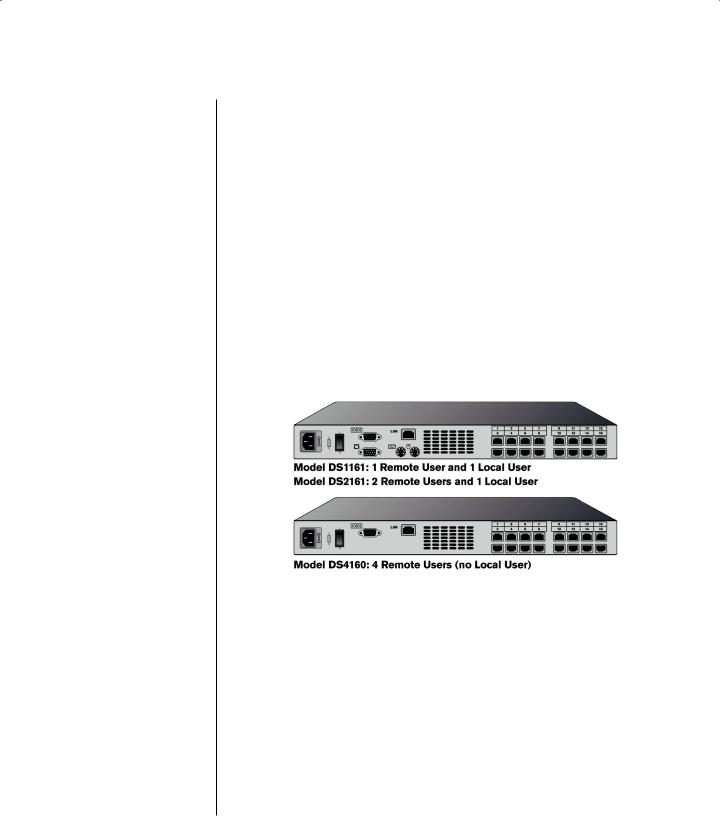
The DSR consists of a rack-mountable KVM switch configurable for analog or digital connectivity. Models currently available include the DSR1161, the DSR2161 and the DSR4160. Each DSR model has 16 input ports and provides enhanced video quality of 1280 x 1024 for digital users (up to 10 meters) and 1600 x 1280 for the local user.
The DSR works over standard LAN connections. Up to four simultaneous users can access servers across a 100BaseT Ethernet connection or directly through a local port on the DSR for digital KVM and administration, depending on the model selected. The IP-based DSR appliance gives you flexible server management control from anywhere in the world.
Reduce cable bulk
With server densities ever increasing, cable bulk remains one of the major concerns of every network administrator. The DSR significantly relieves KVM cable volume in the rack by utilizing the innovative DSRIQ cable and single CAT 5 cabling. This allows you higher server density while providing greater airflow and cooling capacity. The DSRIQ cable is powered directly from the server and provides Keep-alive functionality whether or not the DSR unit is powered up.
Access the DSR via network connection
No special software or drivers are required on the attached, or Host, computers. Users access the DSR unit and all attached systems via Ethernet from a PC running the DSView application. This software resides on the user PC. User

4 DSR Installer/User Guide
PCs can be located anywhere a valid network connection exists. The DSR unit can be configured on a separate network from your data network, allowing access to your servers even if your applications network is down.
DSView provides simple point and click access to any server
When a user connects, the DSView application will display a listing of all computers and serial devices to which the user has permission to access. When a user selects a computer from the list, the video of the selected computer is displayed in the program window. Multiple servers can be accessed by one user. Each additional computer’s video will appear in a separate program window.
DSAdmin and DSAuthentication Service create and manage user permissions with DES encrypted security
An administrator describes the configuration of computers attached to the DSR using an application called DSAdmin. Once the topology is described, the administrator then establishes which computers a user has permission to access. Usernames and passwords are derived from Windows NT, eliminating the need for redundant user databases. Once the topology is established, the DSAuthentication Service software manages the system’s user permissioning. DSView polls the server for access permissions on power-up and every time a switch is initiated for the most current permissions possible. A refresh is also available for immediate updates to a user’s access profile. In addition to the permissioning function, the DSAuthentication Service also stores pertinent
information about attached devices in a database. Room location, rack location and computer type can all be stored for quick reference.
Safety Precautions
ENGLISH
To avoid potential video and/or keyboard problems when using Avocent products, ensure that the computer and monitor are on the same phase if the building has 3-phase AC power. For best results, they should be on the same circuit.
To avoid potentially fatal shock hazard and possible damage to equipment, please observe the following precautions:
•Do not use a 2-wire power cord in any Avocent product configuration.
•Test AC outlets at computer and monitor for proper polarity and grounding.
•Use only with grounded outlets at both the computer and monitor. When using a backup power supply (UPS), power the computer, the monitor and the DSR unit off the supply.
NOTE: The AC inlet is the main disconnect.
Chapter 1: Product Overview |
5 |
|
|
Rack Mount Safety Considerations
•Elevated Ambient Temperature: If installed in a closed rack assembly, the operation temperature of the rack environment may be greater than room ambient. Use care not to exceed the rated maximum ambient temperature of the unit.
•Reduced Air Flow: Installation of the equipment in a rack should be such that the amount of airflow required for safe operation of the equipment is not compromised.
•Mechanical Loading: Mounting of the equipment in the rack should be such that a hazardous condition is not achieved due to uneven mechanical loading.
•Circuit Overloading: Consideration should be given to the connection of the equipment to the supply circuit and the effect that overloading of circuits might have on overcurrent protection and supply wiring. Consider equipment nameplate ratings for maximum current.
•Reliable Earthing: Reliable earthing of rack-mounted equipment should be maintained. Pay particular attention to supply connections other than direct connections to the branch circuit (e.g. use of power strips).


C H A P T E R 2
Installation
Contents
Getting Started . . . . . . . . . . . . . . . . . . . . . . . . . .9 Installing the DSR Unit . . . . . . . . . . . . . . . . . .10 Installing the DSAuthentication Service . . . .13 Installing DSAdmin . . . . . . . . . . . . . . . . . . . . .14 Installing DSView . . . . . . . . . . . . . . . . . . . . . .14 Adding a DSR to the System . . . . . . . . . . . . . .15 Configuring Host PCs . . . . . . . . . . . . . . . . . . .16 Configuring DSAdmin . . . . . . . . . . . . . . . . . .16

Chapter 2: Installation |
9 |
|
|
Chapter 2 – Installation
The DSR system requires that the DSView, DSAdmin and DSAuthentication Service software be installed prior to use. DSView is the application that allows a user to view and control a server attached to the DSR system. DSAdmin is used to configure and maintain the system. DSAuthentication is a Windows NT or 2000 service used to prevent unauthorized access to the DSR system.
NOTE: The local port, on models DSR1161 and DSR2161, does not require the DS software for operation. The local port uses OSCAR, Avocent’s on-screen confi guration and activity reporting interface. For more information, see Chapter 5.
The DSR system uses Ethernet networking infrastructure and TCP/IP protocol to transmit keyboard, video and mouse information between operators and connected computers. Although 10BaseT Ethernet may be used, Avocent recommends a dedicated, switched 100BaseT network.
Getting Started
Before installing your DSR, refer to the list below to ensure you have all items that shipped with the DSR as well as other items necessary for proper installation.
Supplied with the DSR
•DSR Unit
•Local country power cord
•Rack mounting brackets
•Null modem cable
•DSR Installer/User Guide and Software CD
•DSR Quick Install
Additional items needed
•One DSRIQ cable per server
•One CAT 5 patch cable per server (up to 10 meters)
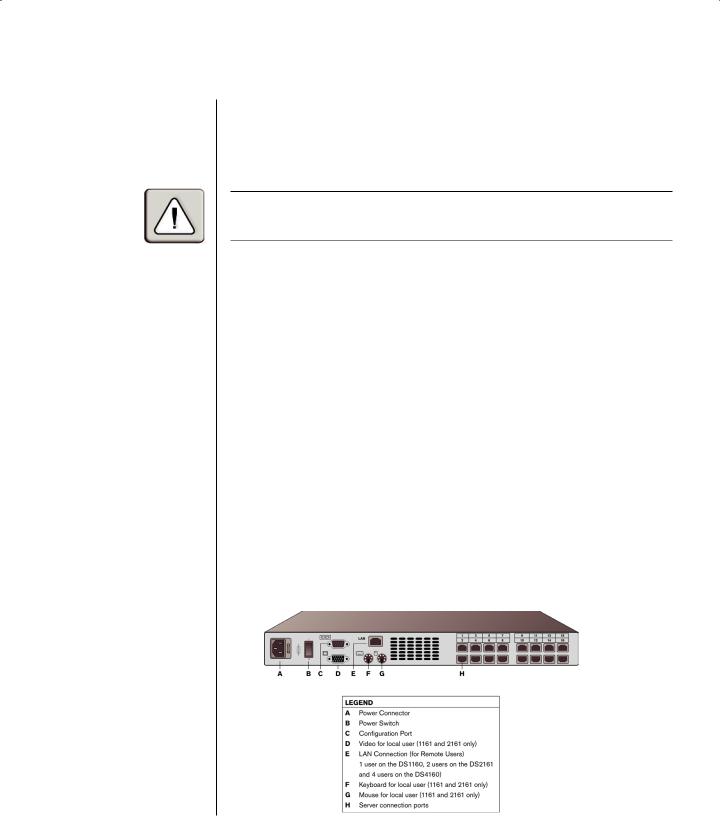
The DSR unit
10 DSR Installer/User Guide
Verification of Ethernet/computer connections
The front panel of the DSR features two LEDs describing the Ethernet connection. The top LED is the Link indicator. It will illuminate when a valid connection to the network is established and blink when there is activity on the port. The lower amber LED, labeled 100Mbps, will indicate that you are communicating at the 100Mb rate.
Additionally, there are two LEDs above each port number on the front of your unit: one green and one amber. The green LED will illuminate when the attached system is powered-on. The amber LED will illuminate when that port is selected by the DSView Client.
Setting up your network
The DSR system uses IP addresses to uniquely identify the DSAuthentication Server, the DSR units and the computers running DSView. The DSR supports both bootP (a subset of DHCP) and Static IP addressing. Avocent recommends that IP addresses be reserved for each unit and that they remain static while the DSR units are connected to the network. For additional information on how the DSR uses the TCP protocol, see Appendix D.
Installing the DSR Unit
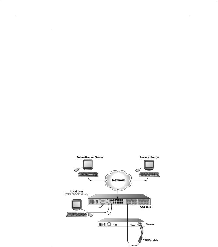
Follow the lettered and numbered instructions below to successfully install your DSR unit. The figure below illustrates one possible configuration.
Chapter 2: Installation |
11 |
|
|
A. To install the DSR hardware
1.Remove the DSR unit from the packing material.
2.Connect a terminal or PC running terminal emulation software (such as HyperTerminal) to the Configuration Port on the back panel of the DSR using the supplied null-modem cable. The terminal should be set to 9600 baud, 8 bits, 1 stop bit, no parity, no flow control.
3.Plug the supplied power cord into the back of the DSR unit and then into an appropriate power source.
4.When the power is switched on, the Power indicator on the front of the unit will blink for approximately 30 seconds while performing a self-test. Approximately 10 seconds after it stops blinking, press the Enter key to access the main menu.
B. To configure the DSR hardware
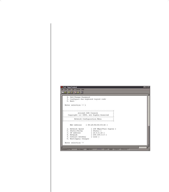
1.You will see the Terminal Applications menu with six options. Select Option 1, Network Configuration.
2.Select Option 1 to set your network speed. When possible, you should set your connection manually without relying on the auto negotiate feature. Once you enter your selection, you will be returned to the Network Configuration menu.
3.Select Option 2 and specify if you are using a static or bootP IP address. Avocent recommends using a static IP address for ease of configuration. If you are using a bootP address, please configure your bootP server to provide an IP address to the DSR, and skip to procedure C.
4.Select options 3-5 from the Terminal application menu in turn to finish
12 DSR Installer/User Guide
configuring your DSR for IP Address, Netmask and Default Gateway. Once this is completed, type a 0 to return to the Main menu.
C. To adjust the mouse acceleration
NOTE: We highly recommend that all Windows systems attached to the DSR use the default Windows PS/2 mouse driver.
Before a PC running Windows NT or 2000 can be connected to the DSR, an adjustment to mouse acceleration must be made. Follow the steps below.
For Windows NT (using default drivers):
1.From the Desktop, select Start - Settings - Control Panel – Mouse.
2.Click on the Motion tab.
3.Set the pointer speed to slow. This will also need to be done for any NT user account that will be accessing the NT system through the DSR.
For Windows 2000:
1.From the Desktop, select Start - Settings - Control Panel - Mouse.
2.Click on the Motion tab.
3.Set the Acceleration setting to none and the speed setting to the default of 50%.
D. To connect a DSRIQ cable to each server
1.Locate the DSRIQ cables for your DSR unit.
2.Attach the appropriately color-coded cable ends to the keyboard, monitor and
mouse ports on the first server you will be connecting to this DSR unit.
4.Attach one end of the CAT 5 cabling that will run from your DSRIQ to the DSR unit to the RJ45 connector on the DSRIQ cable.
5.Connect the other end of the CAT 5 cable to the desired port on the back of your DSR unit.
6.Repeat this step for all servers you wish to attach.
NOTE: Power down the DSR unit before servicing. Always disconnect the power cord from the wall outlet.
E.To connect the local port keyboard, monitor and mouse
(1161 and 2161 models only)
Attach your keyboard, monitor and mouse cable connectors to the appropriate
ports on the back of your DSR unit.
F.To connect and power up your DSR
1.Connect your network cable from the LAN port on the rear of the DSR to your network.
2.Then power up all attached systems.
NOTE: Your software registration key will be necessary for all installations. Internet Explorer 5.0 or higher must be installed on all systems running DSR software.
Chapter 2: Installation |
13 |
|
|
Installing DSAuthentication Service
The DSAuthentication Service manages the level of access users have to system servers as well as the topology and connections for the system. For each attached computer, the DSAuthentication Service also stores pertinent system information in a database for easy retrieval by system administrators. This database is for information only and is not involved in the permissioning function of the DSAuthentication Service.
NOTE: The DSAuthentication Service MUST be installed on a PC running Windows 2000 Service Pack 1 or Windows NT 4.0 Service pack 4 or higher on an NTFS hard drive partition.
To install the DSAuthentication Service software
NOTE: You will need to reboot your system as part of the installation process and log-in as
Administrator. This is necessary for Windows to properly register the new application.
If you are installing from the DSR software CD
1.Insert the DSR Software CD. An autorun file will bring up a menu of installation options.
2.When prompted to select a program to install, select Install DSAuthentication Server. The installation will begin.
3.Follow the on-screen instructions. Windows will determine if the Microsoft Windows Installer Service is available. If it is not, Windows will install it and reboot the system. Setup will automatically continue after the reboot.
4.The Installer will determine if the MDAC components need to be installed. If so, they will be loaded and the system will reboot. Setup will automatically continue after the reboot.
5.Finally, the installer will install the DSAuthentication Service and reboot.
If you are downloading the DSR software from Avocent
1.Using your DSR User Documentation and Software Download Instructions sheet, download the DSR software from the Avocent website.
2.Double-click on the executable downloaded from Avocent. The installation will begin.
3.Follow the on-screen instructions. Windows will determine if the Microsoft Windows Installer Service is available. If it is not, Windows will install it and reboot the system. Setup will automatically continue after the reboot.
4.The Installer will determine if the MDAC components need to be installed. If so, they will be loaded and the system will reboot. Setup will automatically continue after the reboot.
5.Finally, the installer will install the DSAuthentication Service and reboot.

14 DSR Installer/User Guide
Installing DSAdmin
DSAdmin is the administrative front end for the DSAuthentication Service. It controls user information and access levels. DSAdmin can be installed on the same machine as the DSAuthentication Service or a separate machine and connect to the DSAuthentication Server through the network. You will need to log-in as Administrator to proceed.
To install DSAdmin:
If you are installing from the DSR software CD
1.Insert the DSR Software CD. An autorun file will bring up a menu of installation options.
2.When prompted to select a program to install, select DSAdmin.
3.Follow the on-screen instructions.
If you are downloading the DSR software from Avocent
1.Using your DSR User Documentation and Software Download Instructions, download the DSR software from the Avocent website.
2.Double-click on the executable downloaded from Avocent. The installation will begin.
3.Follow the on-screen instructions.
4.During the installation, a window will appear. You will need to enter the name or IP address of the PC where the DSAuthentication Service is installed.
Installing DSView
The DSView software displays a listing of servers that an individual user can access. The DSAuthentication Service will check your NT Domain credentials and provide a list of servers available to you. There is a refresh option in the event that a new server is added, changed or deleted. Once you have selected a server from the list, the video of the selected system will be displayed in
a Session window on the user monitor. DSView can be installed on any PC running a Win32 platform. You will need to log-in as Administrator to proceed.
To install DSView:
If you are installing from the DSR software CD
1.Insert the DSR Software CD. An auto-run file will bring up a menu of installation options.
2.You will be prompted to select a program to install. Select DSView.
3.Follow the on-screen instructions.
Chapter 2: Installation |
15 |
|
|
If you are downloading the DSR software from Avocent
1.Using your DSR User Documentation and Software Download Instructions sheet, download the DSR software from the Avocent website.
2.Double-click on the downloaded executable. The installation will begin.
3.Follow the on-screen instructions.
4.During the installation, the Select Authentication Server Name window will appear. You will need to browse for and select the name of the PC where the DSAuthentication Service is installed.
Adding a DSR to your System
Once you have installed your hardware and software, you will need to configure the system for use.
To configure your system to add a DSR unit:
1.Launch the DSAdmin software.
2.Double-click on the icons labeled Topology and then Your Network. A listing of all DSR units accessible by the system will be displayed.
To add a new DSR unit to the system:
1.From the main DSAdmin menu, select File - New - DSR. The New DSR window will appear.
2.Under the DSR tab, enter the IP Address for the DSR unit that you are adding. This is the IP address that you assigned in the Terminal Applications menu. (See Terminal Applications in this chapter.) Under the Port tab, you can give your servers unique names.
3.Configure each individual port as shown later in this chapter.

16 DSR Installer/User Guide
Configuring Host PCs
A computer attached through a DSRIQ cable to a DSR unit is called a Host PC. If you are attaching a Host PC, you can give it a descriptive name in the port field. No further configuration is necessary.
Configuring DSAdmin
When DSAdmin is activated, the topology of all Host PCs that may be accessed system-wide is displayed in a tree structure. This tree structure can be displayed in two ways: a topology view showing servers and the DSR unit they’re connected to and a server view that shows all available servers.
For the topology view, the first level of the tree is the network IP addresses of the DSR units in the system. To display this level, click on Topology and then
Your Network. Each IP address listed may be expanded by double-clicking on it. This will display the sixteen ports for the DSR corresponding to that address. Each of these ports shares the DSR’s IP address.
If a computer is attached to the port, the properties of the port will be the same as the properties of the computer.
IP Address options
You may right click on any IP address and bring up five options: Collapse, Expand, Properties, Delete and Permissions.
Collapse
Clicking on this option will hide the port information associated with the selected IP Address.
Expand
Click on this option to display the port information associated with the selected IP Address.
Properties
This option will allow you to enter distinguishing information such as a description or emergency contact information pertaining to the selected DSR unit.
Delete
This menu option will delete the selected DSR unit from DSAdmin.
Chapter 2: Installation |
17 |
|
|
Permissions
This option will allow you to configure access for a DSR unit. The DSR has three levels of access: Administrator, User and None. Administrator access allows you to perform administrator level commands for all channels on the designated DSR unit. User access allows you to view and operate a channel but you will not be able to alter administrator settings for that channel. When permissions on a channel are made, a check will be made to determine if that node has any levels below it. If there are, a prompt will appear asking if the changes should be applied to all levels below the node.
NOTE: By default, all users with access to the system will have administration and user access to every port.
Port options
You may right click on any port and bring up three options: Properties,
Rename and Permissions.
Properties
This option will allow you to enter distinguishing information such as a description or emergency contact information pertaining to the selected port.
Rename
Use this option to change the name of the port.
Permissions
This option will allow you to configure an individual port for access. The DSR has three levels of access: Administrator, User and None. Persons with Administrator access may access administrator level commands for all channels in their permissions profile. Persons with User access may view and operate a channel but can not alter administrator settings for that channel.
When permissions on a node are made, a check will be made to determine if that node has any levels below it. If there are, a prompt will appear asking if the changes should be applied to all levels below the node.
NOTE: By default, all users with access to the system will have administration and user access to every port.
To change default user permissions:
1.Right click on the port or DSR unit you wish to change and select the Permissions option.
2.A user listing will appear. You will see a user listed as Everyone which is configured with the default permissions. Any user you do not set up with
Loading...