


AutoView® 200/400
Installer/User Guide

INSTRUCTIONS
This symbol is intended to alert the user to the presence of important operating and maintenance (servicing) instructions in the literature accompanying the appliance.
DANGEROUS VOLTAGE
This symbol is intended to alert the user to the presence of uninsulated dangerous voltage within the product’s enclosure that may be of sufficient magnitude to constitute a risk of electric shock to persons.
POWER ON
This symbol indicates the principal on/off switch is in the on position.
POWER OFF
This symbol indicates the principal on/off switch is in the off position.
PROTECTIVE GROUNDING TERMINAL
This symbol indicates a terminal which must be connected to earth ground prior to making any other connections to the equipment.

 AutoView® 200/400
Installer/User Guide
Avocent, the Avocent logo and The Power of Being There are trademarks of Avocent Corporation. AutoView and LongView are registered trademarks of Cybex Computer Products Corporation. All other marks are the property of their respective owners.
© 2002 Avocent Corporation. All rights reserved.
USA Notification
Warning: Changes or modifications to this unit not expressly approved by the party responsible for compliance could void the user's authority to operate the equipment.
Note: This equipment has been tested and found to comply with the limits for a Class A digital device, pursuant to Part 15 of the FCC Rules. These limits are designed
to provide reasonable protection against harmful interference when the equipment is operated in a commercial environment. This equipment generates, uses and can radiate radio frequency energy and, if not installed and used in accordance with the instruction manual, may cause harmful interference to radio communications. Operation of this equipment in a residential area is likely to cause harmful interference in which case the user will be required to correct the interference at his own expense.
Canadian Notification
This digital apparatus does not exceed the Class A limits for radio noise emissions from digital apparatus set out in the Radio Interference Regulations of the Canadian Department of Communications.
Le présent appareil numérique n’émet pas de bruits radioélectriques dépassant les limites applicables aux appareils numériques de la classe A prescrites dans le Règlement sur le brouillage radioélectrique édicté par le Ministère des Communications du Canada.
Japanese Notification
Agency Approvals
UL 1950, CSA C22. 2 No. 950, EN60950
FCC part 15A, EN55022, EN50082

 Table of Contents
Chapter 1: Product Overview
Features and Benefits . . . . . . . . . . . . . . . . . . . . . . . . . 3
Compatibility . . . . . . . . . . . . . . . . . . . . . . . . . . . . . . . 6
Safety Precautions . . . . . . . . . . . . . . . . . . . . . . . . . . . 6
Chapter 2: Installation
Getting Started . . . . . . . . . . . . . . . . . . . . . . . . . . . . . . 9 Rack Mounting your AutoView Unit . . . . . . . . . . . . 9 Installing an AutoView Switch . . . . . . . . . . . . . . . . 11 Installing a Multiple Switch System . . . . . . . . . . . . 16 Powering Up the AutoView Switch System . . . . . . 17
Chapter 3: Basic Operations
Viewing and Selecting Channels and Servers . . . . 21 Setting up the On-Screen Display . . . . . . . . . . . . . . 23 Setting User Station Security . . . . . . . . . . . . . . . . . 28 Scanning your AutoView System . . . . . . . . . . . . . . 30 Resetting your Mouse . . . . . . . . . . . . . . . . . . . . . . . 33 Displaying Version Information . . . . . . . . . . . . . . . 33 Keyboard Switching . . . . . . . . . . . . . . . . . . . . . . . . 33
Chapter 4: Advanced Operations
Multiuser Operation . . . . . . . . . . . . . . . . . . . . . . . . 39 Keyboard Translation (AutoView 400 only) . . . . . 40
Appendices
Appendix A: FLASH Upgrades . . . . . . . . . . . . . . . . 45
Appendix B: Technical Specifications . . . . . . . . . . 46
Appendix C: Technical Support . . . . . . . . . . . . . . . 47
Appendix D: Troubleshooting . . . . . . . . . . . . . . . . 48

1 Product Overview
Contents
Features and Benefits . . . . . . . . . . . . . . . . . . . . . . . . . 3
Compatibility . . . . . . . . . . . . . . . . . . . . . . . . . . . . . . . 6
Safety Precautions . . . . . . . . . . . . . . . . . . . . . . . . . . . 6

Chapter 1: Product Overview |
3 |
Chapter 1: Product Overview
Features and Benefits
The AutoView 200 and 400 series KVM switches allow you to control multiple computers from one keyboard, monitor and mouse. The AutoView 200 allows you to control up to 64 PCs, while the AutoView 400 enables control of up to 64 PC, Sun or USB computers. Both models work with IBM PC/AT, PS/2 systems and 100% compatible machines with support for VGA, SVGA, XGA and XGA-II video.
SETUP
100-240V , .1A, 50/60 Hz
REMOTE |
LOCAL USER |
A |
C |
E |
G |
USER |
|
||||
|
|
|
|
|
|
I/O |
|
|
|
|
|
|
|
B |
D |
F |
H |
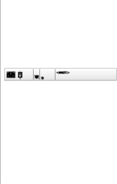
Figure 1.1: AutoView 200 Model
REMOTE |
LOCAL USER |
A |
C |
USER |
|
||
|
|
|
|
I/O |
|
|
|
SETUP |
SUN |
B |
D |
EG
FH
100-240V , .1A, 50/60 Hz
Figure 1.2: AutoView 400 Model
Multiuser/extended access capability
Your AutoView supports two simultaneous users in the system. This second user may be placed up to 500 feet away from the AutoView system. Built-in extension lets you place your second keyboard, monitor and mouse wherever you need them most. Within the base unit, AutoView performs as a complete 2 x 8 matrix switch with both users independently accessing any of the eight attached computers at the same time.
On-screen display capability
Configure and control your AutoView switch with the On-Screen Display (OSD). Name your computer channels anything you wish, then select the desired computer from an easy-to-use menu. Secondary menus let you configure and initiate channel scanning and other system features.
Plug and Play
Your AutoView supports Plug and Play video and is compliant with the VESA DDC2B standard.
Mouse translation
For added compatibility with your current equipment, your AutoView features mouse translation capability. Through the AutoView 200, your PS/2 mouse will work with any attached PC, whether it is serial or PS/2 mouse compatible.
4 AutoView 200/400 Installer/User Guide
With the AutoView 400 switch, your PS/2 mouse will also control Sun and USB computers seamlessly.
Advanced security for total control over system access
Use the advanced multilevel security feature to configure and control server access for every type of user in the system. The administrator has full access privileges, while individual users can have viewing or viewing/editing capability for each attached server.
FLASH upgrade capability
The AutoView 200/400 switches are FLASH upgradable. This allows you to update your firmware at any time through a simple serial connection to insure that your AutoView is always running at its best.
Mouse support
AutoView offers support for numerous PS/2 mice including: IBM ScrollPoint, Logitech MouseMan Wheel, Logitech Trackman Marble Wheel, Logitech Trackman Marble FX, Kensington 4 Button Mouse, Microsoft Explorer Mouse and the Microsoft IntelliMouse family.
|
|
AutoView |
|
|
Secondary |
|
|
Switch (2) |
|
|
LongView |
|
|
Extended |
|
AutoView |
Access |
AutoView |
User |
|
Primary |
|
|
Secondary |
|
|
Switch (1) |
|
|
Switch (3) |
|
|
|
|
|
|
|
Analog |
|
|
User |
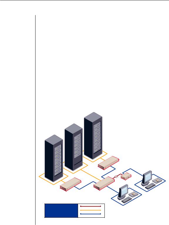
CAT5 Connection
KVM-Connection to Servers
KVM-Connection to Switch
Figure 1.3: Example AutoView 200/400 Configuration
Chapter 1: Product Overview |
5 |
OSD Configuration Utility
The OSD Configuration Utility allows the administrator to easily configure and download a channel list with defined users and access privileges to the entire system. This utility will also read and save your current configuration for extra security.
Expansion for up to 64 computers
Your AutoView unit will support from one to eight attached computers, or channels. If more than eight channels are needed, multiple units can be cascaded together for expansion. Up to two tiers of units can be connected for a total of 64 attached computers in one system.
Built-in scanning capability
A built-in scanning feature allows you to automatically monitor, or scan, connected computers without intervention. When keyboard activity is detected, scanning is suspended until all activity stops. Scanning then resumes with the next channel in sequence.
Keep Alive feature
The AutoView Keep Alive feature allows attached servers to power the unit in the event of an AutoView power failure. This prevents attached computers from locking up and keeps you from losing valuable time and data.
AutoBoot technology
The AutoBoot feature boots all attached servers during initial power up or after a power failure. Computers are booted transparently without operator intervention, and may be powered up one at a time or all at once. When the power stabilizes, a channel may be selected.
Push-button and keyboard switching
In addition to using the on-screen menus, you can switch computer channels in one of three easy ways: via the AutoView channel push-buttons, with the Scan button or with a simple keyboard sequence.
Status indicator LEDs
Indicator LEDs give you constant readings on the status of your AutoView unit. Status, scanning and channel LEDs take the guesswork out of system operation and diagnostics.
Multiplatform (AutoView 400 only)
The AutoView 400 adds multiplatform capabilities to your switching system by simultaneously supporting any combination of PS/2, Sun or USB computers in the same system. Switch easily across platforms with our On-Screen Display.

6 AutoView 200/400 Installer/User Guide
Compatibility
XGA/XGA-II support
If you wish to use XGA or XGA-II video, you will need to purchase an adaptor
available through Avocent.
Safety Precautions
To avoid potential video and/or keyboard problems when using Avocent products:
•If the building has 3-phase AC power, ensure that the computer and monitor are on the same phase. For best results, they should be on the same circuit.
•Use only Avocent-supplied cable to connect computers and KVM switches. Avocent warranties do not apply to damage resulting from user-supplied cable.
To avoid potentially fatal shock hazard and possible damage to equipment,
please observe the following precautions:
•Do not use a 2-wire extension cord in any Avocent product configuration.
•Test AC outlets at the computer and monitor for proper polarity and grounding.
•Use only with grounded outlets at both the computer and monitor. When using a backup power supply (UPS), power the computer, the monitor and the AutoView unit off the supply.
NOTE: The AC inlet is the main disconnect.
Rack mount safety considerations
•Elevated Ambient Temperature: If installed in a closed rack assembly, the operation temperature of the rack environment may be greater than room ambient. Use care not to exceed the rated maximum ambient temperature of the unit.
•Reduced Air Flow: Installation of the equipment in a rack should be such that the amount of airflow required for safe operation of the equipment is not compromised.
•Mechanical Loading: Mounting of the equipment in the rack should be such that a hazardous condition is not achieved due to uneven mechanical loading.
•Circuit Overloading: Consideration should be given to the connection of the equipment to the supply circuit and the effect that overloading of circuits might have on overcurrent protection and supply wiring. Consider equipment nameplate ratings for maximum current.
•Reliable Earthing: Reliable earthing of rack mounted equipment should be maintained. Pay particular attention to supply connections other that direct connections to the branch circuit (for example, use of power strips).

2 Installation
Contents
Getting Started . . . . . . . . . . . . . . . . . . . . . . . . . . . . . . 9 Rack Mounting your AutoView Unit . . . . . . . . . . . . 9 Installing an AutoView Switch . . . . . . . . . . . . . . . . 11 Installing a Multiple Switch System . . . . . . . . . . . . 16 Powering Up the AutoView Switch System . . . . . . 17


Chapter 2: Installation |
9 |
Chapter 2: Installation
Getting Started
Before installing your AutoView system, refer to the lists below to ensure that you have all the items that shipped with the AutoView as well as all other items necessary for proper installation.
Supplied with the AutoView
Your AutoView switch package contains the following items:
•AutoView unit
•Local country power cord
•AutoView 200/400 Installer/User Guide
•AutoView 200 or 400 Quick Installation Guide
•Download Instructions
Optional items
•Rack Mounting Kit (RMK-34)
•Serial cable, DB9 female
•PS/2 (CIFCA), USB (CUSB) or Sun (CVSN or CWSN) cables
•LongView KVM Extender (AVRU)
•CAT 5 cable for LongView (C5T or P5T)
•Sun monitor to VGA adaptor (VAD-13) (AutoView 400 only)
•Sun adaptor kit for LongView (VAK-1) (AutoView 400 only)
Rack Mounting your AutoView Unit
You can either place your AutoView appliance on your desktop or rack mount your unit into an EIA standard rack.
Obtain a Rack Mounting Bracket Kit (1U) from Avocent to rack mount your AutoView. Before installing the switch and other components in the rack, stabilize the rack in a permanent location. Start rack mounting your equipment at the bottom of the rack, then work to the top.
CAUTION: Rack Loading - Overloading or uneven loading of racks may result in shelf or rack failure, causing damage to equipment and possible personal injury. Stabilize racks in a permanent location before loading begins. Mount components beginning at the bottom of the rack, then work to the top. Do not exceed your rack load rating.
CAUTION: Power Considerations - Connect only to the power source specifi ed on the unit. When multiple electrical components are installed in a rack, assure the total component power ratings do not exceed circuit capabilities. Overloaded power sources and extension cords present fi re and shock hazards.
10 AutoView 200/400 Installer/User Guide
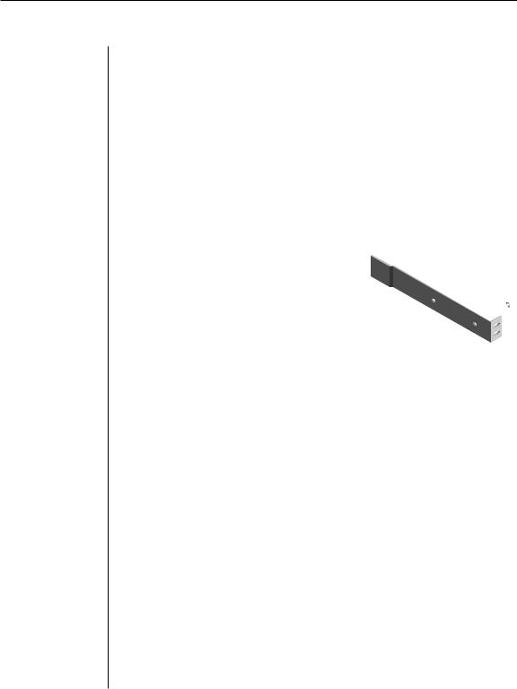
To install the rack mounting bracket:
1.Remove the side screws that secure the cover on your AutoView unit.
2.Line up the holes in the side brackets with the screw holes in the sides of the AutoView unit.
3.Using the previously removed screws, thread one through each of the holes in the sides of the rack mount brackets and into the AutoView cover. Tighten them securely.
4.Install a snap on nut (provided) onto one end of the cable support rod. Insert the rod through both brackets as shown above. Install the remaining acorn nut on the other end of the support rod.
5.Tie wraps can be used to secure cables to the support rod.
Figure 2.1: Rack Mounting Diagram
Chapter 2: Installation |
11 |
Installing an AutoView Switch
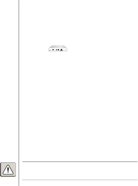
Installing your AutoView 200
The diagram below illustrates one possible configuration for your AutoView 200 switch. Follow the step-by-step procedure To install an AutoView 200/400 switch to properly install your new switch.
Extended Access User |
Local |
(via LongView) |
User |
|
For Sun Only |
RECEIVER
–––+
24VDC |
REMOTE I/O |
.5A
For PS/2 Only
|
|
|
|
|
AutoView 400 |
|
|
REMOTE |
LOCAL USER |
A |
C |
E |
G |
|
USER |
|
||||
|
I/O |
|
|
|
|
|
|
SETUP |
SUN |
B |
D |
F |
H |
100-240V |
, .1A, 50/60 Hz |
|
|
|
|
|
|
DB9 serial port for |
|
|
|
|
|
|
updating firmware |
|
|
|
|
|
|
|
|
|
|
Servers B-H |
|
Server A
Figure 2.2: AutoView 200 Installation Example
WARNING: To reduce the risk of electric shock or damage to your equipment -
-Do not disable the power cord grounding plug. The grounding plug is an important safety feature.
-Plug the power cord into a grounded (earthed) outlet that is easily accessible at all times.
-Disconnect the power from the unit by unplugging the power cord from either the electrical outlet or the unit.

12 AutoView 200/400 Installer/User Guide
Installing your AutoView 400
The diagram below illustrates one possible configuration for your AutoView 400 switch. Follow the step-by-step procedure To install an AutoView 200/400 switch to properly install your new switch.
Extended Access User |
Local |
(via LongView) |
User |
|
For Sun Only |
RECEIVER
–––+
24VDC |
REMOTE I/O |
.5A
For PS/2 Only
|
|
|
|
|
AutoView 400 |
|
|
REMOTE |
LOCAL USER |
A |
C |
E |
G |
|
USER |
|
||||
|
|
|
|
|
|
|
|
I/O |
|
|
|
|
|
|
SETUP |
SUN |
B |
D |
F |
H |
100-240V |
, .1A, 50/60 Hz |
|
|
|
|
|
|
DB9 serial port for |
|
|
|
|
|
|
updating firmware |
|
|
|
|
|
|
|
|
|
|
Servers B-H |
|
Server A
Figure 2.3: AutoView 400 Installation Example
WARNING: To reduce the risk of electric shock or damage to your equipment -
-Do not disable the power cord grounding plug. The grounding plug is an important safety feature.
-Plug the power cord into a grounded (earthed) outlet that is easily accessible at all times.
-Disconnect the power from the unit by unplugging the power cord from either the electrical outlet or the unit.
 Loading...