


DSR800
DSR
Installer/User Guide
For models: DSR800 DSR1161 DSR2161 DSR4160
INSTRUCTIONS
This symbol is intended to alert the user to the presence of important operating and
maintenance (servicing) instructions in the literature accompanying the appliance.
DANGEROUS VOLTAGE
This symbol is intended to alert the user to the presence of uninsulated
dangerous voltage within the product’s enclosure that may be of sufficient
magnitude to constitute a risk of electric shock to persons.
POWER OFF
This symbol indicates the principal on/off switch is in the off position.
POWER ON
This symbol indicates the principal on/off switch is in the on position.
PROTECTIVE GROUNDING TERMINAL
This symbol indicates a terminal which must be connected to earth ground
prior to making any other connections to the equipment.
Avocent, the Avocent logo and The Power of Being There are
trademarks of Avocent Corporation. OSCAR is a registered trade-
mark of Apex Inc. All other marks are trademarks or registered
trademarks of their respective owners.
© 2003 Avocent Corporation. All rights reserved.
DSR
Installer/User Guide
USA Notification
Warning: Changes or modifications to this unit not expressly approved by the party
responsible for compliance could void the user's authority to operate the equipment.
Note: This equipment has been tested and found to comply with the limits for a Class
A digital device, pursuant to Part 15 of the FCC Rules. These limits are designed
to provide reasonable protection against harmful interference when the equipment is
operated in a commercial environment. This equipment generates, uses and can radiate
radio frequency energy and, if not installed and used in accordance with the instruction
manual, may cause harmful interference to radio communications. Operation of this
equipment in a residential area is likely to cause harmful interference in which case the
user will be required to correct the interference at his own expense.
Canadian Notification
This digital apparatus does not exceed the Class A limits for radio noise emissions
from digital apparatus set out in the Radio Interference Regulations of the Canadian
Department of Communications.
Le présent appareil numérique n’émet pas de bruits radioélectriques dépassant les
limites applicables aux appareils numériques de la classe A prescrites dans le Règlement
sur le brouillage radioélectrique édicté par le Ministère des Communications du Canada.
Japanese Approvals
Agency Approvals
UL 1950, CSA C22. 2 No. 950, EN60950, IEC 950
FCC part 15A, EN55022, EN50082
Republic of Korea EMI Standard Certificate Number: E-F900-01-2012 (A)

Table of Contents
Chapter 1: Product Overview
Features and Benefits . . . . . . . . . . . . . . . . . . . . . . . . . 3
Safety Precautions . . . . . . . . . . . . . . . . . . . . . . . . . . . 5
Chapter 2: Installation
Getting Started . . . . . . . . . . . . . . . . . . . . . . . . . . . . . . 9
Installing the DSR Unit . . . . . . . . . . . . . . . . . . . . . . 11
Chapter 3: Local Port Operation
Controlling your System at the Local Port . . . . . . 17
Viewing and Selecting Ports and Servers . . . . . . . . 17
Configuring OSCAR . . . . . . . . . . . . . . . . . . . . . . . . 20
Resetting your Keyboard and Mouse . . . . . . . . . . . 26
Displaying Version Information . . . . . . . . . . . . . . . 27
Chapter 4: Terminal Operations
Accessing the Terminal Menu . . . . . . . . . . . . . . . . . 31
Appendices
Appendix A: FLASH Upgrades . . . . . . . . . . . . . . . . 37
Appendix B: Technical Specifications . . . . . . . . . . 38
Appendix C: Technical Support . . . . . . . . . . . . . . . 39


Contents
Features and Benefits . . . . . . . . . . . . . . . . . . . . . . . . 3
Safety Precautions . . . . . . . . . . . . . . . . . . . . . . . . . . . 5
1
Product Overview


Chapter 1: Product Overview 3
Chapter 1: Product Overview
Features and Benefits
Avocent’s DSR combines analog and digital technology to provide flexible,
centralized control of data center servers. This solution provides enterprise
customers with a significant reduction of cable volume, secure remote access
and flexible server management from anywhere at anytime.
The DSR consists of a rack mountable KVM switch configurable for analog or
digital connectivity. Each DSR model provides enhanced video quality of up to
1280 x 1024 for digital users and 1600 x 1280 for the analog user.
The DSR works over standard LAN connections. Users can access servers
across a 100BaseT Ethernet connection or directly through a local port on the
DSR for digital KVM and administration, depending on the model selected. The
IP-based DSR appliance gives you flexible server management control from
anywhere in the world.
Reduce cable bulk
With server densities ever increasing, cable bulk remains one of the major
concerns of every network administrator. The DSR significantly relieves KVM
cable volume in the rack by utilizing the innovative DSRIQ module and single
CAT 5 cabling. This allows you higher server density while providing greater
airflow and cooling capacity. The DSRIQ module is powered directly from the
server and provides Keep-alive functionality whether or not the DSR unit is
powered up.
Access the DSR via network connection
No special software or drivers are required on the attached, or Host, computers.
Users access the DSR unit and all attached systems via Ethernet from a PC
running the DSView application. This software resides on the user PC. User
PCs can be located anywhere a valid network connection exists. The DSR unit
can be configured on a separate network from your data network, allowing
access to your servers even if your applications network is down.
DSView provides simple point and click access to any server
When a user connects, the DSView application will display a listing of all
computers and serial devices to which the user has permission to access. When
a user selects a computer from the list, the video of the selected computer is
displayed in the program window. Multiple servers can be accessed by one user.
Each additional computer’s video will appear in a separate program window.
4 DSR Installer/User Guide
Chapter 1: Product Overview 5
DSAdmin and DSAuthentication Service create and
manage user permissions with DES encrypted security
An administrator describes the configuration of computers attached to the DSR
using an application called DSAdmin. Once the topology is described, the
administrator then establishes which computers a user has permission to
access. Usernames and passwords are derived from Windows NT, eliminating
the need for redundant user databases. Once the topology is established, the
DSAuthentication Service software manages the system’s user permissioning.
DSView polls the server for access permissions on power-up and every time a
switch is initiated for the most current permissions possible. A refresh is also
available for immediate updates to a user’s access profile. In addition to the
permissioning function, the DSAuthentication Service also stores pertinent
information about attached devices in a database. Room location, rack location
and computer type can all be stored for quick reference.
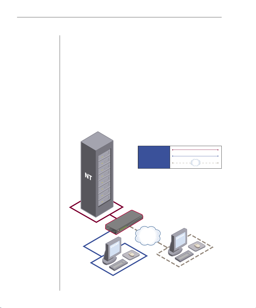
Figure 1.1: Example DSR Configuration
TCP/IP
DSR2161
Digital
User
Analog
User
CAT5 Connection
KVM-Connection to Switch
Digital IP-connection
Chapter 1: Product Overview 5
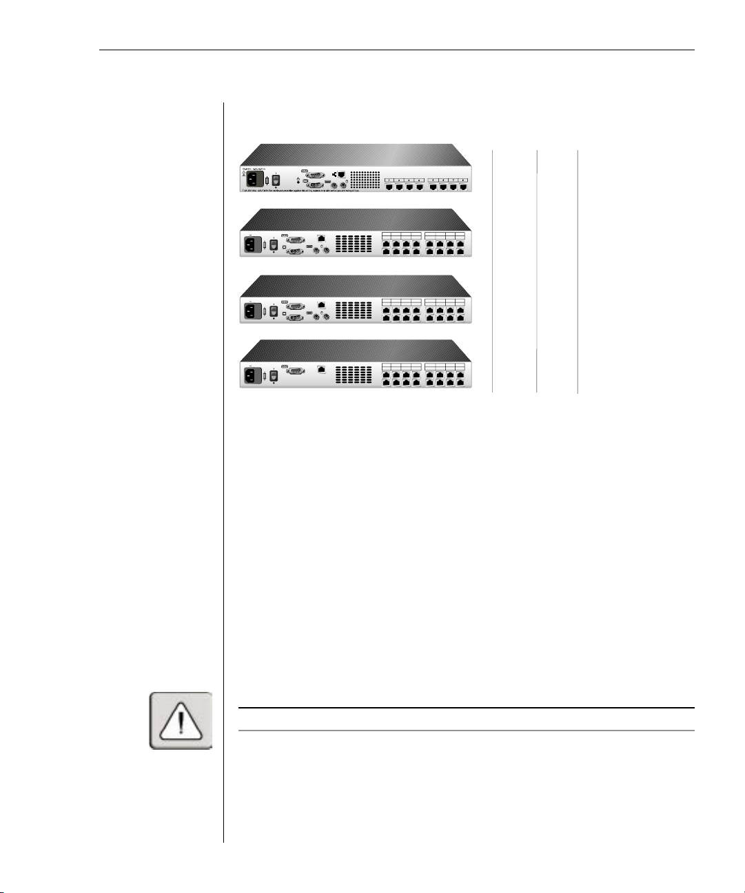
Figure 1.2: DSR Model Comparison
Safety Precautions
To avoid potential video and/or keyboard problems when using Avocent products:
• If the building has 3-phase AC power, ensure that the computer and monitor
are on the same phase . For best results, they should be on the same circuit.
• Use only Avocent-supplied cable to connect computers and KVM switches.
Avocent warranties do not apply to damage resulting from user-supplied cable.
To avoid potentially fatal shock hazard and possible damage to equipment,
please observe the following precautions:
• Do not use a 2-wire power cord in any Avocent product conguration.
• Test AC outlets at computer and monitor for proper polarity and grounding.
• Use only with grounded outlets at both the computer and monitor. When
using a backup power supply (UPS), power the computer, the monitor and
the DSR unit off the supply.
NOTE : The AC inlet is the main disconnect.
DSR 1161
DSR 2161
DSR 4160
Number
of
servers
Digital
users
Analog
user
1 3 5 7 9 11 13 15
2 4 6 8 10 12 14 16
LAN
100-240V
, 1.0A, 50-60 Hz
1 3 5 7 9 11 13 15
2 4 6 8 10 12 14 16
LAN
100-240V
, 1.0A, 50-60 Hz
1 3 5 7 9 11 13 15
2 4 6 8 10 12 14 16
LAN
100-240V
, 1.0A, 50-60 Hz
DSR 800
8 1 1
16 1 1
16 2 1
16 4 0

6 DSR Installer/User Guide
Rack mount safety considerations
• Elevated Ambient Temperature: If installed in a closed rack assembly, the
operation temperature of the rack environment may be greater than room
ambient. Use care not to exceed the rated maximum ambient temperature
of the unit.
• Reduced Air Flow: Installation of the equipment in a rack should be such
that the amount of airow required for safe operation of the equipment is
not compromised.
• Mechanical Loading: Mounting of the equipment in the rack should be such
that a hazardous condition is not achieved due to uneven mechanical loading.
• Circuit Overloading: Consideration should be given to the connection of
the equipment to the supply circuit and the effect that overloading of
circuits might have on overcurrent protection and supply wiring. Consider
equipment nameplate ratings for maximum current.
• Reliable Earthing: Reliable earthing of rack-mounted equipment should
be maintained. Pay particular attention to supply connections other than
direct connections to the branch circuit (e.g. use of power strips).

Contents
Getting Started . . . . . . . . . . . . . . . . . . . . . . . . . . . . . . 9
Installing the DSR Unit . . . . . . . . . . . . . . . . . . . . . . 11
2
Installation


Chapter 2: Installation 9
Chapter 2: Installation
The DSR system requires that the DSView, DSAdmin and DSAuthentication
Service software be installed prior to use. DSView is the application that allows
a user to view and control a server attached to the DSR system. DSAdmin is
used to configure and maintain the system. DSAuthentication is a Windows NT
or 2000 service used to prevent unauthorized access to the DSR system.
NOTE : The local port, on models DSR800, DSR1161 and DSR2161, does not require the DS
software for operation. The local port uses OSCAR, Avocent’s on -screen conguration and
activity reporting interface. For more information, see Chapter 5.
The DSR system uses Ethernet networking infrastructure and TCP/IP protocol
to transmit keyboard, video and mouse information between operators and
connected computers. Although 10BaseT Ethernet may be used, Avocent
recommends a dedicated, switched 100BaseT network.
Getting Started
Before installing your DSR, refer to the list below to ensure you have all items that
shipped with the DSR as well as other items necessary for proper installation.
Supplied with the DSR
• DSR Unit
• Local country power cord
• Rack mounting brackets
• Null modem cable
• DSR Installer/User Guide
• DSR Quick Install
Additional items needed
• One DSRIQ module per server
• One CAT 5 patch cable per server (up to 10 meters)
• DS Software
Verification of Ethernet/computer connections
The front panel of the DSR features two LEDs describing the Ethernet
connection. The top LED is the Link indicator. It will illuminate when a valid
connection to the network is established and blink when there is activity on
the port. The lower amber LED, labeled 100Mbps, will indicate that you are
communicating at the 100Mb rate.
Additionally, there are two LEDs above each port number on the front of your
unit: one green and one amber. The green LED will illuminate when the
 Loading...