


 Loading...
CYCLADES™ ACS 6000
Installation/Administration/User Guide

FCC Warning Statement
The Cyclades ACS 6000 advanced console server has been tested and found to comply with the limits for Class A digital devices, pursuant to Part 15 of the FCC rules. These limits are designed to provide reasonable protection against harmful interference when the equipment is operated in a commercial environment.
This equipment generates, uses and can radiate radio frequency energy and, if not installed and used in accordance with the Installation and Service Manual, may cause harmful interference to radio communications.
Operation of this equipment in a residential area is likely to cause harmful interference in which case the user is required to correct the problem at his or her own expense.
Notice about FCC Compliance for All Cyclades ACS 6000 Advanced Console Server Models
To comply with FCC standards, the Cyclades ACS 6000 advanced console server requires the use of a shielded CAT 5 cable for the Ethernet interface. Notice that this cable is not supplied with either of the products and must be provided by the customer.
Canadian DOC Notice
The Cyclades ACS 6000 advanced console server does not exceed the Class A limits for radio noise emissions from digital apparatus set out in the Radio Interference Regulations of the Canadian Department of Communications.
L’Cyclades ACS 6000 advanced console server n’émete pas de bruits radioélectriques dépassant les limites applicables aux appareils numériques de la classe A prescrites dans le règlement sur le brouillage radioélectrique edicté par le Ministère des Communications du Canada.
Safety and EMC Approvals and Markings
FCC Class A (USA), CE Class A (EU), ICES-003 (Canada), VCCI (Japan), C-Tick (Australia), A-Tick (Australia, with internal modem), UL 60950-1 (USA), cUL (Canada), EN-60950-1 (EU), CB, KCC (Korea), GS, GOSTR (Russia)
This product contains certain free and/or open source components. To request an open source software kit for the open source components used in this product, please complete at FOSS Request Form at http://www.avocent.com/x_For_The_User/Policies/Open_Source_ Policy.aspx.

Cyclades™ ACS 6000
Console Server
Installation/Administration/User Guide
Avocent, the Avocent logo, The Power of Being There, DSView and Cyclades are trademarks or registered trademarks of Avocent Corporation or its affiliates in the U.S. and other countries. All other marks are the property of their respective owners. Internet Explorer and Windows are registered trademarks of Microsoft Corporation in the United States and/or other countries. Firefox is a registered trademark of Mozilla Corporation in the United States and/or other countries. Linux is the registered trademark of Linus Torvalds in the United States and other countries. Sentry is a trademark of Server Technology Inc. Cisco is the registered trademark of Cisco Technology Inc. in the United States and/or other countries. HyperTerminal is the registered trademark of Hilgraeve Inc. in the United States and/or other countries. Java is the registered trademark of Oracle America, Inc. in the United States and/or other countries.
© 2011 Avocent Corporation.
590-767-501E
Symbols Used
NOTE: The following symbolsmayappear within the documentation or on the appliance.
Instructions
This symbol is intended to alert the user to the presence of important operating and maintenance (servicing) instructions in the literature accompanying the appliance.
Dangerous Voltage
This symbol is intended to alert the user to the presence of uninsulated dangerous voltage within the product’s enclosure that may be of sufficient magnitude to constitute a risk of electric shock to persons.
Power On
This symbol indicates the principal on/off switch is in the on position.
Power Off
This symbol indicates the principal on/off switch is in the off position.
Protective Grounding Terminal
This symbol indicates a terminal which must be connected to earth ground prior to making any other connections to the equipment.
Functional Earthing Terminal
This symbol indicates a terminal which serves the purpose of establishing chassis ground equal potential.

ii
TABLE OF CONTENTS
Introduction |
1 |
Features and Benefits |
1 |
Access options |
1 |
Web manager |
2 |
IPv4 and IPv6 support |
2 |
Flexible users and groups |
3 |
Security |
3 |
Authentication |
3 |
VPN based on IPSec with NAT traversal |
3 |
Packet filtering |
4 |
SNMP |
4 |
Data logging, notifications, alarms and data buffering |
4 |
Power management |
4 |
Auto discovery |
4 |
FIPS module |
5 |
Configuration Example |
5 |
Installation |
7 |
Getting Started |
7 |
Supplied with the console server |
7 |
Additional items needed |
7 |
Rack Mounting |
8 |
Connecting the Hardware |
8 |
Console server connectors |
8 |
Connecting device consoles or modems to serial ports |
10 |
Turning On the Console Server |
12 |
Configuring a Console Server |
14 |
Using Telnet or SSH |
14 |
Pluggable Devices Installation and Configuration |
16 |
Accessing the Console Server via the Web Manager |
19 |
Web Manager Overview for Administrators |
19 |

iii Cyclades™ ACS 6000 Advanced Console Server Installation/Administration/User Guide
Wizard Mode |
20 |
Expert Mode |
23 |
Access |
23 |
System Tools |
24 |
System |
24 |
Security |
24 |
Bootp Configuration Retrieval |
26 |
Date and Time |
27 |
Help and Language |
28 |
General |
28 |
Boot Configuration |
29 |
Information |
29 |
Usage |
30 |
Network |
30 |
Settings |
30 |
Devices |
30 |
IPv4 and IPv6 static routes |
31 |
Hosts |
31 |
Firewall |
32 |
IPSec(VPN) |
34 |
SNMP Configuration |
35 |
Ports |
36 |
Serial ports |
36 |
Auxiliary ports |
44 |
CAS Profile |
45 |
Dial-in Profile |
48 |
Pluggable Devices |
50 |
Authentication |
50 |
Appliance authentication |
51 |
Authentication servers |
51 |

Table of Contents |
iv |
Users Accounts and User Groups |
53 |
Local accounts |
54 |
User groups |
55 |
Event Notifications |
62 |
Event List |
62 |
Event Destinations |
62 |
Data Buffering |
63 |
Appliance logging |
64 |
Sensors |
64 |
Power Management |
65 |
PDUs |
65 |
Login |
67 |
Outlet Groups |
67 |
Active Sessions |
68 |
Monitoring |
68 |
Change Password |
69 |
Web Manager Overview for Regular Users |
69 |
Appendix A: Technical Specifications |
73 |
Appendix B: Recovering a Console Server's Password |
75 |
Appendix C: Port Information for Communication with the DSView 3 Software |
76 |
Appendix D: Accessing a Console Server with a DSView 3 Software Installation |
|
via Dial-up |
77 |
Appendix E: Internal Modem |
80 |
Appendix F: Technical Support |
91 |

v Cyclades™ ACS 6000 Advanced Console Server Installation/Administration/User Guide
1
Introduction
1
The Cyclades™ ACS 6000 advanced console server is a 1U appliance that serves as a single point for access and administration of connected devices, such as target device consoles, modems and power devices. Console servers support secure remote data center management and out-of- band management of IT assets from any location worldwide.
NOTE: Unlessnoted, referencesto a console server refer to allmodelsin the 60XXseries.
Console servers provide secure local (console port) and remote (IP and dial-up) access. The console servers run the Linux® operating system with a persistent file system in Flash memory, and can be upgraded from either FTP or a DSView™ 3 management software server.
Multiple administrators can be logged into the console server at the same time and can use the web manager, the Command Line Interface (CLI utility) or DSView 3 software (version 3.6.0.152 and greater) to access and configure the console server.
Two PC card/slots support modem (V.92 and Wireless GSM/CDMA), Ethernet, fast Ethernet (fiber optic) and storage PC cards (16 bit and 32 bit). One USB port supports modem (V.92 and Wireless GSM/CDMA), storage devices and USB hubs. Two fast Ethernet ports support connections to more than one network or configuration of Ethernet bonding (failover) for redundancy and greater reliability. For dial-in and secure dial-back with Point-to-Point Protocol (PPP), optional internal modems can be factory installed, or you can use external modems or wireless modem CardBus devices.
Features and Benefits
Access options
Secure access is available through the following local (analog console port) and remote (digital IP and dial-up) options:
•LAN/WAN IP network connection.

2Cyclades™ ACS 6000 Advanced Console Server Installation/Administration/User Guide
•Dial-up to a factory-configured internal modem (optional), a modem connected either to a serial port or the AUX port (which is only possible when an internal modem is not installed), or to a PC phone card (modem, GSM or CDMA) installed in one of the PC card slots or in the USB port.
•Target device connection. An authorized user can make a Telnet, SSH v1, SSH v2 or Raw connection to a target device. For Telnet or SSH to be used for target device connections, the Telnet or SSH service must be configured in the Security Profile that is in effect.
•Console server console connection. An administrator can log in either from a local terminal or from a computer with a terminal emulation program that is connected to the console port and can use the CLI utility. The CLI utility prompt (--|- cli>) displays at login.
More than one administrator can log into the console server and have an active CLI or web manager session. All sessions receive the following warning message when the configuration is changed by another administrator or by the system: The appliance configuration has been altered from outside of your session. Upon receipt of this message, each administrator needs to verify that changes made during the session were saved.
Web manager
Users and administrators can perform most tasks through the web manager (accessed with HTTP or HTTPS). The web manager runs in Internet Explorer® 6.0 and 7.0, and Firefox® 2 and 3 on any supported computer that has network access to the console server.
An administrator can use the web manager to create user accounts, authorize groups and configure security and ports. Authorized users can access connected devices through the web manager to troubleshoot, maintain, cycle power, reboot connected devices and change their password. For more information on the web manager, see Chapter 3.
IPv4 and IPv6 support
The console server supports dual stack IPv4 and IPv6 protocols. The administrator can use the web manager or CLI to configure support for IPv4 addresses only or for both IPv4 and IPv6 addresses. The following list describes the IPv6 support provided in the console server:
•DHCP
•Dial-in sessions (PPP links)
•DSView software integration
•eth0 and eth1 Ethernet interfaces
•Firewall (IP tables)
•HTTP/HTTPs
Chapter 1: Introduction 3
•Linux kernel
•Remote authentication: Radius, Tacacs+, LDAP and Kerberos servers
•SNMP
•SSH and Telnet access
•Syslog server
NOTE: Remote authentication NFS, NISand IPSecare not supported with IPv6.
Flexible users and groups
An account can be defined for each user on the console server or on an authentication server. The admin and root users have accounts by default, and either can add and configure other user accounts. Access to ports can be optionally restricted based on authorizations an administrator can assign to custom user groups. For more information, see Users Accounts and User Groups on page 53.
Security
Security profiles determine which network services are enabled on the console server. Administrators can either allow all users to access enabled ports or allow the configuration of group authorizations to restrict access. You can also select a security profile, which defines which services (FTP, ICMP, IPSec and Telnet) are enabled and SSH and HTTP/HTTPS access. The administrator can select either a preconfigured security profile or create a custom profile. For more information, see Security on page 24.
Authentication
Authentication can be performed locally, with One Time Passwords (OTP), a remote Kerberos, LDAP, NIS, RADIUS, TACACS+ authentication server or a DSView 3 server. The console server also supports remote group authorizations for the LDAP, RADIUS and TACACS+ authentication methods. Fallback mechanisms are also available.
Any authentication method configured for the console server or the ports is used for authentication of any user who attempts to log in through Telnet, SSH or the web manager. For more information, see Authentication on page 50.
VPN based on IPSec with NAT traversal
If IPSec is enabled in the selected security profile, an administrator can use the VPN feature to enable secure connections. IPSec encryption with optional NAT traversal (which is configured by default) creates a secure tunnel for dedicated communications between the console server

4 Cyclades™ ACS 6000 Advanced Console Server Installation/Administration/User Guide
and other computers that have IPSec installed. ESP and AH authentication protocols, RSA Public Keys and Shared Secret are supported. For more information, see IPSec(VPN) on page 34.
Packet filtering
An administrator can configure a console server to filter packets like a firewall. Packet filtering is controlled by chains, which are named profiles with user-defined rules. The console server filter table contains a number of built-in chains that can be modified but not deleted. An administrator can also create and configure new chains.
SNMP
If SNMP is enabled in the selected security profile, an administrator can configure the Simple Network Management Protocol (SNMP) agent on the console server to answer requests sent by an SNMP management application.
The console server SNMP agent supports SNMP v1/v2 and v3, MIB-II and Enterprise MIB. For more information, see SNMP Configuration on page 35.
NOTE: The text fileswith the Enterprise MIB(ACS6000-MIB.asn) and the TRAPMIB(ACS6000-TRAP-MIB.asn) are available in the appliance under the /usr/local/mibsdirectory.
Data logging, notifications, alarms and data buffering
An administrator can set up data logging, notifications and alarms to alert administrators of problems with email, SMS, SNMP trap or DSView 3 software notifications. An administrator can also store buffered data locally, remotely or with DSView 3 management software.
Messages about the console server and connected servers or devices can also be sent to syslog servers.
Power management
The console server enables users who are authorized for power management to turn power on, turn power off and reset devices plugged into a connected power distribution unit (PDU). The power devices can be connected to any serial port or to the AUX/Modem port (if an internal modem is not installed). For more information, see Power Management on page 65
Auto discovery
An administrator can enable auto discovery to find the hostname of a target connected to a serial port. Auto discovery’s default probe and answer strings have a broad range. An administrator can configure site-specific probe and answer strings. Auto discovery can also be configured through the DSView 3 software.
Chapter 1: Introduction 5
FIPS module
The 140 series of Federal Information Processing Standards (FIPS) are U.S. government computer security standards that specify requirements for cryptography modules.
The console server uses an embedded FIPS 140-2 validated cryptographic module (Certificate No. 1051) running on a Linux PPC platform per FIPS 140-2 Implementation Guidance section G.5 guidelines. For more information, see FIPS module on page 25.
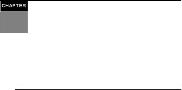
Configuration Example
The following graphic and table illustrate a typical ACS 6000 console server configuration.
Figure 1.1: Typical ACS 6000 Advanced Console Server Configuration

6 Cyclades™ ACS 6000 Advanced Console Server Installation/Administration/User Guide
Table 1.1: Typical ACS 6000 Advanced Console Server Configuration Descriptions
Number |
Description |
Number |
Description |
|
1 |
ACS6000 advanced console server |
8 |
Phone line |
|
2 |
Target devices |
9 |
Remote dial-in client |
|
3 |
PDU (one or more) |
10 |
LocalArea Network(LAN) |
|
4 |
Serialport connection |
11 |
LAN firewall |
|
5 |
PC card (modem, Ethernet or storage) |
12 |
Remote authentication server |
|
|
||||
6 |
Either AUX/Modem or anyserialport |
13 |
DSView client/server |
|
|
Modem ordered and configured internallyat the factory- |
|
|
|
7 |
orExternalmodem (on a device in one of the PC card |
14 |
Remote/localWindows/Linux |
|
slotsor USBport, or connected to a serialport or the AUX |
computer |
|||
|
|
port)

7
Installation
2
Getting Started
Before installing your ACS 6000 console server, refer to the following list to ensure you have all items that shipped with it , as well as other items necessary for proper installation.
Supplied with the console server
•Quick Installation Guide (QIG)
•Power Cord
•RJ-45 to RJ-45 straight-through CAT 5 cable
•RJ-45 to DB-9F cross adaptor
•DB-25 loop-back plug
•RJ-45 to DB-25M cross adaptor
•RJ-45 to DB-25F cross adaptor
•RJ-45 to DM-25M straight-through cable
•Mounting brackets, screws and cord retention clips
•Keyhole mounting kit
•Software License Agreement
•Safety Sheet
Additional items needed
If you are configuring the console server in a standalone configuration, you will also need the following items:
•One or more RJ-45 to RJ-45 CAT 5 straight-through cables
•An RJ-45 to DB-9F straight-through adaptor
8 Cyclades™ ACS 6000 Advanced Console Server Installation/Administration/User Guide
•A PC running a terminal emulation program
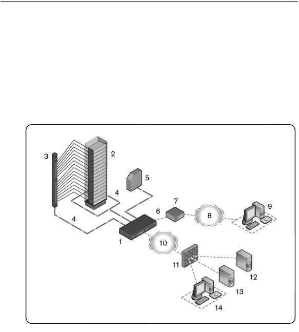
Rack Mounting
You can mount the console server in a rack or cabinet, or place it on a desktop or other flat surface. For rack or cabinet mounting, two mounting brackets are supplied.
To rack mount a console server:
1.Install the brackets at the front or back edges of the console server with the screws provided with the mounting kit.
2.Mount the console server in a secure position.
Figure 2.1: Bracket Connections for Front Mount Configuration
Connecting the Hardware
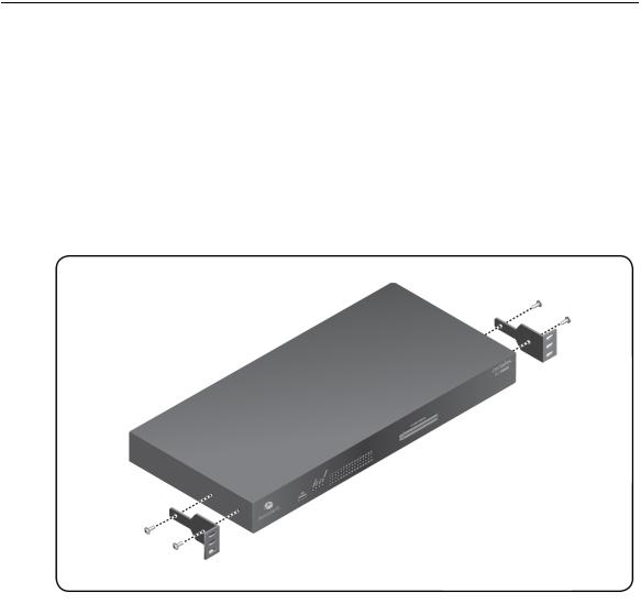
Console server connectors
The following figure shows the connectors on the front of the ACS 6000 console server.
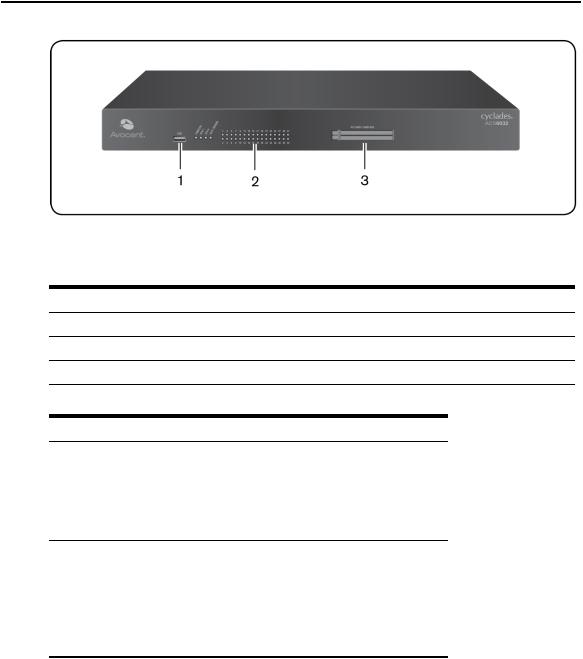
Chapter 2: Installation 9
Figure 2.2: Front of the Console Server (ACS 6032 Console Server Shown) Table 2.1: Connectors on the Console Server Front
Number Description
1USBconnector.
2LEDs.
3PC card slots.
Table 2.2: LEDs on the Console Server Front
Label |
Description |
||
|
Blue |
|
|
PWR/CPU |
• |
BlinksDuring unit boot |
|
• |
Solid - During operation |
||
|
|||
|
• |
Off - Power isoff |
|
|
• |
Amber - Linkat 10BaseT speed |
|
|
• |
Yellow - Linkat 100BaseT speed |
|
ETH 0/ETH 1 |
• |
Green - Linkat 1000BaseT speed |
|
|
• |
Off - No link/cable disconnected/Ethernet |
|
|
|
fault |
|

10 Cyclades™ ACS 6000 Advanced Console Server Installation/Administration/User Guide
Label |
Description |
||
|
DualLED: Yellow on top, green on bottom |
||
AUX/MODEM |
• |
Yellow - DTR/DCD activity |
|
• Green - TXD and RXD activity |
|||
|
|||
|
• Off - No activity |
||
|
Green |
||
[One LED for each serialport] |
• BlinksReady, with activity |
||
• |
Solid - Ready |
||
|
|||
• Off - Not ready
The following figure shows the rear connectors on the console server.
Figure 2.3: Rear of the Console Server (ACS 6032 Console Server Shown)
Table 2.3: Connectors on the Console Server Rear
Number Description
1Power supplies(dualAC shown).
2Serialports(32 portsshown). Modelscome with 4, 8, 16, 32 or 48 serialports.
3ETH 1 10/100M/1GEthernet port. Can be connected to a second networkor used for failover. AUX/Modem port. If an optionalinternalmodem isordered, thisport isdefined asa V.92
4modem at the factory; otherwise, the port isfactory-defined asRS-232 with an RJ-45 ACSconsole server pinout and can be used to connect either an externalmodem or a power device.
5ETH0 10/100M/1GEthernet port for remote IPaccess.
6
Console port. Allowsfor localadministration and accessto connected devicesthrough a terminalor a computer with a terminalemulator.
Connecting device consoles or modems to serial ports
Use CAT 5 or greater cables and DB-9 or DB-25 console adaptors as needed to connect target device consoles or modems to the serial ports on the console server.
The console server supports the Cisco® serial port pinout configuration, which is disabled by default. If a Cisco cable is connected to a port, an administrator must enable the Cisco pinout

Chapter 2: Installation 11
for the port. An administrator can select Expert - Ports - Serial Ports - (SetCAS or SetPower) - Physical to open the Physical Settings screen, then check Enable Cisco RJ Pin-Out.
The following tables show serial port pinout information.
Table 2.4: ACS Console Server Serial Port
Pinout
Pin No. |
Signal Name |
Input/Output |
1 |
RTS |
OUT |
2 |
DTR |
OUT |
3 |
TxD |
OUT |
4 |
GND |
N/A |
5 |
CTS |
IN |
6 |
RxD |
IN |
7 |
DCD/DSR |
IN |
8 |
Not Used |
N/A |
Table 2.5: Cisco Serial Port Pinout |
||
Pin No. |
Signal Name |
Input/Output |
1 |
CTS |
IN |
2 |
DCD/DSR |
IN |
3 |
RxD |
IN |
4 |
GND |
N/A |
5 |
Not Used |
N/A |
6 |
TxD |
OUT |
7 |
DTR |
OUT |
8 |
RTS |
OUT |
To connect devices, modems and PDUs to serial ports:
Make sure the crossover cable used to connect a device has the same pinout type that is configured in the software for the port (either Cyclades or Cisco).
12Cyclades™ ACS 6000 Advanced Console Server Installation/Administration/User Guide
1.Make sure the devices to be connected are turned off.
2.Use CAT 5 or greater crossover cables to connect the devices to the console server, using an adaptor, if necessary.
3.To connect modems, use straight-through CAT 5 or greater cables, with an appropriate connector or adaptor (USB, DB-9 or DB-25) for the modem.
NOTE: To complywith EMC requirements, use shielded cablesfor allport connections.
WARNING: Do not turn on the power on the connected devicesuntilafter the console server isturned on.
To daisy chain PDUs to a console server:
This procedure assumes that you have one PDU connected to a serial port on a console server.
NOTE: Daisychaining isnot possible with SPC PDUs. ServerTech PDUswillallow onlyone level(Master and Slave) of daisychaining.
1.Connect one end of a UTP cable with RJ-45 connectors to the OUT port of the connected PDU.
2.Connect the other end of the cable to the IN port of the chained PDU. Repeat both steps until you have connected the desired number of PDUs.
NOTE: For performance reasons, Avocent recommendsconnecting no more than 128 outletsper serialport.
Turning On the Console Server
The console server is supplied with single or dual AC or DC power supplies.
WARNING: Alwaysexecute the shutdown command through the web manager, CLI or DSView 3 software under the Overview/Toolsnode before turning the console server off, then on again. Thiswillensure the reset doesn't occur while the file system in Flash isbeing accessed, and it helpsavoiding Flash memorycorruptions.
To turn on a console server with AC power:
1.Make sure the console server is turned off.
2.Plug the power cable into the console server and into a power source.
3.Turn the console server on.
4.Turn on the power switches of the connected devices.
To turn on a console server with DC power:
DC power is connected to DC-powered console servers by way of three wires: Return (RTN), Ground (GND) and -48 VDC.
Chapter 2: Installation 13
WARNING: It iscriticalthat the power source supportsthe DC power requirementsof your console server. Make sure that your power source isthe correct type and that your DC power cablesare in good condition before proceeding. Failure to do so could result in personalinjuryor damage to the equipment.
The following diagram shows the connector configuration for DC power.
Figure 2.4: DC Power Connection Terminal Block
Table 2.6: DC Power Connection Details
Number |
Description |
Number |
Description |
1 |
Power switch |
3 |
GND (Ground) |
2 |
RTN (Return) |
4 |
-48 VDC |
1.Make sure the console server is turned off.
2.Make sure DC power cables are not connected to a power source.
3.Remove the protective cover from the DC power block by sliding it to the left or right.
4.Loosen all three DC power connection terminal screws.
5.Connect your return lead to the RTN terminal, your ground lead to the GND terminal and your -48 VDC lead to the -48 VDC terminal and tighten the screws.
6.Slide the protective cover back into place over the DC terminal block.
7.If your console server has dual-input DC terminals, repeat steps 3-6 for the second terminal.
8.Connect the DC power cables to the DC power source and turn on the DC power source.

14Cyclades™ ACS 6000 Advanced Console Server Installation/Administration/User Guide
9.Turn on the console server.
10.Turn on the power switches of the connected devices.
Configuring a Console Server
A console server may be configured at the appliance level through the command line interface accessed through the CONSOLE or Ethernet port. All terminal commands are accessed through a terminal or PC running terminal emulation software.
NOTE: To configure using DSView 3 software, see the DSView 3 Installer/User Guide. To configure using the console server’sweb manager, see Chapter 3. To configure using Telnet or SSH, see the ACS6000 Command Reference Guide.
To connect a terminal to the console server:
1.Using a null modem cable, connect a terminal or a PC that is running terminal emulation software (such as HyperTerminal®) to the CONSOLE port on the back panel of the console server. An RJ-45 to DB9 (female) cross adaptor is provided.
The terminal settings are 9600 bits per second (bps), 8 bits, 1 stop bit, no parity and no flow control.
2.Turn on the console server. When the console server completes initialization, the terminal will display the login banner plus the login prompt.
Using Telnet or SSH
An authorized user can use a Telnet or SSH client to make a connection directly to the console of a device if all of the following are true:
The Telnet or SSH:
•protocol is enabled in the selected security profile
•protocol is configured for the port
•client is available, and it is enabled on the computer from which the connection is made
To use Telnet to connect to a device through a serial port:
For this procedure, you need the username configured to access the serial port, the port name (for example, 14-35-60-p-1), device name (for example, ttyS1), TCP port alias (for example, 7001) or IP port alias (for example, 100.0.0.100) and the hostname of the console server or its IP address.
To use a Telnet client, enter the information in the dialog boxes of the client.
-or-

Chapter 2: Installation 15
To use Telnet in a shell, enter the following command:
# telnet [hostname | IP_address]
login: username:[portname | device_name]
-or-
# telnet [hostname | IP_address] TCP_Port_Alias login: username
-or-
# telnet IP_Port_Alias login: username
To close a Telnet session:
Enter the Telnet hotkey defined for the client. The default is Ctrl ] + q to quit, or enter the text session hotkey for the CLI prompt and then enter quit.
To use SSH to connect to a device through a serial port:
For this procedure, you need the username configured to access the serial port, the port name (for example, 14-35-60-p-1), TCP port alias (for example, 7001), device name (for example, ttyS1), and the hostname of the console server, IP address or IP Port alias (for example, 100.0.0.100).
To use an SSH client, enter the information in the dialog boxes of the client.
-or-
To use SSH in a shell, enter the following command:
ssh -l username:port_name [hostname | IP_address]
-or-
ssh -l username:device_name [hostname | IP_address]
-or-
ssh -l username:TCP_Port_Alias [hostname | IP_address]
-or-
ssh -l username IP_Port_Alias
16 Cyclades™ ACS 6000 Advanced Console Server Installation/Administration/User Guide
To close an SSH session:
At the beginning of a line, enter the hotkey defined for the SSH client followed by a period. The default is ~. Or, enter the text session hotkey for the CLI prompt and then enter quit.
Pluggable Devices Installation and Configuration
Before pluggable devices (PC cards and/or USB devices) can be inserted and configured, pluggable device detection must be enabled.
NOTE: Go to http://www.avocent.com to see the current list of supported pluggable devices. When a pluggable device isnot in the current list of supported pluggable devices, the console server mayattempt to configure the device with standard settings, allowing it to worknormally.
NOTE: When a pluggable device isnot listed in the internaldatabase, the Device Info column mayshow no text at all or show different text based on the type of card. One example isUnknown device f024 (rev01).
To enable Pluggable Device Detection:
1.Select Pluggable Devices in the web manager.
2.Click Enable Pluggable Device Detection.
To install and configure a pluggable device:
1.Insert the PC card into an available slot or connect the USB device.
2.Select Pluggable Devices in the web manager. The Pluggable Devices table is displayed and all detected pluggable devices are shown.
3.Click on the pluggable device name and configure the pluggable device parameters.
NOTE: Storage devicesare automaticallymounted and configured. Configuration of wirelessdevicestakeseffect onlyafter the device isejected and re-inserted.
To eject a pluggable device:
NOTE: Alwaysuse the Web Manager to eject a pluggable device. Anyother method maycause a kernelpanic.
1.Select Pluggable Devices in the web manager.
2.Select the checkbox next to the pluggable device you want to eject, click Eject and remove the pluggable device.
To rename a pluggable device (available for LAN devices):
1.Select Pluggable Devices in the web manager.
2.Check the box next to the pluggable device name you want to rename, then click Rename.
3.Enter the new name and click Save.

Chapter 2: Installation 17

18 Cyclades™ ACS 6000 Advanced Console Server Installation/Administration/User Guide
19
Accessing the Console Server via 3 the Web Manager
Once you’ve connected your ACS 6000 console server to a network, you can access the console server with its web manager. The web manager provides direct access to the console server via a graphical user interface instead of a command-based interface.
NOTE: For instructionson accessing the console server via the CLI or DSView 3 software see the CycladesACS 6000 Command Reference Guide or the DSView 3 Installer/User Guide.
Web Manager Overview for Administrators
NOTE: For an overview of the web manager for regular users, see WebManager Overview for Regular Userson page 69.
To log into the web manager:
1.Open a web browser and enter the console server IP address in the address field.
2.Log in as either admin with the password avocent or as root with the password linux.
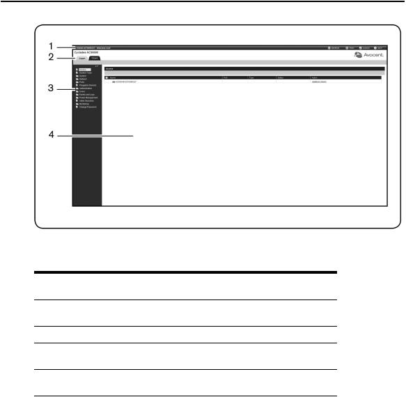
Figure 3.1 shows a typical web manager screen for an administrator and descriptions follow in Table 3.1.
20 Cyclades™ ACS 6000 Advanced Console Server Installation/Administration/User Guide
Figure 3.1: Administrator Web Manager Screen
Table 3.1: Web Manager Screen Areas
Number Description
1
Top option bar. The name of the appliance and of the logged in user appear on the left side. Refresh, Print, Logout and Help buttonsappear on the right.
2 |
Tab bar. Displayswhether the admin isin Expert or Wizard mode. |
3
Side navigation bar. Menu optionsfor configuration, viewing of system information and accessto devices. The optionschange based on user rights.
4
Content area. Contentschange based on the optionsselected in the side navigation bar.
Wizard Mode
The Wizard mode is designed to simplify the setup and configuration process by guiding an administrator through the configuration steps. An administrator can configure all ports in the CAS Profile and set the Security Profile, Network and Users Settings using the Wizard.
Chapter 3: Accessing the Console Server via the Web Manager 21
By default, the first time an administrator accesses the console server through the web manager, the Wizard will be displayed. Subsequent log-ins will open in Expert mode, and once the console server has been configured, Expert mode becomes the default mode. An administrator can toggle between Expert and Wizard modes by clicking the tab bar on the web manager administrator screen.
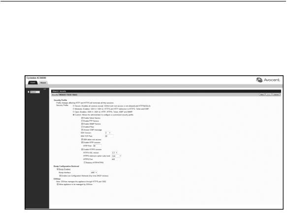
Figure 3.2 shows a typical screen when an administrator is in Wizard mode.
Figure 3.2: Wizard screen
The following procedures describe how to configure the console server from the Wizard.
To configure security parameters and select a Security Profile:
1.Select the Security link in the content area.
2.Select the desired Security Profile. If using a Custom Security Profile, click the checkboxes and enter values as needed to configure the services, SSH and HTTP and HTTPS options to conform with your site security policy.
3.Under the Bootp Configuration Retrieval heading, uncheck the box(es) to disable Bootp configuration retrieval and/or live configuration retrieval.
4.If you are not using DSView 3 software to manage the appliance, uncheck the Allow Appliance to be Managed by DSView box.

22 Cyclades™ ACS 6000 Advanced Console Server Installation/Administration/User Guide
5.Click Next to configure the Network or click the Network, Ports or Users link to open the appropriate screen.
To configure network parameters:
1.Select the Network link in the content area.
2.Enter the Hostname, Primary DNS and Domain in the appropriate fields.
3.Select the IPv4 or IPv6 method for the ETH0 interface. If using Static, enter the Address, Mask and Gateway in the appropriate fields.
4.Click Next to configure ports or click on the Security, Ports or Users link to open the appropriate screen.
To configure Ports:
1.Select the Ports link in the content area.
2.Check the box(es) to enable all ports and/or to enable Cisco RJ45 Pin-Out to change the pin-out when a Cisco cable is connected.
3.Use the appropriate drop-down menus to select the values for Speed, Parity, Data Bits, Stop Bits, Flow Control, Protocol, Authentication Type and Data Buffering Status.
4.Select the Data Buffering Type. If using NFS, enter the NFS Server and NFS Path information in the appropriate fields.
5.Click Next to configure users or click on the Network, Security or Users link to open the appropriate screen.
To configure users and change the default user passwords:
WARNING: For securityreasons, it isrecommended you change the default password for both root and admin
usersimmediately.
1.Select the Users link in the content area.
2.Click a username (admin or root) and enter the new password in the Password and Confirm Password fields.
-or-
Click Add to add a user. Enter the new username and password in the appropriate fields.
3.(Optional) To force the user to change the default password, select the User must change password at next login checkbox.
4.Assign the user to one or more groups.
Loading...