

Page 1

K
Service Source
iMac (Early 2001)
Marketing Reference: Winter 2000-2001
Updated 11 July 2005
Note
: The procedures for this product are almost identical to
the iMac (Summer 2000) computer. To differentiate the two
models, refer to the individual Service Source chapters, the
Knowledge Base, or the Technical Information Library.
© 2001 Apple Computer, Inc. All rights reserved.
Page 2

K
Service Source
T ak e Apart
iMac (Early 2001)
Marketing Reference: Winter 2000-2001
Page 3
Take Apart Version 2, 400 MHz Logic Board (June 2001) - 2
Version 2, 400 MHz
Logic Board (June
2001)
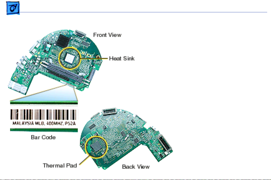
There is a Version 2, 400
MHz logic board for the iMac
(Early 2001), 661-2509.
backward
not
It is
compatible with the earlier
400 MHz board (661-
2427). Exchange like-forlike. Refer to Kbase article
58788 for information on
the iMac logic boards.
The bar code on the Ver. 2
board reads: “400 MHz,
P52A”.
Page 4

Take Apart Version 2, 400 MHz Logic Board (June 2001) - 3
Thermal Pad Replacement
The following logic boards
utilize a thermal pad to help
cool the microprocessor:
661-2509 Ver. 2, 6612425, and 661-2426.
Failure to replace this pad
whenever the logic board is
separated from the divider
panel assembly may cause
the microprocessor to
overheat.
Refer to the Kbase article,
58792, “Microprocessor
Thermal Pad Replacement”
for more information.
Page 5

Take Apart Version 2, 400 MHz Logic Board (June 2001) - 4
The take apart procedures for the iMac (Early 2001)
computers are identical to take apart procedures for iMac
(Summer 2000) slot loading computers. The slot-loading
iMac is referenced in all the pictures in this chapter.
Visible Differences on the iMac (Early 2001):
• White power-on LEDs
• Styles including Blue Dalmation and Flower Power, in
addition to Indigo and Graphite
• The following logic boards utilize the thermal pad (922-
4364) to help cool the microprocessor:
– 661-2509, 400 MHz, Ver. 2
– 661-2425, 500 MHz
– 661-2426, 600 MHz
Page 6

Take Apart Version 2, 400 MHz Logic Board (June 2001) - 5
Tools
The following tools are
recommended for the take
apart procedures:
• phillips screwdriver
(No.1 and No.2)
• a stubby (short) phillips
screwdriver
• plastic flatblade
screwdriver to release
tabs on plastic housing
• jeweler’s screwdriver
• CRT discharge tool
• needlenose pliers
• ESD mat
Page 7
Take Apart Bottom Housing With Flip Foot - 6
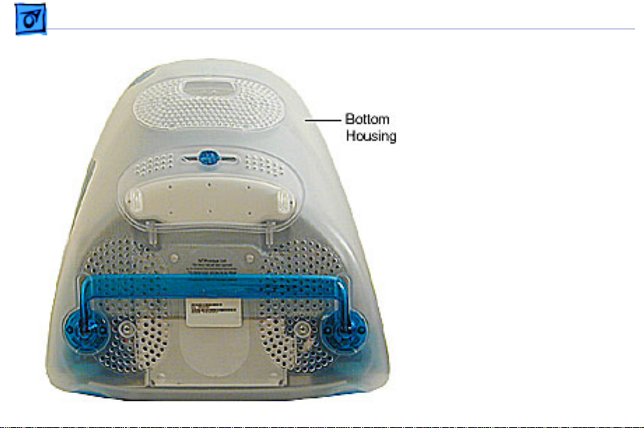
Procedures
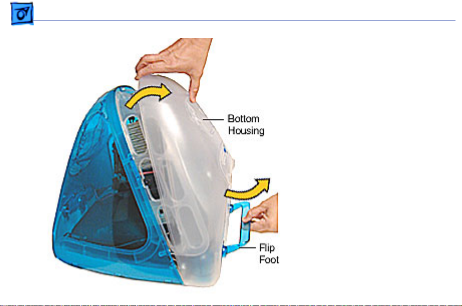
Bottom Housing With Flip Foot
Before you begin, position
the computer face down,
resting the computer on an
ESD mat or other soft
surface.
Page 8
Take Apart Bottom Housing With Flip Foot - 7
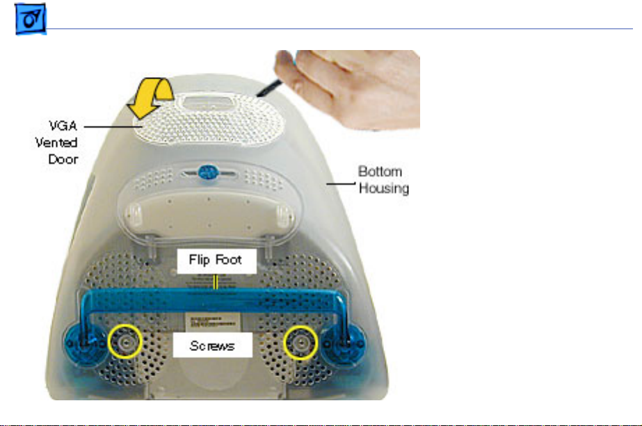
1. Using a plastic flatblade
screwdriver, remove
the VGA vented cover.
2. Remove the two screws
near the flip foot.
Page 9

Take Apart Bottom Housing With Flip Foot - 8
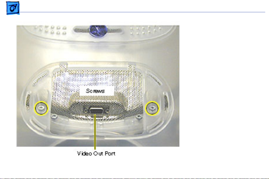
3. Remove the video out
access door from the
bottom housing.
Page 10
Take Apart Bottom Housing With Flip Foot - 9
4. Remove the two outer
screws located near the
video out port.
Replacement Note:
The
bottom housing uses two
sizes of screws. The two
shorter screws attach
near the flip foot.
Page 11
Take Apart Bottom Housing With Flip Foot - 10
5. Pull the bottom housing
off the computer.
Page 12
Take Apart Bottom Housing With Flip Foot - 11
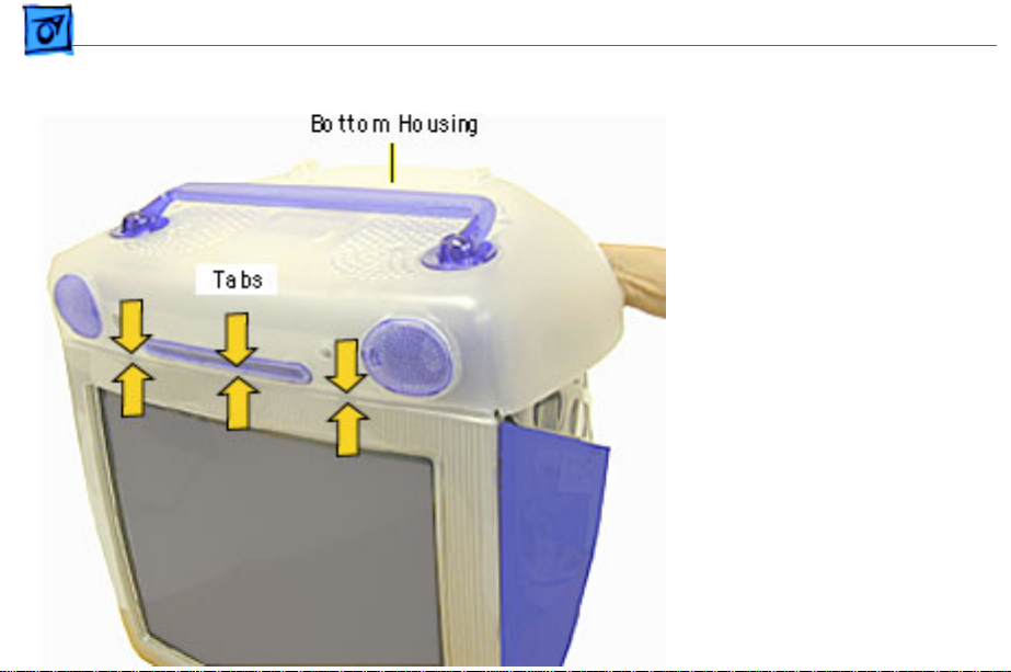
Bottom Housing Replacement Note
1. Align the three tabs on
the bottom housing with
the tab slots on the front
outer bezel.
Ensure that the center
tab is properly aligned
or CDs and DVD discs
may not eject from the
slot.
2. Lower the bottom
housing into place and
replace the screws.
Page 13
Take Apart EMI Cover - 1 2
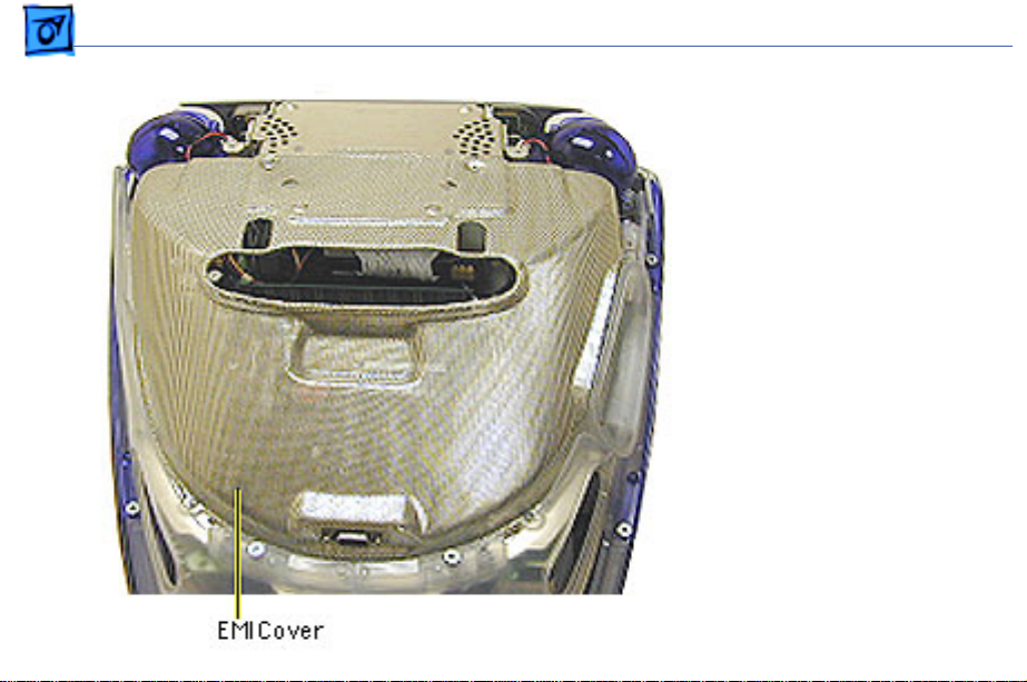
EMI Cover
Before you begin:
• Position the computer
upside down, resting the
computer on an ESD mat
or other soft surface.
• Remove the bottom
housing.
Page 14
Take Apart EMI Cover - 1 3
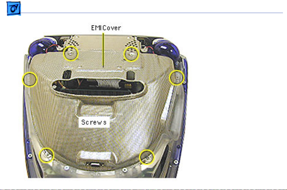
1. Remove the six screws
on the EMI cover.
Page 15
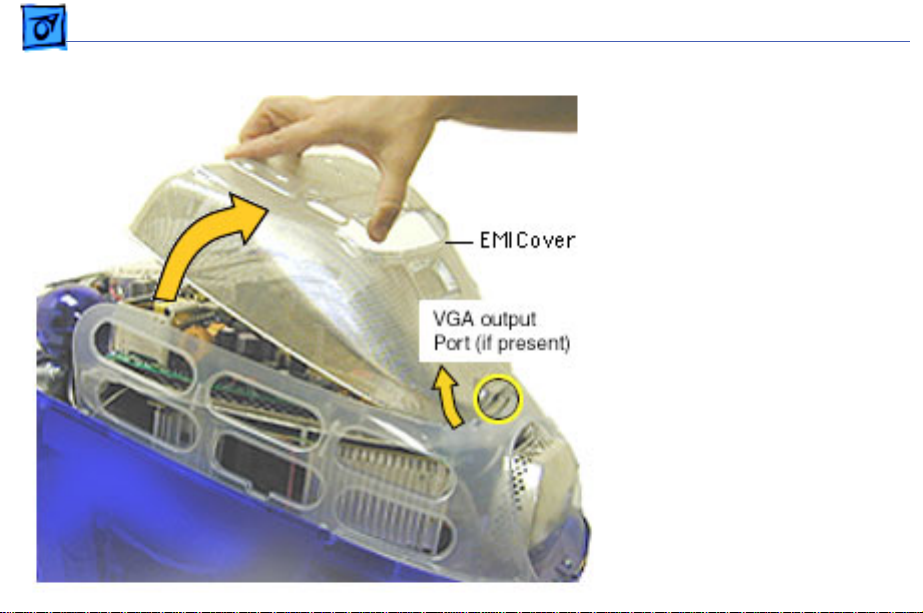
Take Apart EMI Cover - 1 4
2. Lift the EMI cover off the
computer.
Note:
Be careful of the
VGA output port.
Page 16

Take Apart EMI Cover - 1 5
Replacement Note:
Position
the rear of the EMI cover
into place first, positioning
the EMI cover over the video
port (if present). Continue
lowering the cover into
place by gently squeezing in
on both sides, as you lower
the cover into position.
Page 17
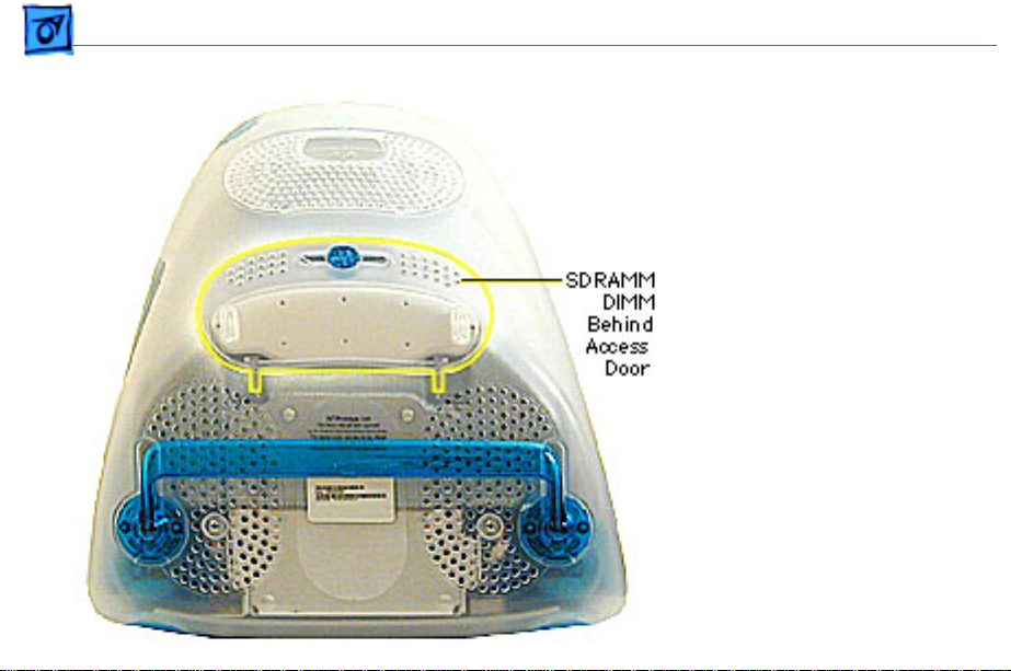
Take Apart SDRAM DIMM - 1 6
SDRAM DIMM
Before you begin, position
the computer face down,
resting the CRT on an ESD
mat or other soft surface.
Page 18
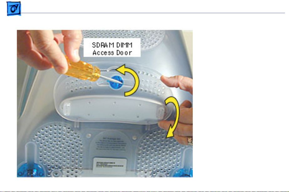
Take Apart SDRAM DIMM - 1 7
1. With a flatblade
screwdriver or coin,
turn the colored latch
counterclockwise on the
access door.
2. Pull the access door
down to open.
Page 19
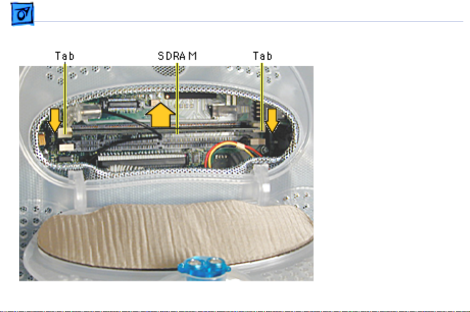
Take Apart SDRAM DIMM - 1 8
3. Push down on the plastic
tabs to release the
SDRAM module(s).
4. Carefully lift the SDRAM
from the slot.
Note:
Remove installed
SDRAM from the logic board
before returning the logic
board to Apple.
Page 20
Take Apart AirPort Card - 19
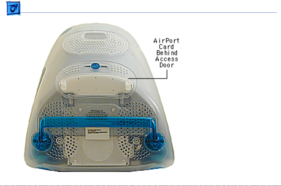
AirPort Card
Before you begin, position
the computer face down,
resting the CRT on an ESD
mat or other soft surface.
If the AirPort Card is
Note:
not installed, a protective
antenna cap will be attached
to the antenna.
Page 21
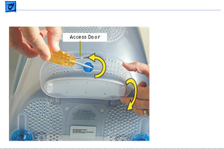
Take Apart AirPort Card - 20
1. With a flatblade
screwdriver or coin,
turn the colored latch to
open the access door.
The antenna and AirPort
Card will be visible
when you open the access
door.
If the AirPort card
Note:
is not installed, a clear
protective antenna cap
will be attached to the
antenna.
Page 22
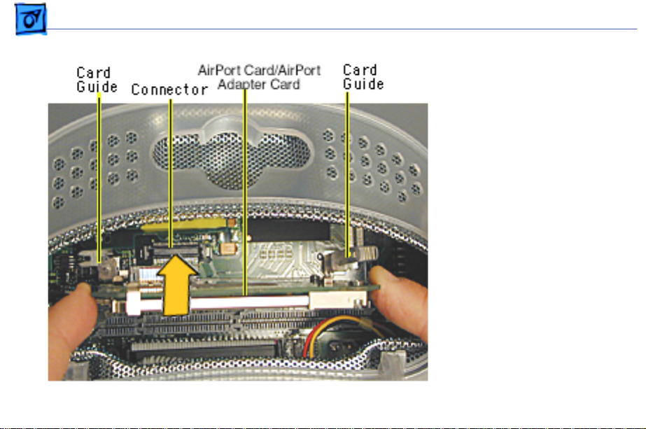
Take Apart AirPort Card - 21
2. Remove the AirPort Card
by lifting the card
straight up and out of the
card guides and
connector.
Page 23
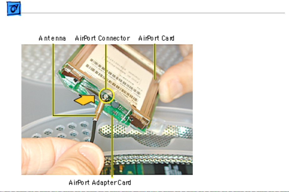
Take Apart AirPort Card - 22
3. Disconnect the antenna
from the small hole
AirPort Card.
Page 24
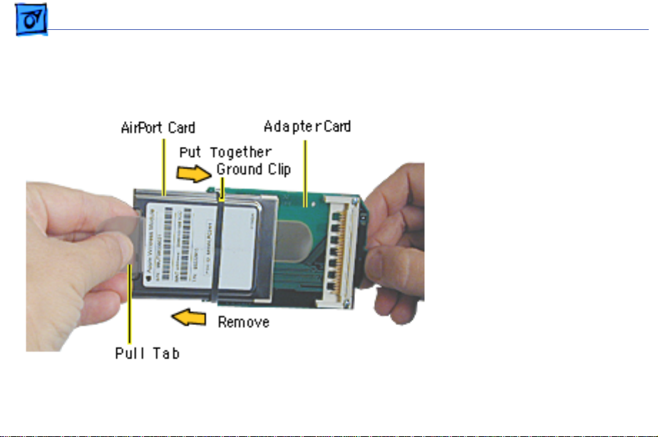
Take Apart AirPort Card - 23
4. Remove the ground clip
from the AirPort
Adapter Card.
5. Using the pull tab,
separate the AirPort
Card from the adapter
card.
Page 25
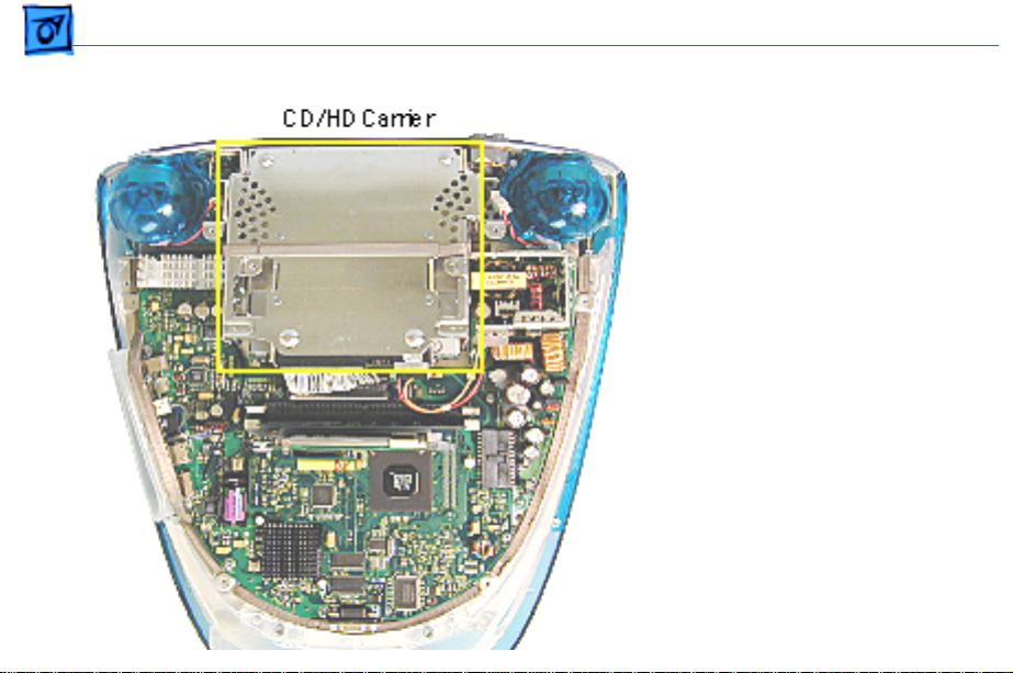
Take Apart CD/HD Carrier - 24
CD/HD Carrier
Before you begin, position
the computer upside down,
resting the computer on an
ESD mat or other soft
surface and remove the
following:
• bottom housing
• EMI cover
• SDRAM
Page 26
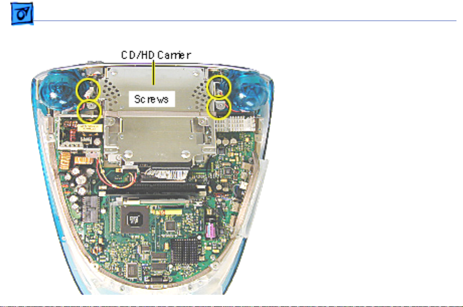
Take Apart CD/HD Carrier - 25
1. Remove the four screws
connecting the CD/HD
drive carrier to the
metal chassis (also
known as the divider
panel).
Page 27
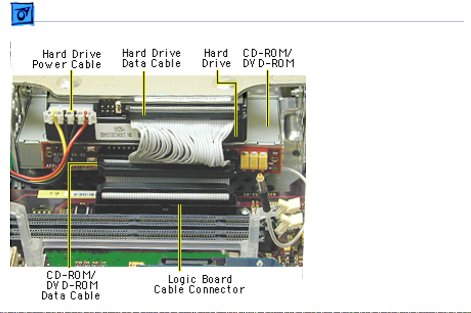
Take Apart CD/HD Carrier - 26
2. Disconnect the following
cables fro the back of the
CD/HD carrier:
• hard drive power
cable
• hard drive data cable
• CD-ROM/DVD-ROM
data cable
• logic board cable
connector
Page 28
Take Apart CD/HD Carrier - 27
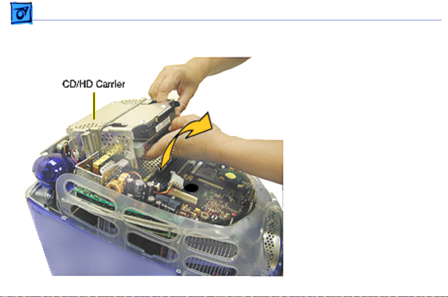
3. Tilt the CD/HD carrier
forward and lift the
carrier out of the
computer.
Continue with the
Note:
Take Apart procedures if you
are replacing the CD-ROM,
DVD-ROM, or the hard
drive.
Page 29
Take Apart CD-ROM / DVD-ROM/CD-RW - 28
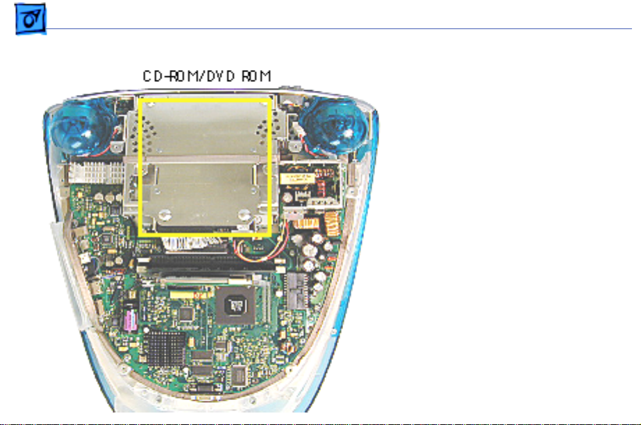
CD-ROM / DVDROM/CD-RW
The procedures for
Note:
removing a CD-ROM, DVDROM and CD-RW are
identical. This procedure
will reference the CD-ROM
Take Apart.
Before you begin, position
the computer upside down,
and remove the following:
• bottom housing
• EMI cover
• SDRAM
• CD/HD carrier
Page 30
Take Apart CD-ROM / DVD-ROM/CD-RW - 29
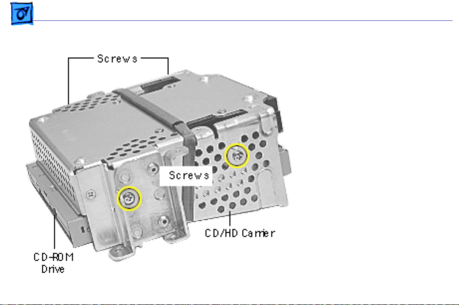
1. Using a Phillips
screwdriver, remove
the CD/HD carrier
mounting screws (two on
each side).
Page 31

Take Apart CD-ROM / DVD-ROM/CD-RW - 30
2. Carefully turn the
CD/HD drive carrier
over.
3. Holding onto the CD-ROM
from the rear, lift the
CD-ROM carrier out of
the CD/HD carrier.
Important:
Don’t press
or squeeze the front of
the CD-ROM. Squeezing
the front could bend the
metal housing, making it
impossible to insert or
remove a CD or DVD disc.
Page 32

Take Apart CD-ROM / DVD-ROM/CD-RW - 31
4. Using a jeweler’s
screwdriver, remove
the four screws (two on
each side) on the CD/
DVD carrier.
5. Lift the CD-ROM from
its carrier.
Page 33

Take Apart CD-ROM / DVD-ROM/CD-RW - 32
6. On the back of the CDROM, Use a jeweler’s
screwdriver to remove
the two screws on the
adapter board.
7. Remove the adapter
board from the CD-ROM.
Return the drive
Note:
to Apple without the
cables, carrier, or the
adapter board. Refer to
the parts database for
more information.
Page 34

Take Apart CD-ROM / DVD-ROM/CD-RW - 33
CD-ROM, DVD-ROM,CDRW Module Replacement
Position the drive into its
carrier as shown.
1. Check that the yellow
warning label is face up.
if you are
Note:
installing a new drive
carrier, remove the blue
film covering the
grounding pad.
Page 35

Take Apart CD-ROM / DVD-ROM/CD-RW - 34
2. Lower the CD/DVD
carrier into the CD/HD
carrier.
3. Push the CD/DVD
carrier forward so the
carrier tabs go through
the holes on the CD/HD
carrier.
4. Replace the CD/HD
carrier screws.
Page 36

Take Apart CD-ROM / DVD-ROM/CD-RW - 35
5. Holding the drive
carrier in the
orientation shown, make
sure the CD-ROM or
DVD-ROM is correctly
installed into the CD/HD
carrier.
6. Make sure the Slave/
Master switch on the
back of the drive is still
set to the Slave mode
(set to the left).
Page 37

Take Apart CD/DVD/CD-RW Adapter Board - 3 6
CD/DVD/CD-RW Adapter Board
Before you begin, position
the computer upside down,
resting the computer on an
ESD mat or other soft
surface and remove the
following:
• bottom housing
• EMI cover
• SDRAM
• CD/HD carrier
Page 38

Take Apart CD/DVD/CD-RW Adapter Board - 3 7
1. Using a jeweler’s
screwdriver, remove
the two screws on the
CD/DVD adapter board.
2. Remove the adapter
board from the back of
the CD-ROM.
Note:
Return the CD/DVDROM drive to Apple without
the cables, carrier, or the
adapter board. Refer to the
parts database for more
information.
Page 39

Take Apart Hard Drive - 38
Hard Drive
Before you begin, position
the computer upside down,
resting the computer on an
ESD mat or other soft
surface and remove the
following:
• bottom housing
• EMI cover
• SDRAM
Page 40

Take Apart Hard Drive - 39
1. Disconnect the following
cables on the back of the
hard drive:
• Hard drive power
cable
• Hard drive data cable
Page 41

Take Apart Hard Drive - 40
The hard drive
Note:
carrier shown was
removed from the
computer. However, you
can easily remove the
hard drive while the
carrier is still screwed
down to the chassis.
Continue with the
procedure.
2. Using a #1 Phillips
screwdriver, remove
the four hard drive
mounting screws.
Page 42

Take Apart Hard Drive - 41
3. Slide the hard drive out
of the CD/HD carrier.
Return the drives
Note:
without the cables or
carriers. Exchange Apple
hard drive modules likefor-like in Apple packaging.
Failure to comply with this
requirement may result in a
packaging noncompliance
charge. Refer to the parts
database for more
information.
Page 43

Take Apart Hard Drive - 42
Hard Drive Replacement
When installing the hard
drive into the CD/HD
carrier, make sure the hard
drive is component side up
(as shown).
Page 44

Take Apart Logic Board - 4 3
Logic Board
Before you begin, position
the computer upside down,
resting the computer on an
ESD mat or other soft
surface and remove the
following:
• bottom housing
• EMI cover
The logic board and the down
converter board are
removed together (still
connected to each other), and
are separated once they are
removed from the computer.
Page 45

Take Apart Logic Board - 4 4
Remove SDRAM to
Note:
make cable removal easier.
1. On the back of the CD/HD
carrier, disconnect the:
• hard drive power
cable
• hard drive data cable
• CD-ROM/DVD-ROM
data cable
• logic board cable
connector
2. Disconnect the antenna if
it’s connected to the
AirPort Card, or it it’s
attached to the protective
antenna cap.
Page 46

Take Apart Logic Board - 4 5
3. Remove the six screws
on the logic board and
five screws on the down
converter board.
Note:
The two screws
located at the top of the
down converter board
(near the speaker) are
larger screws than the
other screws (with
washers).
Page 47

Take Apart Logic Board - 4 6
4. Gently lift the down
converter board and
logic board out of the
computer.
Page 48

Take Apart Logic Board - 4 7
5. Using a flatblade
screwdriver, pry the
plastic rivet off the
board.
Put the top half of the
rivet back into the
bottom half so it doesn’t
get lost.
Page 49

Take Apart Logic Board - 4 8
6. Holding onto the down
converter, press down
on the black connector to
separate the down
converter board from
the logic board.
If you are returning
Note:
the logic board to Apple
refer to the parts database
and remove the SDRAM, any
cables, the modem, the
AirPort Card, and I/O panel.
Replacement Note:
When
reinstalling the logic board,
refer to the next page about
installing a thermal pad.
Page 50

Take Apart Logic Board - 4 9
Thermal Pad
Thermal pad is used on these boards:
661-2509, 400 MHz, Ver. 2
661-2425, 500 MHz
661-2426, 600 MHz
Back View
Front
View
Thermal Pad Information
The thermal pad prevents
the microprocessor from
overheating.
It is crucial that a fresh
thermal pad be used each
time you detach the main
logic board from the divider
panel assembly. (An
exception would be if you
are simply testing the logic
board and only detach it for a
few minutes).
Continue with the procedure
to install the thermal pad.
Page 51

Take Apart Logic Board - 5 0
Thermal Pad Installation
1. Pull the old thermal pad
from the
microprocessor.
2. Remove the protective
backing from either side
of the new thermal pad
Thermal
Pad
and place it on the
microprocessor.
3. Press down on the pad to
make sure it has even
contact without air
pockets.
4. Remove the protective
backing from the exposed
side of the thermal pad.
Page 52

Take Apart Logic Board - 5 1
5. Install the logic board
back on to the divider
panel.
: Avoid unnecessary
Note
contact with either side of
the thermal pad as dirt or
body oils reduce the thermal
conductivity of the pad.
For additional information,
refer to Kbase article
Thermal
58792, “Microprocessor
Thermal Pad Replacement”.
Pad
Divider Panel
Page 53

Take Apart Down Converter Board - 5 2
Down Con verter Board
Before you begin, position
the computer upside down,
resting the computer on an
ESD mat or other soft
surface and remove the
following:
• bottom housing
• EMI cover
The logic board and
Note:
the down converter board
are removed together (still
connected to each other), and
are separated once they are
removed from the computer.
Page 54

Take Apart Down Converter Board - 5 3
Remove SDRAM to
Note:
make cable removal easier.
1. On the back of the CD/HD
carrier, disconnect the:
• hard drive power
cable
• hard drive data cable
• CD-ROM/DVD-ROM
data cable
• logic board cable
connector
2. Disconnect the antenna if
it’s connected to the
AirPort Card, or it it’s
attached to the protective
antenna cap.
Page 55

Take Apart Down Converter Board - 5 4
3. Remove the six screws
on the logic board and
five screws on the down
converter board.
Note:
The two down
converter screws located
near the speaker are
larger screws than the
rest of the down
converter screws.
Page 56

Take Apart Down Converter Board - 5 5
4. Lift the boards out of the
computer.
Page 57

Take Apart Down Converter Board - 5 6
5. Using a flatblade
screwdriver, pry the
rivet off the logic board.
Put the top half of the
rivet back into the
bottom half so it doesn’t
get lost.
Page 58

Take Apart Down Converter Board - 5 7
6. Holding onto the boards,
press down on the black
connector and separate
the down converter
board from the logic
board.
Replacement Note: When
reinstalling the logic
board, make sure the
antenna wire is not
underneath the board.
Page 59

Take Apart Modem - 5 8
Modem
Before you begin, position
the computer upside down,
resting the computer on an
ESD mat or other soft
surface and remove the
following:
• bottom housing
• EMI cover
• logic board
Note: The modem is located
on the underside of the logic
board.
Page 60

Take Apart Modem - 5 9
1. With the logic board
facing right side up,
disconnect the cable at
J12.
2. Remove the two screws
on the I/O panel.
Page 61

Take Apart Modem - 6 0
3. Turn the logic board to
the underside and
remove the modem
screw.
Page 62

Take Apart Modem - 6 1
4. Rotate the logic board
right side up again.
Carefully slide the I/O
panel off the logic board.
Note: As you slide the
I/O panel off the logic
board, support the
modem with your other
hand so the modem
doesn’t fall off the logic
board.
5. Remove the modem from
its connector slot on the
underside of the logic
board.
Page 63

Take Apart Modem - 6 2
Modem Replacement
The I/O panel and the modem
are sandwiched between the
logic board and the metal
frame of the I/O panel. The
metal frame fits on top of the
logic board, over the screw
holes. On the underside of
the logic board, the screw
tab goes under the modem.
Replacement Note: After
replacing an international
modem, use the Modem
Country Selector utility to
set the modem to the correct
country.
Page 64

Take Apart I/O Panel - 6 3
I/O Panel
Before you begin, position
the computer upside down,
resting the computer on an
ESD mat or other soft
surface and remove the
following:
• bottom housing
• EMI cover
• logic board
Page 65

Take Apart I/O Panel - 6 4
1. Disconnect the cable at
J12, going from the
logic board to the I/O
panel.
2. Remove the two screws
on the I/O panel.
Page 66

Take Apart I/O Panel - 6 5
3. Turn the logic board
over and remove the
modem screw.
Page 67

Take Apart I/O Panel - 6 6
4. Rotate the logic board
face up again and
carefully slide the I/O
panel off the logic board.
Note: As you slide the
I/O panel off the logic
board, support the
modem with your hand so
the modem doesn’t fall
off the logic board.
Page 68

Take Apart Front Outer Bezel - 67
Front Outer Bezel
Before you begin, place the
computer on an ESD mat and
remove the bottom housing.
Page 69

Take Apart Front Outer Bezel - 68
1. With a jeweler’s
screwdriver, carefully
remove the two tabs on
the front outer bezel.
Refer to the next graphic
for a close-up of the tab
removal.
Page 70

Take Apart Front Outer Bezel - 69
2. After removing the tabs,
remove the screws
located under the tabs.
Page 71

Take Apart Front Outer Bezel - 70
Note: The bezel tabs fit
tightly into the rear
housing. A good, hard pull
upward is required to
release all the tabs.
3. Insert a plastic tool
underneath the bezel.
4. Pry the outer bezel tabs
from the rear housing
with a plastic tool. As
you push and pry the tool
inside the bezel, the side
tabs will start to
release.
5. Insert the tool on the left
side of the bezel and
repeat.
Page 72

Take Apart Front Outer Bezel - 71
6. As the tabs start to
release, pull hard on the
front outer bezel to
release the tabs
completely.
Page 73

Take Apart Top Rear Housing - 7 2
Top Rear Housing
±Warning: This product
contains high voltage and a
high-vacuum picture tube.
To prevent serious injury,
review CRT safety. From the
Service Source Online home
page, click Troubleshoot and
Repair. Then click on Safety
under the Tools list.
Before you begin, rest the
computer on an ESD mat and
remove the following:
• bottom housing
• front outer bezel
Page 74

Take Apart Top Rear Housing - 7 3
1. Remove the two tabs
(screw caps) on the top
inner bezel. Refer to the
next page for a close-up
of the tab removal.
Page 75

Take Apart Top Rear Housing - 7 4
2. Pry the tabs off, and
remove the two screws
under each tab.
Page 76

Take Apart Top Rear Housing - 7 5
3. Position the computer
face down.
4. Remove four screws and
loosen the fixed screw
(at the top) on the rear
housing.
Page 77

Take Apart Top Rear Housing - 7 6
5. Position the computer
right side up. Push down
and pull out on the rear
housing to unhook the
rear housing tabs that
connect to the inner
bezel.
Page 78

Take Apart Top Rear Housing - 7 7
6. Lift the top rear housing
off the computer.
Page 79

Take Apart Divider Panel - 78
Divider Panel
Many service parts, such as
the speakers, power/
analog/video board, side
panels, cables, and the
headphone board, are
connected to the divider
panel. The divider panel is
the metal chassis with EMI
foam.
The divider panel is not
available as a service part
on the iMac (Early 2001)
computer.
Page 80

Take Apart Divider Panel - 79
The thermal pad (A) and the
divider panel(B) are used on
the following logic boards:
• 661-2509, 400 MHz,
Version 2
• 661-2425, 500 MHz
• 661-2426, 600 MHz
Page 81

Take Apart Power/Analog/Video Board - 8 0
Power/Analog/Video Board
Before you begin, discharge
the CRT, rest the computer
on an ESD mat or other soft
surface and remove the
following:
• bottom housing
• front outer bezel
• top rear housing
Note: There are two power/
analog/video boards, part
number 661-2465 (with a
switch at SW901) and 661-
2466. Exchange like-for-
like.
Page 82

Take Apart Power/Analog/Video Board - 8 1
±Warning: This product
contains high voltage and a
high-vacuum picture tube.
To prevent serious injury,
discharge the CRT.
1. Disconnect the
microphone connector
located near the top of
the CRT.
2. Unwrap the bendable
cable wraps in the upper
left and upper right
corners of the CRT.
3. Disconnect the anode cap.
Page 83

Take Apart Power/Analog/Video Board - 8 2
4. Lift the degauss cable out
of the way to access the
side panel screws.
5. Using a narrow shaft
screwdriver, remove
the four side panel
screws (two on each
side) that attach the left
and right side panels to
the inner bezel.
Page 84

Take Apart Power/Analog/Video Board - 8 3
6. Open the CRT cable
clamps. Remove the
wires from the cable
clamps.
Page 85

Take Apart Power/Analog/Video Board - 8 4
7. Partially lift the side
panels (with the power/
analog/video board
attached to the divider
panel) up and off the
inner bezel to gain
access to connector
P501 located at the
bottom of the power/
analog/video board.
Page 86

Take Apart Power/Analog/Video Board - 8 5
8. Disconnect P501 and
P701 on the power/
analog/video board. The
cables are located near
the high voltage
capacitor.
Page 87

Take Apart Power/Analog/Video Board - 8 6
9. On the other side of the
CRT neck, disconnect the
brown degauss cable,
P901, from the power/
analog/video board.
Remove P901 from the
cable clamp.
Page 88

Take Apart Power/Analog/Video Board - 8 7
10. At the very bottom of the
power/analog/video
board, near the bottom of
the CRT, disconnect
P902, which is part of
the audio/headphone/
LED/speaker cable
assembly.
Page 89

Take Apart Power/Analog/Video Board - 8 8
11. Disconnect the two
ground cables on the
video board.
Important: Be careful when
working around the CRT
neck rings. If the neck rings
are bumped, the CRT will be
knocked out of adjustment,
and will require
replacement of the CRT.
Page 90

Take Apart Power/Analog/Video Board - 8 9
12. Loosen the CRT neck
clamp screw.
Page 91

Take Apart Power/Analog/Video Board - 9 0
13. Carefully pull the video
board off the CRT neck.
Page 92

Take Apart Power/Analog/Video Board - 9 1
14. Holding on to the side
panels, lift the power/
analog/video board
(which is attached to the
side panels and divider
panel) from the inner
bezel.
Page 93

Take Apart Power/Analog/Video Board - 9 2
15. Remove the ten screws
and pinch the two
standoffs with a
needlenose pliers to lift
the power/analog board
off the divider panel.
Page 94

Take Apart Power/Analog/Video Board - 9 3
16. Lift the board from the
flyback transformer
side to clear the power
plug from the side panel.
17. Pull the board forward
toward the speakers.
Replacement Note: If you’re
returning the power/
analog/video board to Apple,
exchange the board likefor-like and leave the cables
attached to the board.
Page 95

Take Apart Power/Analog/Video Board - 9 4
661-2466
661-2465
(with switch at SW901)
Identifying Power/Analog/ Video Boards
There are two power/
analog/video boards in
service stock. The part
numbers are 661-2465 and
661-2466. These boards
must be exchanged like-forlike.
The 661-2465 board can be
identified by the presence of
a switch at location SW901,
located near the flyback
transformer. Refer to the
next page for switch
instructions.
Page 96

Take Apart Power/Analog/Video Board - 9 5
Switch Instructions
If the computer has the
analog board with the
switch, the switch must be
set for the type of the CRT
(LG or CPT) tube in the
computer.
If the power/analog/video
board or the CRT are
replaced, make sure to set
the switch to the
appropriate position.
Refer to the next page for
information on how to
identify an LG and CPT CRT.
Page 97

Take Apart Power/Analog/Video Board - 9 6
LG CRT
Identify an LG CRT by the
black plastic molding located
on the CRT neck. The LG
molding has the LG name at
the top and three holes.
If the computer is using the
661-2465 power/analog
board (with the switch at
SW 901) with an LG CRT,
make sure the switch is set
to LG.
Page 98

Take Apart Power/Analog/Video Board - 9 7
CPT CRT
Identify a CPT CRT by the
black plastic molding located
on the CRT neck. The CPT
molding has two holes in the
molding.
If the computer is using the
661-2465 power/analog
board (with the switch at
SW 901) with a CPT CRT,
make sure the switch is set
to CPT.
Page 99

Take Apart Side Panels - 9 8
Side Panels
±Warning: This product
contains high voltage and a
high-vacuum picture tube.
To prevent serious injury,
discharge the CRT.
Before you begin, discharge
the CRT, rest the computer
on an ESD mat or other soft
surface and remove the
following:
• bottom housing
• front outer bezel
• top rear housing
Page 100

Take Apart Side Panels - 9 9
1. Undo the wire wraps in
the top corners or the
CRT.
2. Lift the degauss cable out
of the way to access the
side panel screws. There
are two screws on each
side.
 Loading...