

Page 1

K
Service Source
iBook
iBook, iBook (FireWire)
Updated December 5, 2002
© 2002 Apple Computer, Inc. All rights reserved.
Page 2

K
Service Source
T ak e Apart
iBook / iBook (FireWire)
© 2002 Apple Computer, Inc. All rights reserved.
Page 3

Take Apart Tools - 1
Tools
Use the following tools for procedures in this chapter:
• Coin the size of a U.S. quarter (to remove battery door)
• 5 mm nut driver
• 4 mm nut driver (to remove sound board on iBook)
• Torx T8 screwdriver
• #0 Phillips screwdriver (for optical drive bezel screws)
• #1 Phillips screwdriver
• Very small jeweler’s flat-head screwdriver (for
keyboard locking screw)
• Flat-blade tool, ESD-safe, non-marring
(such as the nylon probe tool 922-5065)
• I C extractor (to remove display cable connector)
• Fine point needle nose pliers (to adjust handle tension)
Page 4

Take Apart Cables - 2
Cables
Follow these guidelines when working with cables:
• Ensure that all cables are routed exactly as they were
found when reassembling. Use all grooves and/or
protrusions to align cabling. If the cable is improperly
routed, you may not be able to reassemble the computer,
or once reassembled, the computer may fail to function.
• Check that all cables are properly aligned in the
connectors and that the connections are tight.
• Handle flex cables carefully. Using excessive force to
disconnect a cable can tear or damage it so it will not
work properly.
• Use a nylon tool or dental pick to help loosen cable
connections.
Page 5
Take Apart Battery - 3
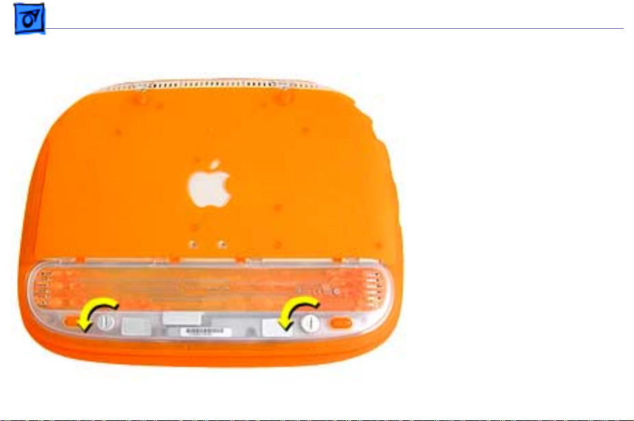
Battery
Before you begin, unplug the
AC adapter.
1. Use a coin to turn the
battery door screws to
the left a quarter turn.
The screws will pop up
but not come out all the
way.
2. Remove the battery door
and pull up on the plastic
tab attached to the
battery to remove it
from the compartment.
Page 6
Take Apart CD-ROM Bezel - 4
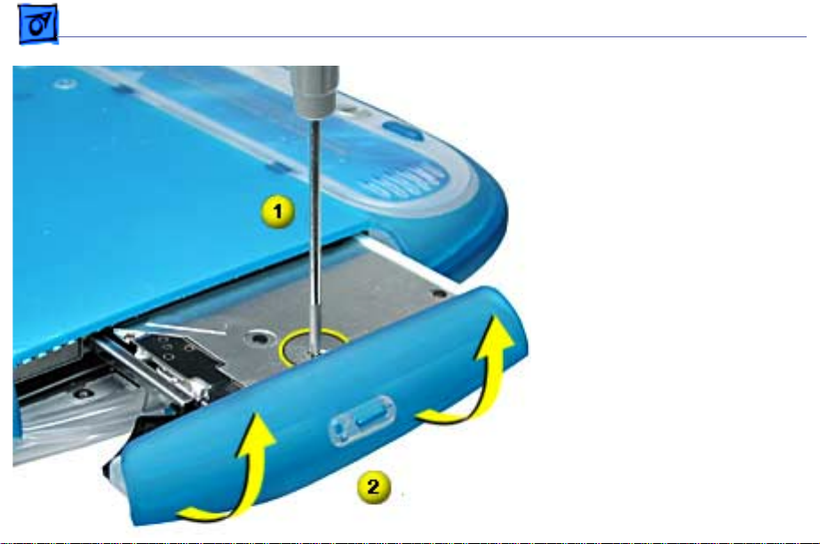
CD-ROM Bezel
Before you begin, remove
the following:
• AC adapter
• Battery
1. Turn the computer over
and press the manual
disc eject button to eject
the CD tray.
2. Use a #0 Phillips
screwdriver to remove
the small screw on the
CD tray near the center
of the bezel.
3. Carefully rotate t
as shown, to remove.
he bezel
Page 7
Take Apart DVD-ROM Bezel - 5
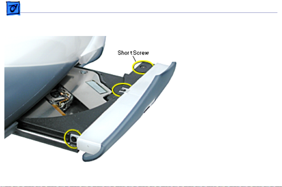
DVD-ROM Bezel
Before you begin, remove
the following:
• AC adapter
• Battery
1. Press the manual disc
eject button to eject the
DVD tray.
2. Use a #0 Phillips
screwdriver to remove
the three small screws
shown here.
Replacement Note:
screw holes strip easily.
Gently tighten the
screws. Do not
overtighten.
The
Page 8
Take Apart DVD-ROM Bezel - 6
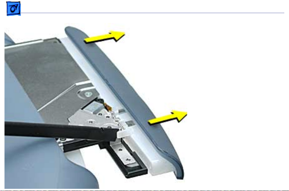
3. Turn the computer over.
4. With a non-marring
flat-blade tool,
carefully push where
shown to release the tab
catch.
5. Carefully pull the bezel
straight off to remove.
Page 9
Take Apart Keyboard and AirPort Card - 7
Keyboard and AirPort Card
Before you begin, remove
the following:
• AC adapter
• Battery
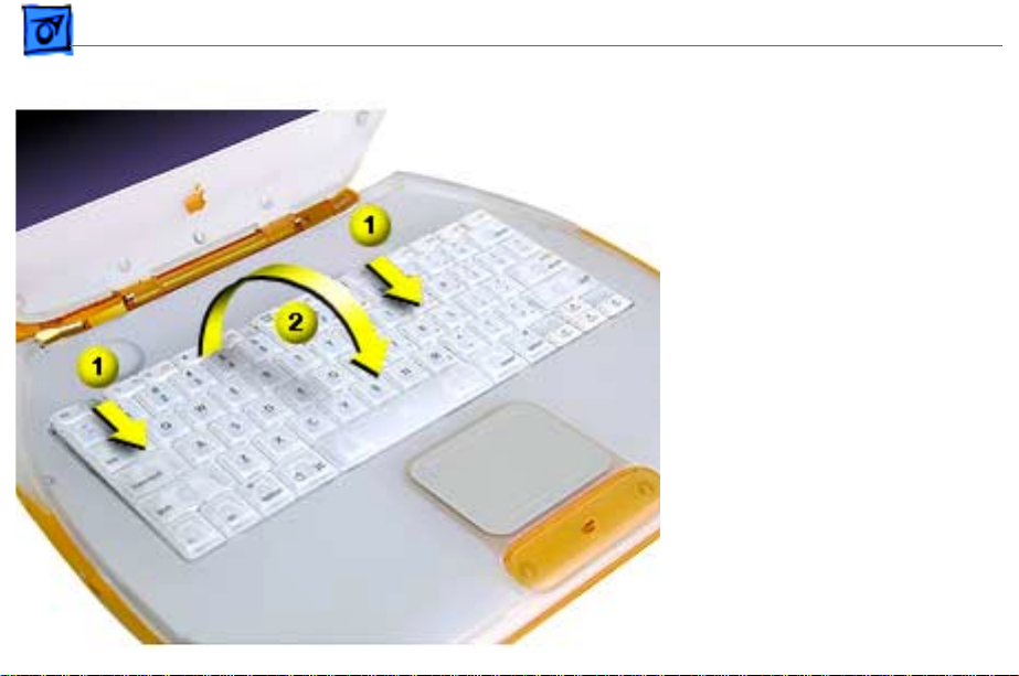
1. Place a cloth on the
palmrest to protect it
from scratches.
2. Locate the two keyboard
release tabs on the
keyboard to the left of
the F1 and F9 keys, and
slide them toward you.
Page 10
Take Apart Keyboard and AirPort Card - 8
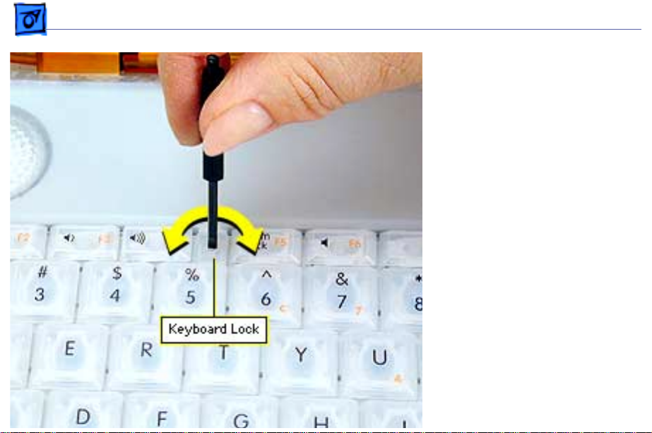
3. If the keyboard does not
pop up, it may be locked.
Locate the keyboard lock
screw (left of the num
lock key) . Turn the lock
a half turn in either
direction until the tab
slides out from under the
top case.
4. When the keyboard pops
up, move it slightly
toward the display to
release the tabs in the
front.
5. Flip the keyboard over
and lay it on top of the
palmrest.
Page 11
Take Apart Keyboard and AirPort Card - 9
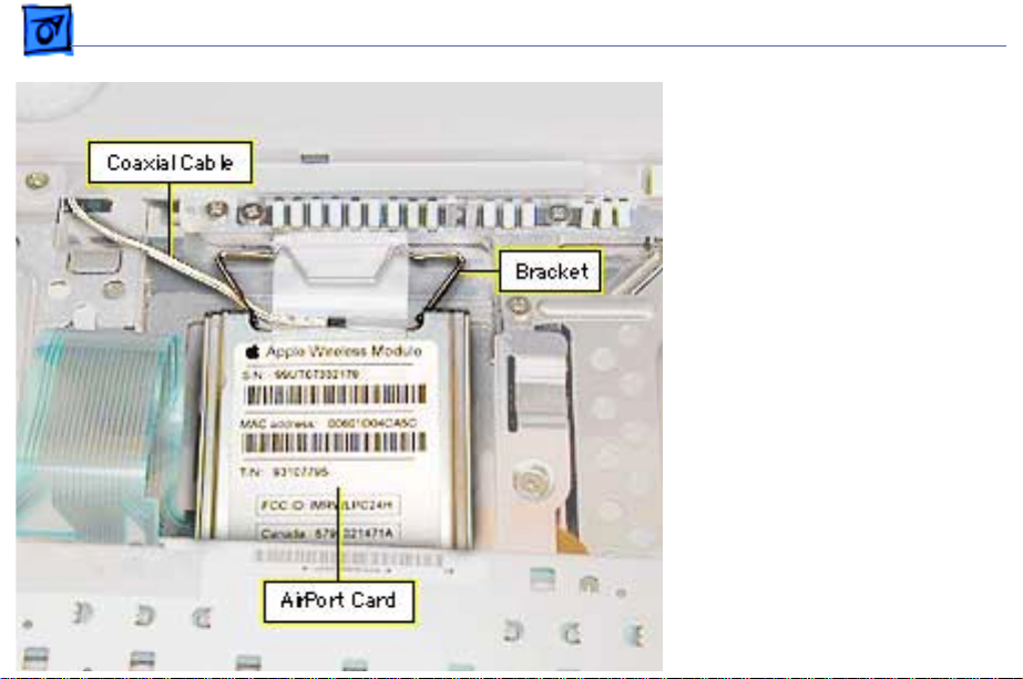
6 Flip up the wire bracket,
and remove the installed
AirPort Card from its
connector. Disconnect the
AirPort antenna coaxial
cable.
Page 12
Take Apart Keyboard and AirPort Card - 10
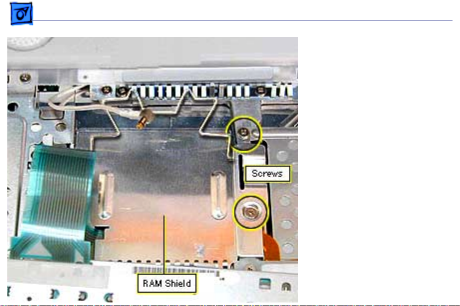
7. Remove the two Phillips
screws on the right side
of the RAM shield.
8. Pull up on the shield and
remove it.
9. Pull up on the keyboard
cable connector loop to
disconnect the keyboard
from the logic board.
Page 13
Take Apart Memory Card (RAM) - 11
Memory Card (RAM)
Before you begin, remove
the following:
• AC adapter
• Battery
• AirPort Card
• RAM shield (see Keyboard
and AirPort Card Take
Apart procedure)
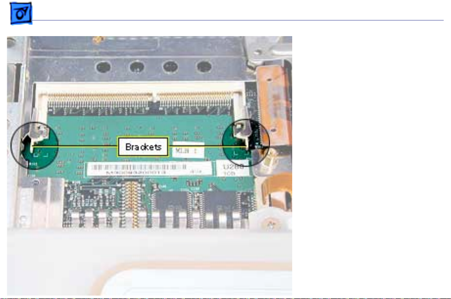
1. If a memory card is in
the memory slot under
the RAM shield,
carefully spread the
brackets apart on each
side of the memory card
until the card releases.
Page 14

Take Apart Memory Card (RAM) - 12
2. Pull the memory card up and out of the memory slot.
3. To install the new memory card, line up the notch in the
card with the small tab in the memory slot. Hold the card
at a 30-degree angle and then push the card into the slot
until it is firmly seated.
4. Then, gently push the card down until the two brackets
on either side of the card lock into place.
Page 15
Take Apart Top Case - 13
Top Case
Before you begin, remove
the following:
• AC adapter
• Battery
• Keyboard
Note:
Use a clean padded
work surface.
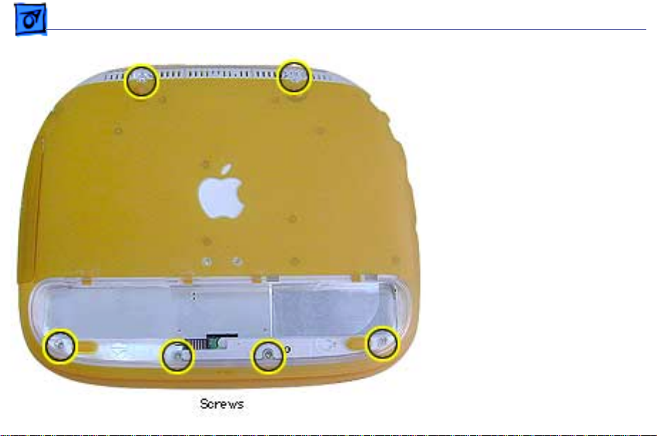
1. Close the display and
turn the computer
upside down.
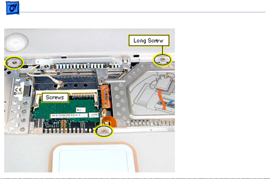
2. R emove the two long T8
screws near the handle.
3. Remove the four shorter
T8 screws in the battery
compartment.
Page 16
Take Apart Top Case - 14
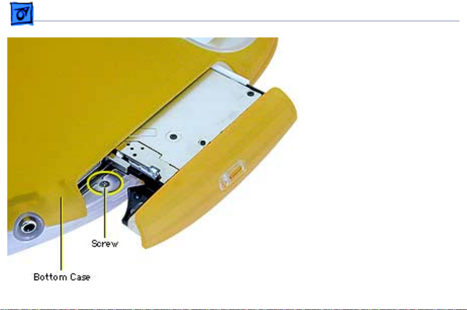
4. Press the manual disc
eject button with the tip
of a jeweler’s
screwdriver or paper
clip to eject the optical
drive tray.
5. Remove the small
Phillips screw in the top
of the drive
compartment.
Page 17
Take Apart Top Case - 15
6. Leave the optical drive
tray partly open and
turn the computer
r ight-side up and open
the display.
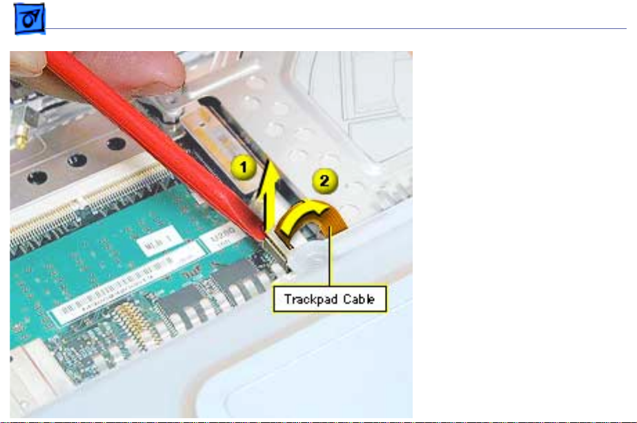
7.
Important:
brackets are extremely
fragile. Do not move
them or place pressure
on them while prying up
the top of the trackpad
connector. Use extreme
care.
Use an ESD-safe flatblade tool (using a
fingernail might also
work) to carefully pry
up the top of the
The side
Page 18
Take Apart Top Case - 16
trackpad cable
connector, only enough
to release the trackpad
cable. Do not remove the
connector.
8. R emove the three
Phillips screws from the
keyboard opening.
Page 19
Take Apart Top Case - 17
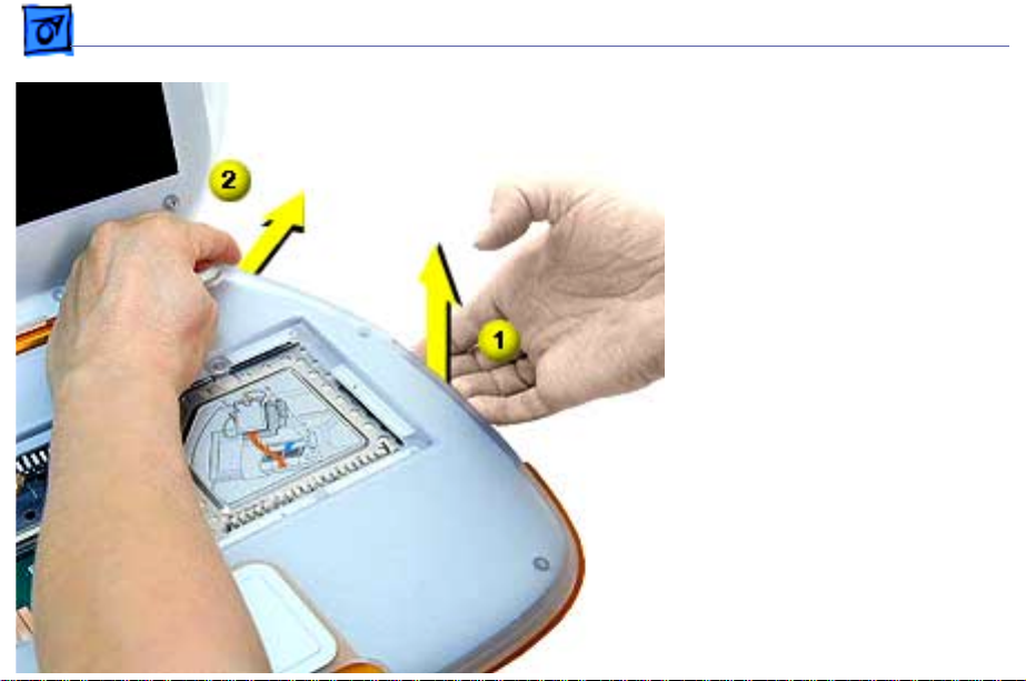
9. With the optical drive
tray open, push up on
the underside of the top
case while pushing out
on the clear lip that
holds the back right edge
of the top case until the
case pops open.
10.Work your fingers along
the back seam and press
out on the clear lip at the
left edge until the top
case pops open.
Page 20
Take Apart Top Case - 18
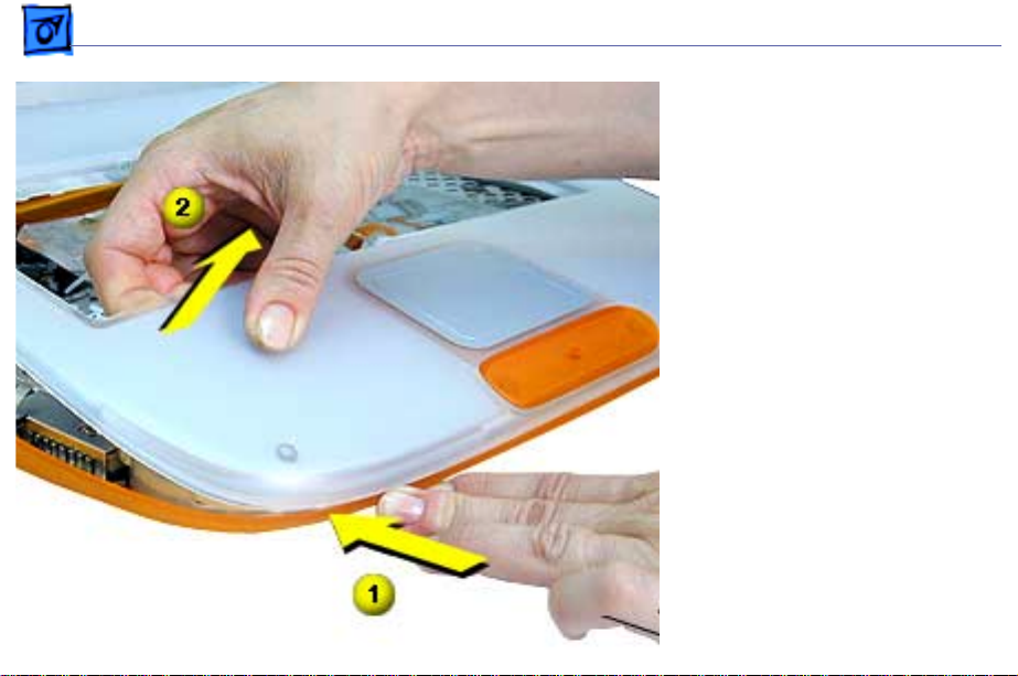
11. At the front left corner,
push in on the bottom
front while pulling up on
the top case.
12.Repeat this process at
the front, right corner.
Important:
top case yet since the
speaker wire is still
connected to it.
Do not remove the
Page 21
Take Apart Top Case - 19
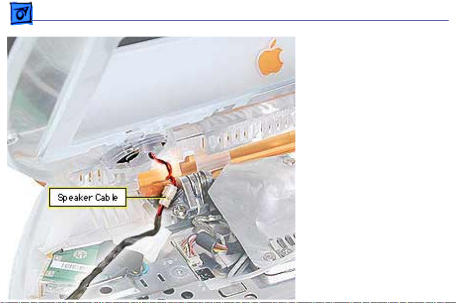
13. Carefully rotate the top
case up and rest it
against the display, then
disconnect the speaker
cable.
Replacement Note:
the speaker cable, then
engage the alignment ridges
on the front of the bottom
case to the front of the top
case first, then lower the
top case. Push firmly on the
top edges of the top case until
they snap into place.
Connect
Page 22
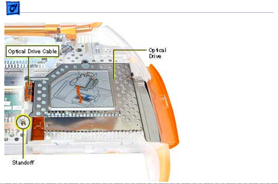
Take Apart Optical Drive - 20
Optical Drive
Before you begin, remove
the following:
• AC adapter
• Battery
• Keyboard
• Top case
1. Disconnect the optical
drive cable from the
logic board.
2. Remove the standoff on
the left side of the
optical drive with a 5
mm nut driver.
Page 23
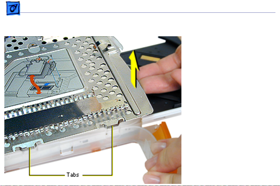
Take Apart Optical Drive - 21
3. Locate the two tabs on
the front side of the
drive carrier. Press on
the plastic below the
tabs and lift up on the
inside of the drive
compartment with your
right hand until the
carrier clears the tabs.
4. With the drive tray still
open, tilt the drive
assembly and lift it out
of the bottom case.
Page 24
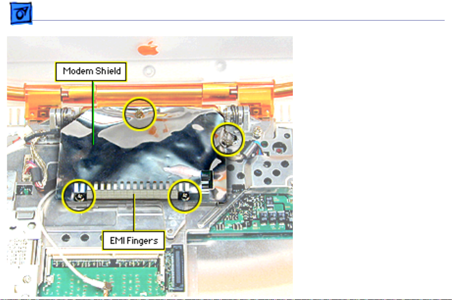
Take Apart Modem - 22
Modem
Before you begin, remove
the following:
• AC adapter
• Battery
• Keyboard
• Top case
Note:
The modem is located
under the foil modem shield.
1. Remove the Phillips
screw holding the back of
the modem shield. This
screw is longer than the
other shield screws.
2. Remove the Ph illips
Page 25

Take Apart Modem - 23
screw holding the right side of the modem shield.
3. R emove the two Phillips screws holding the EMI fingers
to the modem shield and lift the EMI fingers off.
Important:
Replacement Note:
side of the EMI fingers makes contact, through the hole
in the shield, with the metal on the corner of the modem.
4. Peel up the modem shield all around the front and side
edges and push back.
Note:
wider at the left side, has a folded-over tab at the right
back corner that must be peeled back, and has a larger
cut out in front for access to a large Phillips screw that
must be removed before removing the modem.
5. If removing a modem on an iBook (FireWire), remove
Do not pull on the EMI fingers.
Verify that the metal tab on the right
On the iBook (FireWire) the foil EMI shield is
Page 26
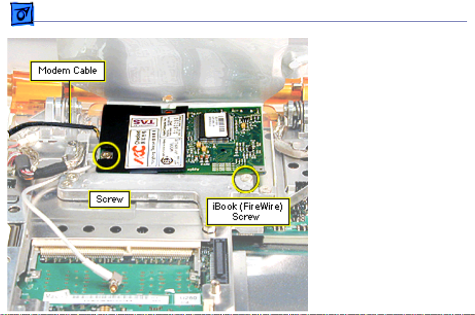
Take Apart Modem - 24
the large Phillips screw
attached to the
computer’s framework
near the right front edge
of the modem.
6. Remove the Phillips
screw on the left side of
the modem board.
7. Check the modem cable
connection to the modem.
If it is not soldered,
disconnect the modem
cable.
8. Lift up on the right side
of the modem to release
it from its connector.
Page 27

Take Apart Modem - 25
RRRReeeeppppllllaaaacccceeeemmmmeeeennnntttt NNNNooootttteeee:::: After replacing an international
modem, use the Modem Country Selector utility to set the
modem to the correct country.
Page 28
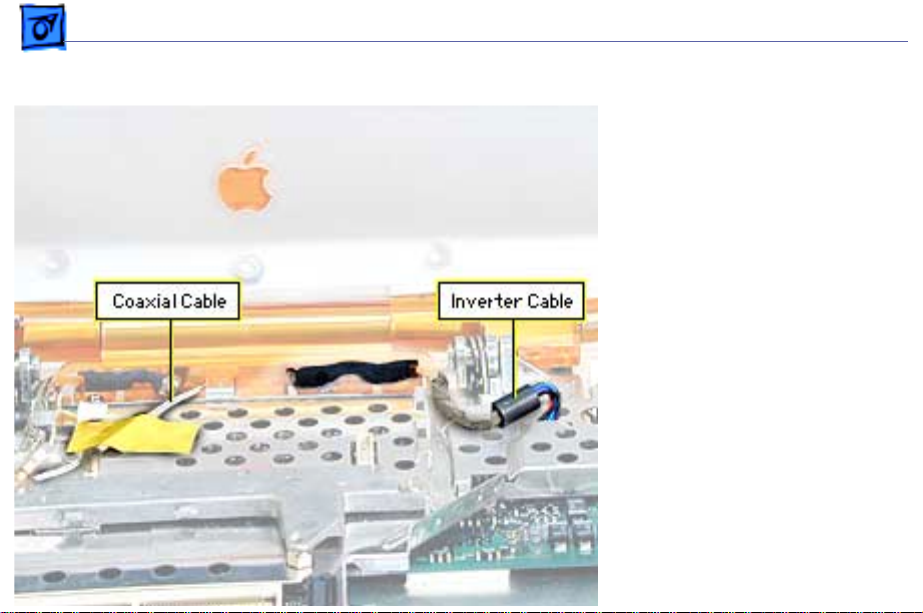
Take Apart Display Assembly - 26
Display Assembly
Before you begin, remove
the following:
• AC adapter
• Battery
• Keyboard
• Top case
• Modem
1. Disconnect the inverter
cable connector from the
logic board and deroute
the cable from the logic
board EMI shield and the
guides on the center
right clutch cover.
2. Remove the tape from
the antenna coaxial cable
Page 29

Take Apart Display Assembly - 27
and deroute the cable
from the Logic board EMI
shield.
Note:
The hard drive area of
the logic board EMI shield is
a convenient place to keep
tape for reuse.
3.
Important:
cable is fragile. Handle
with care.
Use an IC extractor to
remove the display cable
connector located left of
the modem area and
deroute the display cable
from the guides on the
logic board EMI shield
The display
Page 30

Take Apart Display Assembly - 28
and center clutch cover.
4. Remove the three small
Phillips screws holding
the center clutch cover
to the logic board EMI
shield.
5. Support the display with
one hand and remove the
two large Phillips
screws on the clutches.
Replacement Note:
that display cables do not get
pinched under clutch hinges.
Remember to attach the
display cable grounding wire
with the left clutch screw.
Verify
Page 31

Take Apart Display Assembly - 29
6. Move the display
straight back to clear the
two hooks near the
center of the clutch.
Important:
fragile. Use care to avoid
breaking.
Replacement Note:
behind the bottom case, hold
the display upright and
tilted back. Move the display
toward the hooks on the
bottom case and guide the
hooks into the slot of the
center clutch cover so that
the hooks catch on the back
The hooks are
From
Page 32

Take Apart Display Assembly - 30
edge of the cover. Check the back of the computer before
tightening all the screws to see that the hooks are not
sticking out the back of the clutch cover.
If the hooks show, you may be able to carefully flex the
clutch cover with a non-marring flat-blade tool until the
hooks snap into place.
Page 33

Take Apart Logic Board EMI Shield - 31
Logic Board EMI Shield
Before you begin, remove
the following:
• AC adapter
• Battery
• Keyboard
• Top case
• Optical drive
• Modem
• Display assembly
Page 34

Take Apart Logic Board EMI Shield - 32
1. Remove the thin round
head Phillips screw near
the power port.
2. Remove the small
Phillips screw to the left
of the modem area.
Note:
On the iBook
(FireWire) also remove
the screw located near
the hole for the speaker
wire in the EMI shield.
Page 35

Take Apart Logic Board EMI Shield - 33
3. Remove the two Phillips
screws near the front
edge of the logic board
EMI shield near the hard
drive.
4. Remove the tape on the
speaker cable and
deroute the cable.
5. Remove the small
Phillips screw on the
left side of the logic
board EMI shield,
between the Ethernet and
USB ports.
6. Remove the tape on the
cable of the RJ-11 board
and remove the two thin
Page 36

Take Apart Logic Board EMI Shield - 34
Phillips screws. Lift the board out.
Note:
You may need to flex the outer plastic case outward
slightly to clear the RJ-11 board for removal.
7. Lift up on the right side of the logic board EMI shield to
remove it.
Replacement Note:
in the logic board EMI shield that is above the speaker cable
connector.
Verify that the shield’s edges all fit inside the metal lining of
the bottom case.
Route the speaker cable through the hole
Page 37

Take Apart Charger Board - 35
Charger Board
Before you begin, remove
the following:
• AC adapter
• Battery
• Keyboard
• Top case
• Optical drive
• Modem
• Display assembly
• Logic board EMI shield
1. Disconnect the charger
board’s power cable
connector from the logic
board.
Page 38

Take Apart Charger Board - 36
2. Remove the Phillips
screw holding the plastic
trackpad support then
remove the support.
3. Lift the charger board
out of its compartment.
Replacement Note:
that the shield under the
charger board is in place
before installing the charger
board.
Be sure
Page 39

Take Apart DC- I n Board - 37
DC-In Board
Before you begin, remove
the following:
• AC adapter
• Battery
• Keyboard
• Top case
• Optical drive
• Modem
• Display assembly
• Logic board EMI shield
1. Press down gently on the
logic board near the DCin board.
2. Pull up on the left side of
the DC-in board until
Page 40

Take Apart DC- I n Board - 38
the pins are clear of the connector.
Important:
on the board during this procedure.
3. Grasp the board and the plastic bracket below the board
and pull up and out until the entire unit including the
DC-in port comes free.
Note:
release it.
4. Pull the plastic bracket off the DC-in board.
Replacement Note
board so that the bumps on the bottom fit into the
corresponding holes on the logic board.
Be very careful not to bump or bend the pins
Rotating the DC-in port clockwise may help to
: Insert the plastic bracket into the logic
Page 41

Take Apart Hard Drive - 39
Hard Drive
Before you begin, remove
the following:
• AC adapter
• Battery
• Keyboard
• Top case
• Optical drive
• Modem
• Display assembly
• Logic board EMI shield
1. Lift up on the hard drive
cable connector loop
until the connector
disconnects from the
logic board.
Page 42

Take Apart Hard Drive - 40
Important:
up to prevent bending
pins on the logic board.
2. Remove the three 5 mm
standoff screws holding
the hard drive bracket to
the logic board.
3. Lift the hard drive off
the logic board.
4. If the hard drive bracket
remains attached to the
hard drive, carefully
pull it off. It may be held
on with double-sided
tape. The bracket is
fragile; handle it
carefully.
Pull straight
Page 43

Take Apart Hard Drive - 41
Replacement Note:
will only connect to the hard drive one way. Fit the cable to
the hard drive first to make sure you have the cable installed
correctly.
Connect the hard drive cable to the logic board and then
replace the standoff screws.
The hard drive cable is keyed so that it
Page 44

Take Apart Logic Board - 42
Logic Board
Before you begin, remove
the following:
• AC adapter
• Battery
• Keyboard
• Memory card (if any)
• Top case
• Optical drive
• Modem
• Display assembly
• Logic board EMI shield
• Hard drive
• DC-in board
1. Disconnect the charger
board cable connector
from the logic board.
Page 45

Take Apart Logic Board - 43
2. Remove the standoff
screw above the optical
drive area [1].
3. R emove the standoff
screw at the corner of
the optical drive cut-out
on the logic board [2].
4. R emove the standoff
screw to the right of the
modem connector [3].
5. Remove the standoff
screw near the left
clutch notch [4].
6.
Remove the Phillips screw
below the left side of the
memory card slot [5].
7. Lift the logic board out.
Page 46

Take Apart Sound or Sound/Video Board - 44
Sound or Sound/Video Board
Before you begin, remove
the following:
• AC adapter
• Battery
• Keyboard
• Top case
• Optical drive
• Modem
• Display assembly
• Logic board EMI shield
1. On the iBook, remove the
4 mm nut on the sound
board.
Page 47

Take Apart Sound or Sound/Video Board - 45
On the iBook (FireWire), remove the 5mm nut on the
video/sound board.
2. Lift up on the right end of the board to release it from its
connector, then tilt the board and slide it out of the port
opening.
Page 48

Take Apart Displays - 46
Displays
Display assemblies for the iBook are manufactured by
several different companies. The procedures that follow are
for the IBM display. Take Apart procedures can vary for
different manufacturers’ displays.
Use the correct replacement part for the display that you
are replacing. Manufacturer-specific parts include the
following: display, display cable, EMI shield and mounting
frame.
Page 49

Take Apart Display Bezel - 47
Display Bezel
Before you begin, remove
the following:
• AC adapter
• Battery
1. R emove the two long T8
screws on the bottom
front of the bezel.
Page 50

Take Apart Display Bezel - 48
2. Turn the display face
down and remove the two
short T8 screws on the
rear cover inside the
handle.
3. Open the handle and pull
the rear cover and shield
off.
Replacement Note:
a cosmetic shield under the
rear cover. Be sure it is in
place before continuing.
There is
Page 51

Take Apart Display Bezel - 49
4. Turn the display over so
the screen faces up.
5. P ush up on the bezel
from inside the handle
area until the bezel and
display housing pops
apart.
6. Use the same procedure
to separate the other
bottom corner.
Page 52

Take Apart Display Bezel - 50
7. Work your hands around
each side, separating the
bezel from the display
housing. At the top
corners, pull the plastic
of the display housing
out while pulling up on
the bezel.
Important:
glue (double-stick tape)
along the bottom of the
display that adheres to
the cosmetic metal on the
inside of the bezel, use
care when removing to
avoid damage to the
metal.
If there is
Page 53

Take Apart Display (IBM) - 51
Display (IBM)
Before you begin, remove
the following:
• AC adapter
• Battery
• Keyboard
• Top case
• Modem
• Display assembly
• Display bezel
1. Remove any tape from
the bulb wire connection
sleeve.
2. Pull the connection
sleeve out and slide it
toward you to expose the
Page 54

Take Apart Display (IBM) - 52
connector. Remove any
tape on the connector,
then disconnect the bulb
wire connector (from
the inverter board
connector).
3. Deroute the cables from
the center clutch cover.
4. Tilt the center clutch
cover and remove it.
5. Lift up the back of the
display until the center
left and right clutch
covers are visible.
Page 55

Take Apart Display (IBM) - 53
6. Remove the screw on the
back of the center left
clutch cover.
Page 56

Take Apart Display (IBM) - 54
7. Slide the center left
clutch cover along the
cable until you can
remove it from the
cable.
8. R emove the grounding
strap, if any, attached to
the display frame from
this cable.
Page 57

Take Apart Display (IBM) - 55
9. R emove the four Phillips
screws on the corners of
the display.
10. Remove the display.
Replacement Note:
the inner metal shield from
the center left clutch cover
and replace it first. Then
slide the plastic cover over
it.
Separate
Page 58

Take Apart Inverter Board - 56
Inverter Board
Before you begin, remove
the following:
• AC adapter
• Battery
• Keyboard
• Top case
• Modem
• Display assembly
• Display bezel
Note:
It is not necessary to
remove the display
completely.
1. Remove the four Phillips
screws on the corners of
the display.
Page 59

Take Apart Inverter Board - 57
2. Remove any tape from
the bulb wire connection
sleeve.
3. Pull the connection
sleeve out and slide it
toward you to expose the
connector. Remove any
tape on the connector,
then disconnect the bulb
wire connector (from
the inverter board
connector).
4. Place a protective paper
or cloth over the clutch,
then tilt the display and
the shield forward and
rest them on the
clutches.
Page 60

Take Apart Inverter Board - 58
5. Disconnect the inverter
board/sleep LED cable
from the inverter board.
6. Remove the three
Phillips screws from the
inverter board and
remove the board.
Page 61

Take Apart Wireless Antenna - 59
Wireless Antenna
Before you begin, remove
the following:
• AC adapter
• Battery
• Keyboard
• Top case
• Modem
• Display assembly
• Display bezel
• Display
• Inverter board
1. Loosen the four short
Phillips screws on the
top of the display
mounting frame.
Page 62

Take Apart Wireless Antenna - 60
2. Remove the four long Phillips screws on the bottom of
the display mounting frame (three, if a grounding screw
was removed when removing the display).
3. Pull up on the ends of the antennas to remove them from
the display housing. The antennas fit in grooves and are
held in place with adhesive.
4. Lift up on the bottom of the display mounting frame and
slide it toward the handle.
5. Lift the mounting frame out.
6. Deroute the antenna from the display frame.
7. Remove the two screws from the antenna IC board.
Replacement Note:
bottom left inverter board screw tab on the mounting frame
and will contact the metal of the display housing.
Verify that the EMI spring is slid onto the
Page 63

Take Apart Handle - 61
Handle
Before you begin, remove
the following:
• AC adapter
• Battery
• Keyboard
• Top case
• Modem
• Display assembly
• Display bezel
1. Deroute the cables from
the center clutch cover.
2. Tilt the center clutch
cover and remove it.
Page 64

Take Apart Handle - 62
3. Lift up the back of the
display until the screws
on the back of the center
left and right clutch
covers are visible.
Remove the screws.
4. Slide the clutch covers
and their metal sleeves
off of the clutches.
5. Deroute the cables off of
the clutches.
Page 65

Take Apart Handle - 63
6. Loosen the four short
Phillips screws on the
top of the display
mounting frame.
7. Remove the four long
Phillips screws on the
bottom of the display
mounting frame.
Page 66

Take Apart Handle - 64
8. Remove the four
exterior screws on the
display housing.
Important:
have a cosmetic finish.
Keep them separate from
other screws.
9. Slide the display toward
you, then lift up on the
bottom of the display and
remove the handle and
clutch assembly.
10. Pull the clutches off the
handle.
These screws
Page 67

Take Apart Handle - 65
Handle Replacement
Important:
clutches have unique
springs.
1. Fit a spring onto a
spring shaft so the
cross-wire on the end of
the spring slides into the
slot in the end of the
spring shaft.
2. Insert the spring
assembly into the
appropriate handle end.
3. Position the handle so
that the holes in the
handle plastic face up
The left and right
Page 68

Take Apart Handle - 66
Spring tension adjustment
Play Movie
and the handle ends are closest to you.
4. Lay the clutch for this side of the handle, in the open
position, on the handle in its approximate position.
5. From above the handle, position a very thin needle nose
pliers so that its handle is up and the nose points down.
6. Firmly grab the flat sides on the end of the spring shaft;
leave enough room on the end so that the clutch can be put
onto it slightly, as the clutch will be used to hold the
tension on the spring while repositioning the pliers.
Rotate the pliers handle toward you and around,
approximately 180 degrees, while verifying that the
shaft stays flush against the handle. Then slide the clutch
onto the end of the spring shaft to hold it securely from
turning.
7. Remove the pliers, then firmly reposition the pliers as
before and hold the spring shaft from turning. Remove
Page 69

Take Apart Handle - 67
the clutch, turn the pliers another 180 degrees (for a
total of 360 degrees), then slide the clutch all the way
onto the spring shaft as you remove the pliers.
8. Temporarily secure the clutch and handle end assembly
with tape to prevent it from sliding apart.
9. Repeat the procedure for the other side of the handle.
10. Place the clutches on the handle assembly under the
bottom of the display frame so that the pins in the
clutches align with the pin holes in the display frame.
Secure the clutches to the frame with screws. Make sure
to attach any grounding strap under the appropriate
screw.
Important:
the display frame and clutch assembly.
11.Remove any tape used to secure the handle and clutches.
Verify that the cables are not caught between
Page 70

Take Apart Handle - 68
12.Slide the top of the display frame into the slots at the top
of the display housing.
Important:
13. Attach the exterior screws.
Verify alignment of the antenna cable.
Page 71

K
Service Source
Exploded V ie ws
iBook / iBook (FireWire)
© 2002 Apple Computer, Inc. All rights reserved.
Page 72

Exploded View CPU Case - 1
iBook CPU Case Exploded View
CPU Case
and Screw Locator
Note:
Circled numbers indicate which screw is used at that locaton and correspond
to the screws on the iBook Screw Reference Sheet.
RJ-11Board &
Modem Cable
Speaker Cable
5
Hard
Drive
Bracket
18
Hard Drive
Hard Drive
Cable
Sound or
Sound/Video
Board
Trackpad
Button
Support
9
2
22
21
Keyboard
5
10
5
18
15
18
7
11
9
9
5
5
6
5
16
13
9
RAM Card Shield
6
14
5
6
5
5
20
19
18
17
2
10
10
13
6
Wireless Card
14
Rear Cover
& Shield
Top Housing
EMI Fingers
Modem
EMI shield
Modem
Stiffener Brace
Logic Board Brace
& EMI Shield
CD-ROM Drive
5
CD Bezel
23
1
23
RAM Card
DC-In Board
DC-In Board
Bracket
Logic Board
Left Clutch Cover
& Shield
Center Clutch Cover
& Shield
Right Clutch Cover
& Shield
Bottom Housing
Spring Plate
EMI Fingers
Charger Board
Charger Board
Cosmetic Shield
24
DVD
Bezel
Lithium Ion
Battery
Battery Door
Page 73

Exploded View Display Case - 2
iBook Display Case Exploded View
Display Case
and Screw Locator
Note:
Circled numbers indicate which screw is used at that locaton and correspond
to the screws on the iBook Screw Reference Sheet.
Wireless Board
& Antenna Cable
Display Mounting Frame
3
3
3
7
7
3
3
3
13
3
3
3
3
3
3
Display EMI Shield
8
8
3
7
7
3
Left Handle Spring
& Spring Shaft
Inverter Board
Inverter Board Cable
& Sleep LED Board
Display Housing
8
8
12
Left
Clutch
4
4
Right Handle Spring
& Spring Shaft
Center Left
Clutch Cover
& Shield
Center Right
Clutch Cover
& Shield
12
Right
Clutch
Handle
Display Bezel
13
Display
Page 74

Exploded View Screw Reference Sheet - 3
SCREW
DIMENSIONS (MM)
Length
1
922-5396
2
922-5377
3
922-5378
4
5
922-5380
6
922-5382
922-5383
7
8
922-5376
9
922-5391
922-5394
10
11
922-5371
11
12
922-5372
13
922-5392
14
922-5393
922-5410
15
16
922-5412
17
922-5411
18
922-5408
19
922-5409
iBook Screw Reference Sheet
HEX
DIMENSIONS (MM)
Length
Screw Reference Sheet
Note:
The circled numbers in front of each screw description correspond
to the screw location in the Exploded View diagrams.
The number in parenthesis at the end of the screw's description
indicates the quantity used at that location.
4.5 mm Phillips CD-ROM Drive Bezel (1)
(black)
3 mm Phillips Center clutch cover (3)
Logic board EMI shield by USB port (1)
2.7 mm Phillips Display bracket corners (4)
Display mounting frame, top (4)
Sleep LED board (2)
Wireless antenna board (2)
Inverter board (3)
3 mm Phillips Center right/left clutch covers (2)
(thin head)
4 mm Phillips Top case (3)
Top case inside CD tray (1)
Modem EMI shield, right (1)
Modem EMI fingers (2)
Logic board EMI shield by modem (1)
Logic board EMI shield by hard drive (2)
5 mm Phillips RAM shield (2)
Modem EMI shield, top (1)
Modem (1)
5 mm Phillips Logic board by RAM card (1)
(with patchlock) Display mounting frame, bottom (4)
5 mm Phillips Clutch to display (white zinc finish) (4)
6 mm Torx T-8 Bottom case under battery door (4)
7 mm Phillips Logic board EMI shield near power port (1)
RJ-11 board (2)
7 mm Phillips Charger board trackpad support (1) — iBook (original)
5 mm Phillips Charger board trackpad support (1) — iBook (FireWire)
10 mm Phillips Clutch to logic board shield (2)
13 mm Torx T-8 Bottom case by handle (2)
Display bezel (2)
4.5 mm Torx T-8 Display rear door (2)
5x5 mm Hex CD to logic board shield (1)
5x4.5 mm Hex Logic board left of modem (1)
5x6.3 mm Hex Logic board right of modem (1)
5x8 mm Hex Hard drive to logic board (3)
Logic board left of CD (1)
5x9 mm Hex Logic board above CD (1)
20
922-5385
21
922-5417
21
22
23
24
4.5 mm Phillips Stiffener brace, bottom right (1) — iBook (FireWire)
4 mm Hex nut Sound board (1) — iBook (original)
5 mm Hex nut Sound/video board (1) — iBook (FireWire)
2.7 mm Phillips Logic board EMI shield by speaker cable hole (1) — iBook (FireWire)
3.2 mm Phillips DVD-ROM bezel (2)
(black)
2 mm Phillips DVD-ROM bezel (1)
(black)
Page 75

K
Service Source
Troubleshooting
iBook / iBook (FireWire)
© 2002 Apple Computer, Inc. All rights reserved.
Page 76

Troubleshooting Power Issues / Sleep - 1
Power Issues
Warning:
±
system down before changing the battery, or make sure an AC
power adapter is connected. Changing the battery while the system
is in sleep mode, without a power adapter, will result in a loss of
all data stored in RAM.
The iBook has no backup battery. Therefore, shut the
Sleep
There is an option in the Energy Saver control panel called
“Preserve memory contents on sleep.” When this option is
selected, the system creates a file containing all the information
contained in RAM at that time, and stores it on the hard disk before
going into sleep mode.
Battery Verification
When the power adapter is being used, the ring around the power
adapter port glows green when the battery is fully charged. The
ring glows amber if the battery is being charged.
You can also check the battery status by looking at the Battery
portion of the control strip or the battery symbol in the upper
right corner of the Finder menu bar.
Power Adapter Verification
Try using a known-good power adapter if the computer cannot run
off the existing one, or try the existing power adapter with
another iBook or G3 Series PowerBook
Under normal operation, the ring around the power adapter port
will glow green or amber if the computer is receiving adequate
power.
Power Manager Reset
±
Warning:
removes a RAM disk. Resetting the power manager also resets the
date and time.
iBook computers have a reset button on the keyboard above the
power button. Press the button once with a paper clip to reset the
power manager. Make sure the button clears the plastic of the top
case when you release it, and is not stuck in the down position.
Resetting the power manager permanently erases and
Page 77

Troubleshooting Power Issues / PRAM Reset - 2
PRAM Reset
Warning:
±
if you do not have “Save on Shutdown” selected in the Memory
control panel. Resetting PRAM also restores default settings, such
as Time Zone and Daylight Savings Time settings, in some control
panels, so note custom settings before you reset PRAM.
• Turn on the computer by pressing the power button.
• Immediately hold the Option-Command-P-R keys.
• Hold down the keys until you hear the startup chime at least
one additional time after the initial startup chime.
Resetting PRAM erases the contents of the RAM disk
Page 78

Troubleshooting Block Diagrams / iBook - 3
Block Diagrams
iBook
This is a simplified block diagram of the iBook. The diagram shows
the main ICs and the buses that connect them.
512 KB
backside
L2 cache
ATI Rage
Mobility-L
graphics IC
Flat-panel
display
Wireless
LAN
(optional)
AGP bus
Power PC
G3
micro-
processor
60x bus
UniNorth
memory
controller
and PCI
bus bridge
PCI
bus
Memory
bus
Boot
ROM
Ultra A T A bus
SDRAM
SO-DIMM
(optional)
32 MB
SDRAM
PHY
Hard
disk
drive
Ethernet
port
CD-ROM
PMU99
power
controller
Trackpad
ATA bus
KeyLargo
I/O device
and disk
controller
Keyboard
Power supply
and charger
Micronas
codec
Modem
Internal
speaker
Headphone
jack
Modem
connector
USB port
Page 79

Troubleshooting Block Diagrams / iBook (FireWire) - 4
iBook (FireWire)
This is a simplified block diagram of the iBook (FireWire). The
diagram shows the main ICs and the buses that connect them.
PowerPC 750CX
microprocessor
(has 256K 1:1
L2 cache)
60x bus
Flat-panel
display
SDRAM
SO-DIMM
(optional)
64 MB
SDRAM
Wireless
LAN
(optional)
CD-ROM
or
DVD-ROM
PMU99
power
controller
Memory
ATA bus
bus
UniNorth
memory
controller
and PCI
bus bridge
PCI
bus
KeyLargo
I/O device
and disk
controller
AGP 2X bus
Firewire
PHY
Ethernet
PHY
Boot
ROM
Ultra ATA bus
ATI Rage
M128
graphics IC
Hard
disk
drive
Micronas
codec
Modem
Firewire
port
Ethernet
port
A/V jack
Internal
speaker
Modem
connector
USB port
Trackpad
Keyboard
Power supply
and charger
Page 80

Troubleshooting Symptom Charts / How to Use the Symptom Charts - 5
Symptom Charts
How to Use the Symptom Charts
The Symptom Charts included in this chapter will help you
diagnose specific symptoms related to the product.
The steps to solve a symptom are listed sequentially. You might not
need to perform every step before the symptom is solved. Start
with the first step, and then test for the symptom. If the symptom
persists, replace any modules you removed, go to the next step,
and test again. Continue down the list until the symptom is solved.
AirPort Card
AirPort Card not
recognized
Drive does not accept
disc (mechanical
failure)
Disc icon does not
show up on desktop,
or dialog box appears
to initialize disc
1 Use Software Update control panel or see the Apple Software
Updates web page to make sure the latest version of AirPort
software is installed.
2 Boot using Mac OS All extensions setting.
3 Reseat AirPort Card.
4 Remove and reinstall the AirPort software.
5 Replace with known-good AirPort Card.
6 Replace logic board.
CD-ROM Drive
1 Verify disc is properly seated in the carrier.
2 Replace drive.
3 Replace logic board.
1 Verify disc is not a DVD-ROM or DVD-RAM disc.
2 Check that the correct software extensions are loaded.
3 Replace disc (if dirty or damaged).
4 Verify the CD cable is firmly connected to the logic board.
Drive does not accept
disc (mechanical
failure)
Disc icon does not
show up on desktop,
or dialog box appears
to initialize disc
DVD-ROM Drive
1 Verify disc is properly seated in the carrier.
2 Replace drive.
3 Replace logic board.
1 Check that the correct software extensions are loaded.
2 Replace disc (if dirty or damaged).
3 Verify the DVD cable is firmly connected to the logic board.
Page 81

Troubleshooting Symptom Charts / Error Beeps - 6
Error Beeps
The computer automatically performs a power-on self test when
it is turned on after being fully shut down (not a restart). This
section describes what to do if beeps are heard during the startup.
Note:
The iBook and iBook (FireWire) have one memory
expansion slot. Refer to the Memory Replacement instructions for
removal and installation.
Computer beeps once
at startup
Computer beeps twice
at startup
Computer beeps three
times at startup
Computer beeps four
times at startup
1 One beep means that no RAM is detected.
2 If a RAM card is installed in the expansion slot, remove it and
put in known-good and compatible RAM and restart.
• If symptom does NOT repeat, replace RAM card.
• If symptom repeats, replace logic board.
3 If no RAM card is installed, replace logic board.
1 Two beeps means that EDO memory is installed in the
expansion slot. The iBook does not accept EDO memory.
2 Replace RAM card with known-good and compatible RAM and
restart.
• If symptom repeats, replace logic board.
1 Three beeps means that no RAM banks passed memory testing.
2 If a RAM card is installed in the expansion slot, remove it and
put in known-good and compatible RAM and restart.
• If symptom does NOT repeat, replace RAM card.
• If symptom repeats, replace logic board.
3 If no RAM card is installed, replace logic board.
1 Four beeps indicates a bad checksum for the remainder of the
boot ROM. The ROM (which is located on the logic board) is
bad.
2 If a RAM card is installed in the expansion slot, remove it and
put in known-good and compatible RAM and restart.
• If symptom does NOT repeat, replace RAM card.
• If symptom repeats, replace logic board.
3 If no RAM card is installed, replace logic board.
Related articles:
58442: Power On Self-Test Beep Definition - Part 2
Page 82

Troubleshooting Symptom Charts / Hard Drive - 7
Hard Drive
Internal hard drive
does not spin
No response from any
key on keyboard
1 Make sure power adapter is connected.
2 Disconnect external USB devices.
3 Verify Drive Setup does not see the hard drive.
4 Check hard drive connection.
Pull up evenly on the cable to
5 Replace hard drive cable.
avoid bending pins.
6 Replace hard drive.
7 Replace logic board.
Note:
Keyboard and Trackpad
1 Verify that computer is on.
2 Reset the power manager by pressing the reset button above
the power button. Wait five seconds and press the power
Before continuing, make sure the reset button
button.
is not caught under the plastic of the top case.
3 Boot from the system software CD.
4 Check keyboard connection by disconnecting and reconnecting
the keyboard cable.
5 Replace keyboard.
6 Replace logic board.
Note:
Cursor does not move
when you are using
trackpad
Cursor moves on
screen with external
mouse connected, but
clicking or doubleclicking the mouse
has no effect
1 Verify that no USB device is connected.
2 Reset power manager and boot from startup CD. (Reset the
power manager by pressing the reset button above the power
button. Wait five seconds and press the power button.
Before continuing, make sure the reset button is not caught
under the plastic of the top case.)
3 Check trackpad connection to the logic board.
trackpad does
4 Connect USB mouse and try to move cursor. If
not move cursor but external USB mouse does, replace
trackpad (included in top case).
5 Replace logic board.
1 If the mouse is connected to an external USB keyboard,
connect the mouse to the USB port on the computer.
2 Try an Apple mouse with no other USB devices connected.
3 Boot off the CD that came with the computer. If the mouse
works, perform a clean installation of the system software.
Note:
Page 83

Troubleshooting Symptom Charts / Keyboard and Trackpad - 8
Cursor moves, but
clicking trackpad
button has no effect
Cursor does not move
on the screen with an
external mouse, but
USB external
keyboard works
1 Reset the power manager by pressing the reset button above
the power button. Wait five seconds and press the power
Before continuing, make sure the reset button
button.
Note:
is not caught under the plastic of the top case.
2 Remove top case and manually press trackpad button on
charging board with a nylon tool or other non-metal object. If
button activates cursor, check top case seating.
3 Verify the charging board is connected to the logic board.
4 Replace charging board.
5 Replace trackpad button actuator (included in the top case).
1 Verify that the mouse is connected securely to the USB
keyboard or port.
2 Check inside mouse for buildup of dirt or other contaminants.
Clean mouse if necessary.
3 Start up from the system software CD to see if the problem is
software.
4 If mouse is connected to the keyboard, connect it to a USB
port.
5 Try another mouse.
6 Replace logic board.
Cursor intermittently
does not move or
moves erratically
Note:
User must touch trackpad with the surface of only one
finger at a time and point directly down on the trackpad surface.
1 Clean trackpad surface (with computer off, using a non-
static-inducing material).
2 Reset the power manager by pressing the reset button above
the power button. Wait five seconds and press the power
Note:
button.
Before continuing, make sure the reset button
is not caught under the plastic of the top case.
3 Try the computer on battery power. If problem goes away,
replace power adapter.
4 Boot from the system software CD to see if the problem is
software.
5 Check trackpad connection to the logic board.
6 Replace trackpad (included in top case).
7 Replace logic board.
Page 84

Troubleshooting Symptom Charts / Modem - 9
Modem
No dial tone 1 Verify known-good analog (not digital) telephone line.
2 Verify known-good RJ11 telephone cable.
3 Verify RJ11 cable is not plugged into Ethernet port.
4 Inspect RJ11 connector and modem port for pin damage.
5 Verify RJ11 telephone cable is firmly installed in the modem
port.
6 If using Apple Remote Access 3.0, select Ignore Dial Tone in
the Modem control panel. If the modem connects with this
setting selected, try another phone line. If using a terminal
or communications program, enter atx1 to disable tone
detection. To reset the modem back to the factory settings,
enter atz.
7 Verify cable connector from RJ-11 board is plugged into
modem correctly.
8 Replace the RJ-11 board and connector cable.
9 Replace modem.
No internal modem
selection available
Modem reports an
error when dialing
out
Modem is having
trouble connecting to
Online site
1 Verify modem is properly installed and plugged in.
2 Verify correct modem software is installed and selected.
3 Reset PRAM and perform a clean installation of system
software. To reset PRAM, press the power button, then hold
down the Option-Command-P-R keys until you hear the
startup chime at least one additional time after the initial
startup chime.
4 Replace modem.
1 Use the Modem Country Selector utility to make sure the
modem is set to the correct country.
2 Make sure the correct driver is installed and the correct CCL
is selected and that they are not corrupted. If necessary,
reinstall the driver and/or CCL.
3 Try another cable and phone jack.
4 If problem persists, reinstall system and modem software.
1 Use the Modem Country Selector utility to make sure the
modem is set to the correct country.
2 The phone line may have too much noise. If the user has a
second line, try that one. The user should contact their local
phone company and request their line be checked.
3 Check to make sure the TCP/IP control panel is correctly
configured for the user's Internet Service Provider. If the
TCP/IP control panel is not configured correctly, it may
connect but won’t be able to access any sites.
4 Sometimes online services use different servers for dial-up/
Page 85

Troubleshooting Symptom Charts / Power - 10
authentication and for services. If one server is down, users
may be able to log on but not access any services. Contact the
online service for help.
The dialup software
will not initiate a
connection
Modem is dropping its
connection
1 Use the Modem Country Selector utility to make sure the
modem is set to the correct country.
2 Make sure dialup software is fully installed and all required
extensions are enabled. If necessary, reinstall the dialup
software and provide the necessary information for setup.
1 Use the Modem Country Selector utility to make sure the
modem is set to the correct country.
2 Try another cable and phone jack.
3 The phone line may be too noisy to handle the higher modem
speeds. Try connecting at a slower speed or use a generic CCL
file. (If you are familiar with the CCL script language, you
can edit the modem script to force a connection at a lower
speed.) If the problem continues, contact the phone company
to report the bad phone line.
4 Verify that the user has call waiting on that phone line. With
call waiting active, an incoming call can interrupt the
connection. Disable call waiting using AT commands placed in
the init string of the dialup application. Usually the string is
*70.
5 There may be a problem with the server to which you are
connecting. Servers sometimes develop problems that
disconnect users without explanation. Try calling back later
or use an alternate number if one is available.
6 Check with the Internet Service Provider.
7 Reseat the modem. If the problem persists, replace the
modem.
Power
Computer won’t start up1 Reset the power manager by pressing the reset button above
the power button. Wait five seconds and press the power
Note:
button.
is not caught under the plastic of the top case.
2 Try known-good power adapter.
3 Remove battery.
4 Disconnect internal keyboard completely and try starting up
the computer. If the computer starts up, replace keyboard.
5 Remove any additional RAM and AirPort Card.
6 Replace DC-in board
7 Replace logic board.
Before continuing, make sure the reset button
Page 86

Troubleshooting Symptom Charts / Power - 11
Computer runs when
plugged into power
outlet but not on
battery power
Computer runs with
battery, but not with
the power adapter
plugged into power
outlet
1 Turn off the computer, then reset the power manager by
pressing the reset button above the power button. Wait five
Before continuing,
seconds and press the power button.
Note:
make sure the reset button is not caught under the plastic of
the top case.
2 Reseat battery to make sure battery is mating with contacts
on logic board.
3 Try known-good, firmly seated, charged battery. Repeat once.
4 Replace charging board.
5 Replace logic board.
1 Reset the power manager by pressing the reset button above
the power button. Wait five seconds and press the power
Before continuing, make sure the reset button
button.
Note:
is not caught under the plastic of the top case.
2 Try a known-good power adapter.
3 Check lights around power port to see if they glow amber or
green.
4 Replace DC-in board.
5 Replace logic board.
Screen is blank;
backlight isn’t on;
computer doesn’t
respond
Power adapter is
plugged in, but
Control Strip doesn’t
indicate adapter is
connected
1 Reset the computer by holding the Command-Control-power
button simultaneously.
2 Reset the power manager by pressing the reset button above
the power button. Wait five seconds and press the power
Note:
button.
Before continuing, make sure the reset button
is not caught under the plastic of the top case.
3 Check power adapter cable.
4 Try known–good, charged battery.
5 Try known-good power adapter.
6 Reset PRAM. Press the power button, then hold down the
Option-Command-P-R keys until you hear the startup chime
at least one additional time after the initial startup chime.
7 Check inverter and display cable connections to the logic
board.
8 Remove keyboard and additional memory (if installed) and
restart computer.
9 Replace logic board.
1 Verify that power adapter is connected correctly and the
power cord is plugged solidly in the adapter.
2 Verify that there is power at the outlet.
3 Try known-good power adapter (45 watt).
4 Try known-good power cord.
5 Reset the power manager by pressing the reset button above
the power button. Wait five seconds and press the power
Page 87

Troubleshooting Symptom Charts / Sound - 1 2
button.
is not caught under the plastic of the top case.
6 Replace DC-in board.
7 Replace logic board.
Battery won’t charge 1 Turn off the computer and press the reset button above the
power button. Wait five seconds and press the power button.
2 Insert battery, leave in 15 seconds, then remove it. Repeat
4–5 times.
3 Try known-good battery. Repeat once.
4 Check the connection from the charging board to the logic
board.
5 Replace charging board.
6 Replace logic board.
Battery will not
charge unless the
computer is in sleep
mode or shut down
Verify that the appropriate power adapter (45 watt) is being
used.
Before continuing, make sure the reset button
Note:
Sound
No sound from
speaker
1 Verify that mute mode is not enabled (F6 on the keyboard).
2 Check the volume setting by pressing F4 on the keyboard
without pressing the function key first.
3 Verify no external speakers or headphones are plugged in.
4 Reset PRAM. Press the power button, then hold down the
Option-Command-P-R keys until you hear the startup chime
at least one additional time after the initial startup chime.
5 Make sure speaker cable is plugged into speaker and logic
board.
6 Replace speaker.
7 Replace logic board
.
Startup sound is
heard, then no sound
from speaker
Volume control does
not operate correctly
1 Remove sound preferences from System Folder, reset PRAM,
then restart. To reset PRAM, press the power button, then
hold down the Option-Command-P-R keys until you hear the
startup chime at least one additional time after the initial
startup chime.
2 Perform clean installation of system software.
1 Check the Fn keys with the Fn key down.
2 Check Monitors & Sound control panel setting.
3 Verify that mute mode is not enabled.
4 Verify the setting of volume control button.
5 Verify hot keys are enabled in the Keyboard control panel.
6 Reset the power manager by pressing the reset button above
Page 88

Troubleshooting Symptom Charts / Startup - 1 3
the power button. Wait five seconds and press the power
button.
is not caught under the plastic of the top case.
7 Verify software by booting from the CD.
8 Replace keyboard.
Note:
Before continuing, make sure the reset button
Startup
Dialog box “Built-in
memory test has
detected an error”
comes up on startup
After you connect
external USB device,
computer does not
start up
USB device not
recognized by
computer
1 Remove RAM and test again.
2 Replace RAM card.
3 Replace logic board.
USB Peripherals
1 Verify current driver for the device is installed (check with
the manufacturer of the device).
2 Disconnect all external devices and boot computer. Then plug
in USB peripherals.
3 Eliminate chain by plugging in only one peripheral.
4 If USB device is self-powered, switch on external USB device
before starting computer.
5 Check cable connections.
6 Try known-good USB cable.
7 Try known-good external USB device.
8 Replace logic board.
Note:
If you are trying to use a serial device with a USB/Serial
adapter, check with the manufacturer of the adapter for
compatibility.
I/O devices are
unrecognized, or
garbage is
transmitted or
received
1 Verify current driver for the device is installed.
2 Turn on camera after initiating download with camera
application.
3 Try different USB device on same port.
4 Eliminate chain by plugging in only one peripheral.
5 Troubleshoot extensions and perform a clean installation of
system software.
6 Replace logic board.
1 Check cables.
2 Check with vendor for current drivers.
3 Test device with known-good computer.
4 Troubleshoot extensions and perform a clean installation of
system software.
5 Replace logic board.
Page 89

Troubleshooting Symptom Charts / Video - 1 4
Known-good USB
printer does not print
USB device
experiences a partial
lack of power
Not enough power for
the USB device to
function at all
After sleep, a USB
peripheral is
sometimes not
recognized
1 Verify that computer has correct driver installed. Check
vendor’s Web site to download current driver.
2 Reset PRAM. Press the power button, then hold down the
Option-Command-P-R keys until you hear the startup chime
at least one additional time after the initial startup chime.
3 Verify that Chooser and Control Panel settings are correct.
4 Run Apple System Profiler to see if it recognizes that a USB
printer is connected. If it does, it is a software issue.
5 Check cables.
6 Replace logic board.
1 Plug the device into a power outlet if it has a power cord.
2 Unplug the device and plug it into another device plugged into
a power outlet such as a USB hub.
1 Plug the device into a power outlet if it has a power cord.
2 Unplug the device and plug it into another device plugged into
a power outlet such as a USB hub.
1 Restart the computer.
2 Contact peripheral manufacturer for latest driver update.
Video
Partial or full row of
pixels is always on or
never comes on
Multiple vertical or
horizontal rows of
pixels are always on
or never come on
No display, but
computer appears to
operate correctly
Note:
A certain number of pixel anomalies are inherent in liquid
crystal display technology and vary by many factors, including
type of technology. If you suspect that the display contains an
abnormal number of pixel anomalies, call Apple Technical
Support.
1 Check display cable connection to the logic board.
2 Replace display.
3 Replace logic board.
1 Check display cable connection to the logic board.
2 Replace display cable.
3 Replace display.
4 Replace logic board.
1 Connect power adapter.
2 Adjust screen brightness setting with Fn key pressed and not
pressed.
3 Restart computer by holding Command-Control-power
button.
4 Reset the power manager by pressing the reset button above
the power button. Wait five seconds and press the power
Page 90

Troubleshooting Symptom Charts / Miscellaneous - 1 5
Backlight doesn’t
operate; screen is
very dim
Display is very light
or totally white
button.
is not caught under the plastic of the top case.
5 Verify the display cable and inverter board cable connections
to the logic board.
6 Replace inverter board.
7 Replace display.
1 Adjust screen brightness setting.
2 Verify that backlight cable connection is secure.
3 Check display cable and inverter board connections to the
logic board.
4 Verify that cables are not pinched or severed.
5 Replace inverter board.
6 Replace display.
7 Replace logic board.
1 Start up from CD to verify the problem is not software.
2 Verify display cable and inverter board cable connections to
the logic board.
3 Replace inverter board cable.
4 Replace display cable.
5 Replace display.
Before continuing, make sure the reset button
Note:
Sleep light won’t
come on
Screen goes blank and
computer shuts down
every few minutes
Application seems to
run slower after a few
seconds
Miscellaneous
1 Verify that computer is in sleep mode and not turned off.
2 Reset the power manager by pressing the reset button above
the power button. Wait five seconds and press the power
Before continuing, make sure the reset button
button.
is not caught under the plastic of the top case.
3 Replace inverter board/sleep LED cable.
4 Replace inverter board.
1 Computer is going into system sleep to conserve battery
power. Adjust sleep delays in Energy Saver control panel or
connect power adapter.
2 Verify that the appropriate power adapter is being used.
3 Try a known-good power adapter.
Computer is either in processor cycling mode or in reduced
processor speed mode. If this interferes with operation of
application, turn off Allow Processor Cycling in the Energy Saver
control panel and quit any other applications running in the
background.
off battery power.
Note:
Note:
These features extend battery life when running
Page 91

Troubleshooting Symptom Charts / Miscellaneous - 1 6
Known-good Ethernet
network printer does
not print
Hard drive is slow to
respond, or screen
goes blank too often
FAX software is not
working
1 Verify that Chooser and Control Panel settings are correct.
2 Reinstall printer drivers.
3 Check cables.
4 Attach computer directly to printer using Ethernet crossover
cable, and retest.
5 Reset PRAM. Press the power button, then hold down the
Option-Command-P-R keys until you hear the startup chime
at least one additional time after the initial startup chime.
6 Replace logic board.
Adjust sleep delays in Energy Saver control panel or connect
power adapter.
The iBook comes with FAXSTF software installed. Apple does not
provide support for this software. Contact STF Technology (Smith
Micro) at 660-463-2021 or at stfsupport@smithmicro.com.
Page 92

Troubleshooting Troubleshooting Flowchart / iBook - 17
Troubleshooting Flowchart
iBook
START
Connect known-good
power adapter and
restart with and without
battery.
Reset the power
manager. Make sure
button is not stuck in
down position.
Press power button to
begin boot sequence.
Do you
hear the
startup
tones?
Yes
Are the
startup tones
normal?
Yes
Does a
gray screen
appear with
pointer?
Yes
1
No
No
No
Does any
video
appear?
Yes
1. Check the volume (F4 on
the keyboard).
2. Check the keyboard and
display cables.
3. Try external speakers or
headphones.
4. Replace the top case.
5. Replace the logic board.
See Startup in the
Symptom Charts.
1. Check the display and inverter
cable connections.
2. Replace the inverter board.
3. Replace the display.
4. Replace the logic board.
1. Press the brightness button
No
on the keyboard (F2).
2. Check the display cables.
3. Replace the charging board.
4. Replace the logic board.
Page 93

Troubleshooting Troubleshooting Flowchart / iBook (cont.) - 18
iBook (cont.)
1
Does
the
iBook continue
to start up to the
desktop?
Yes
Do the
trackpad and
keyboard
function?
Yes
Insert a known-good
CD-ROM disc
and see if it mounts.
1. Start up with extensions off.
No
No
Does
the flashing
question mark
appear?
Yes
1. Start up from SSW CD and select internal hard drive
in Startup Disk control panel.
2. Reset the PRAM.
3. Start up from the CD that comes with the computer.
4. If the hard drive appears, reinstall system software.
5. If the hard drive doesn’t appear, see if Drive Setup
can reformat it.
6. Replace the hard drive cable.
7. Replace the hard drive.
8. Replace the logic board.
1. Reset the power manager.
2. Check the trackpad and keyboard cables.
3. Verify that num lock is not pressed.
4. Replace the keyboard.
5. Replace the top case.
6. Replace the logic board.
2. Start up with the CD that comes with
No
the computer (hold the "c" key down).
3. Replace the hard drive cable.
4. Replace the hard drive.
5. Replace the logic board.
Go to
Start
Does the
disc
mount?
Yes
END
1. Check for proper software drivers.
No
2. Make sure the CD-ROM cable is
securely connected to the logic board.
3. Replace theCD-ROM drive.
4. Replace the logic board
 Loading...