


SwitchBlade 4000
Table of contents
 Loading...
SwitchBlade 4000 Series Switch
Hardware Reference
AT-SB4108-00
AT-SB4108-60
AT-SB4108-80
AT-SB4104-00
AT-SB4104-80

SwitchBlade Hardware Reference
Document Number C613-03060-00 REV H.
© 2002-2009 Allied Telesis, Inc. All rights reserved. No part of this publication may be
reproduced without prior written permission from Allied Telesis, Inc.
Allied Telesis, Inc. reserves the right to change specifications and other information in
this document without prior written notice. The information provided herein is subject
to change without notice. In no event shall Allied Telesis, Inc. be liable for any
incidental, special, indirect, or consequential damages whatsoever, including but not
limited to lost profits, arising out of or related to this manual or the information
contained herein, even if Allied Telesis, Inc. has been advised of, known, or should have
known, the possibility of such damages.
All company names, logos, and product designs that are trademarks or registered
trademarks are the property of their respective owners.

Hardware Reference 3
Contents
Models Covered by this Reference .................................................................... 5
Why You Should Read this Reference ................................................................ 6
Where to Find More Information ....................................................................... 6
SwitchBlade Overview ....................................................................................... 7
Key Hardware Components ........................................................................ 7
Chassis Models ........................................................................................... 7
Power Supplies ........................................................................................... 9
Switching Performance and Characteristics ............................................... 10
Master Switch Controller and Slave Switch Controller Interactions ............ 10
Hot Swapping ................................................................................................. 10
Hot-swapping a Line Card ........................................................................ 11
Physical and Operating Specifications .............................................................. 15
AT-SB4108 SwitchBlade 8 Card Chassis .................................................... 15
AT-SB4104 SwitchBlade 4 Slot Chassis ...................................................... 17
AT-SB4161 & 2 SwitchBlade Power Supply Units ....................................... 19
AT-SB4152 Fan Tray (For SwitchBlade 8) .................................................... 21
AT-SB4151 Fan Tray (For SwitchBlade 4) .................................................... 21
AT-SB4211 and AT-SB4211 V2, Switch Controller ..................................... 22
AT-SB4215 Bandwidth Expander ............................................................... 23
AT-SB4311 and AT-SB4311 V2 48-Port (RJ-45) Fast Ethernet Line Card ...... 24
AT-SB4352 and AT-SB4352 V2
32-Port (MT-RJ) Fast Ethernet Line Card .............................................. 25
AT-SB4412 and AT-SB4412 V2 24-Port Gigabit (RJ-45) Ethernet Line Card 26
AT-SB4442 V2 24-Port Gigabit (SFP) Ethernet Line Card ............................ 28
AT-SB4441 and AT-SB4441 V2, 8-GBIC Line Card ..................................... 30
AT-SB4541 V2, 1-port 10GBASE-R Gigabit Ethernet Line Card .................. 31
Alarm Relays and Monitoring .......................................................................... 32
Alarm Relays ............................................................................................ 32
Monitoring ............................................................................................... 33
How Many PSUs do You Need? ....................................................................... 33
Online Documentation .................................................................................... 33
Accessing the CD-ROM and Online Documentation .................................. 33
AT-TFTP Server ................................................................................................. 34
Switch Start-up ............................................................................................... 35
To log In ................................................................................................... 35
To access help .......................................................................................... 36
Start-up Procedures .................................................................................. 37
Management Interfaces .................................................................................. 39
RS-232 Terminal Port (ASYN0) .................................................................. 39
RJ-45 Management Port (ETH0) ................................................................ 40
Useful Cables .................................................................................................. 41
RS-232 Terminal and Modem Cables ........................................................ 41
Cables for RJ-45 Ethernet LAN Interfaces .................................................. 43
Test Facility ..................................................................................................... 45
Ethernet LAN Port Tests ............................................................................ 45
Other Interface Tests ................................................................................. 46
Troubleshooting .............................................................................................. 47
LEDs and What They Mean ....................................................................... 47
Check these first ...................................................................................... 50
Some common problems and how to solve them ..................................... 50
Content Addressable Memory (CAM) .............................................................. 51
Expansion Options .......................................................................................... 52
Dual In-line Memory Modules (DIMMs) ..................................................... 52
Installing DIMM ........................................................................................ 52
Testing DIMM ........................................................................................... 54
Gigabit Interface Converters (GBICs) ......................................................... 56
C613-03060-00 REV H

4 SwitchBlade 4000 Series Switch
Port, Connector, and Cable Combinations ...................................................... 58
Using Windows Terminal and Hyperterminal ................................................... 59
Restricted Procedures ...................................................................................... 62
Diagnostics ............................................................................................... 62
Contacting Us ................................................................................................. 64
C613-03060-00 REV H
Hardware Reference 5
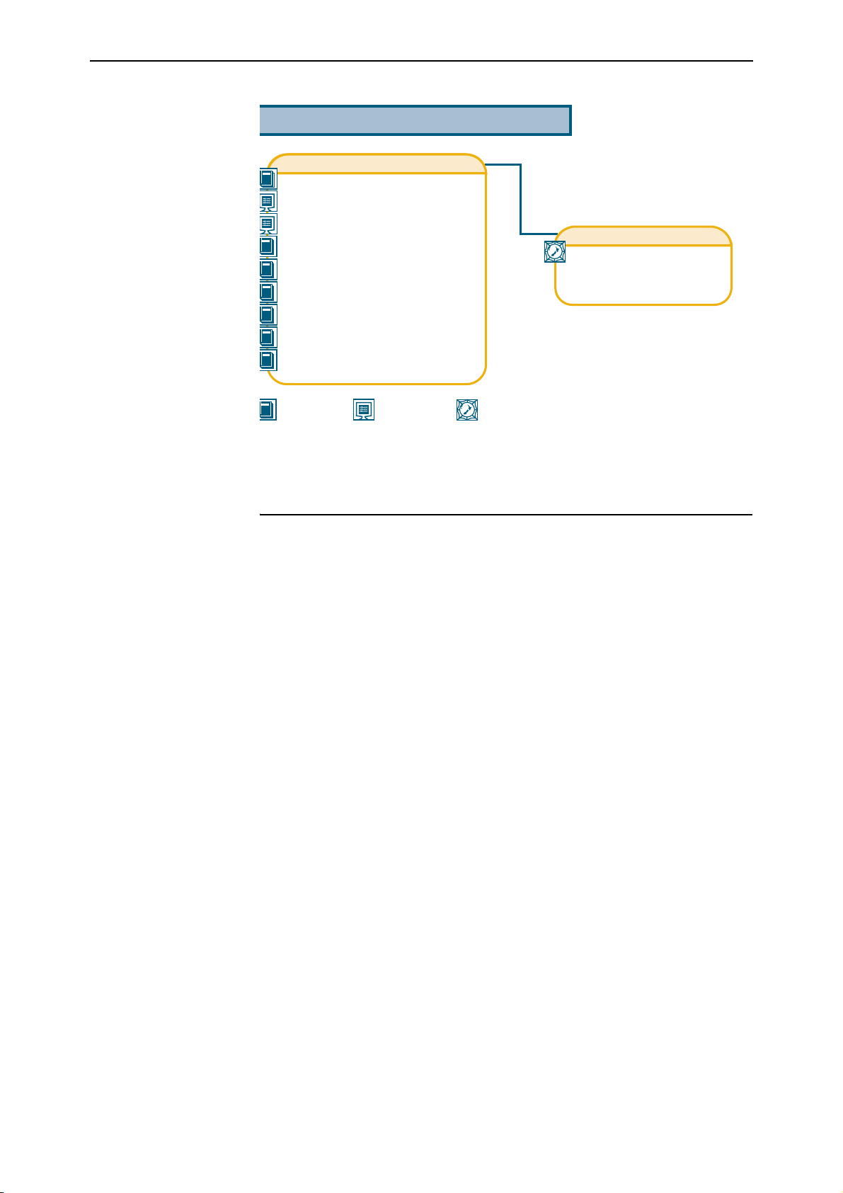
Documentation Roadmap
SwitchBlade
Safety and Statutory Information Booklet
Hardware Reference
Software Reference
Chassis & Fan Tray Quick Install Guide
Power Supply Unit Quick Install Guide
Switch Controller Quick Install Guide
Line Card Quick Install Guide
Bandwidth Expander Quick Install Guide
CAM Quick Install Guide
General Customer Support
Visit www.alliedtelesyn.co.nz for
the latest documentation, FAQs,
and support information.
Printed Acrobat PDF
Website
Models Covered by this Reference
This Hardware Reference includes information on the following SwitchBlade
components:
■ AT-SB4108-00 SwitchBlade 8 Triple AC Feed Chassis
■ AT-SB4108-60 SwitchBlade 8 Dual AC Feed Chassis
■ AT-SB4108-80 SwitchBlade 8 Dual DC Feed Chassis
■ AT-SB4104-00 SwitchBlade 4 AC Chassis
■ AT-SB4104-80 SwitchBlade 4 DC Chassis
■ AT-SB4161 SwitchBlade AC Power Supply Unit
■ AT-SB4161-80 SwitchBlade DC Power Supply Unit
■ AT-SB4162-V2 SwitchBlade AC Power Supply Unit
■ AT-SB4162-80 SwitchBlade DC Power Supply Unit
■ AT-SB4152 SwitchBlade 8 Fan Tray
C613-03060-00 REV H
■ AT-SB4151 SwitchBlade 4 Fan Tray
■ AT-SB4211 Switch Controller
■ AT-SB4215 Bandwidth Expander
■ AT-SB4311 48-port 10BASE-T/100BASE-TX (RJ-45) Line Card
■ AT-SB4352 32-port 100BASE-FX (MT-RJ) Line Card
■ AT-SB4412 24-port Gigabit (RJ-45) Line Card
■ AT-SB4442 24-port 1000Base-X (SFP) Line Card
■ AT-SB4441 8-port 1000BASE-X (GBIC) Line Card
■ AT-SB4541 1-port 10GBASE-LE (XFP) Line Card
6 SwitchBlade 4000 Series Switch
The latest SwitchBlade Hardware Reference can be found at
www.alliedtelesis.com/support/software.
Why You Should Read this Reference
This reference provides hardware related information for the SwitchBlade,
including information on the chassis, switch controllers, line cards, power
supplies, and fan tray.
The reference has two primary aims:
1. To familiarise you with the SwitchBlade’s hardware features.
2. To assist you with setting up and maintaining your SwitchBlade’s
hardware.
Step by step instructions for installing specific SwitchBlade components (such
as switch controllers and line cards) can be found in the Quick Install Guide for
each component.
Keep this reference (or its CD-ROM) in a safe place, you will need it if you purchase
switch expansion options, such as line cards, in the future.
This reference does not cover software configuration or software installation procedures.
For information on software, refer to the SwitchBlade Software Reference.
Where to Find More Information
The Documentation and Tools CD-ROM bundled with each switch controller
and chassis contains the complete document set for the switch and its
expansion options, as well as tools for managing the switch. This includes the
following:
■ SwitchBlade Safety Booklet - Provides safety and statutory information.
■ SwitchBlade Software Reference - Provides detailed information on
configuring the switch and its software.
■ SwitchBlade Chassis and Fan Tray Quick Install Guide - Outlines the procedure
for installing chassis and fan trays.
■ SwitchBlade Switch Controller Quick Install Guide - Outlines the procedure for
installing switch controllers.
■ SwitchBlade Line Card Quick Install Guide - Outlines the procedure for
installing line cards.
■ SwitchBlade Power Supply Unit Quick Install Guide - Outlines the procedure
for installing AC and DC PSUs.
■ SwitchBlade Bandwidth Expander Quick Install Guide - Outlines the procedure
for installing bandwidth expanders.
■ AT-TFTP Server for Windows - Provides a facility for downloading software
versions.
C613-03060-00 REV H

Hardware Reference 7
■ Adobe Acrobat Reader - Provides a facility for viewing online documentation
in PDF format.
The documents listed here can also be downloaded from the SwitchBlade
www.alliedtelesis.com/support/software.
SwitchBlade Overview
This section provides an introduction to the SwitchBlade’s hardware and
operational characteristics.
Key Hardware Components
SwitchBlade switches are based on a modular design. Several key components
(or modules) are required before the switch will function, these are listed
below:
• Chassis - Contains and interconnects switch components.
• Power Supply Units (PSU) - Provides a number of low voltage DC
supplies for the switches’ internal circuitry. Users may specify either
AC or DC power supplies. For some switch configurations two PSUs
may be necessary, plus an additional PSU where N+1 redundancy is
required.
• Fan tray - Provides cooling fans for the switch and line cards.
• Line cards - Provides layer 2/3 switching and the physical interfaces for
connecting the cables/fibre. Additional line cards may be added to
provide more ports and more port types than can be supplied by a
single card.
• Switch controller - Provides advanced switching operations and
configuration ports for the switch. An additional switch controller may
be added to increase speed and provide switch processing redundancy.
The SwitchBlade’s modular design delivers both reliability and scalability.
Dual switch controllers and multiple power supply units provide the
redundancy needed to ensure continuous network service. Line cards
incorporating Ethernet, fast Ethernet, and gigabit Ethernet (with both copper
and fibre interface options) are supported to meet the needs of rapidly
evolving networks.
Chassis Models
C613-03060-00 REV H
SwitchBlade chassis are available in two fundamental types: an eight slot
chassis (AT-SB4108), and a four slot chassis (AT-SB4104).
The eight slot chassis (AT-SB4108) provides space for the following units:
• two switch controller cards
• eight line cards
• three PSUs
• one AT-SB4151 fan tray
• one cable manager with four loops

8 SwitchBlade 4000 Series Switch
The four slot chassis (AT-SB4104) provides space for the following units:
• two switch controller cards (or one switch controller and one
bandwidth expander)
•four line cards
•two PSUs
• one AT-SB4151 fan tray
Both chassis types are available in either AC or DC power supply.
The eight slot AC chassis models can be supplied with either dual or triple
power feeds. These models are listed below:
• AT-SB108-00 triple AC feed
• AT-SB108-60 dual AC feed
All the four slot and DC chassis models are supplied with dual power feeds.
All SwitchBlade controller cards and line cards are compatible with both the
four and eight slot chassis types. For example, an AT-SB4211 switch controller
can be used in both the eight slot chassis and the four slot chassis.
Eight Slot Triple Feed
Models
Eight Slot Dual Feed
Models
The bandwidth expander (AT-SB4215) can be used only in switch controller
bay B of the four slot chassis.
Fan trays can be used only in their own particular chassis type. The AT-SB4151
fan tray can only be used in the four slot chassis, while the AT-SB4152 fan tray
can only be used in the eight slot chassis.
Power Feed Options
The eight slot AC chassis is available with either triple AC power feeds or dual
AC power feeds. The eight slot DC chassis is only available with dual DC
power feeds.
In these models each power feed connects only to its own associated power
supply. Therefore, if power to a particular feed is lost, then the PSU associated
with that feed will cease to operate. If the chassis contains three PSUs then
power will continue be drawn from the remaining two PSUs. However, with
only two PSUs installed, a disconnected power feed will result in power only
being supplied from the single remaining PSU, which, depending on
configuration, may - or may not - be sufficient to meet the chassis’ full power
requirements.
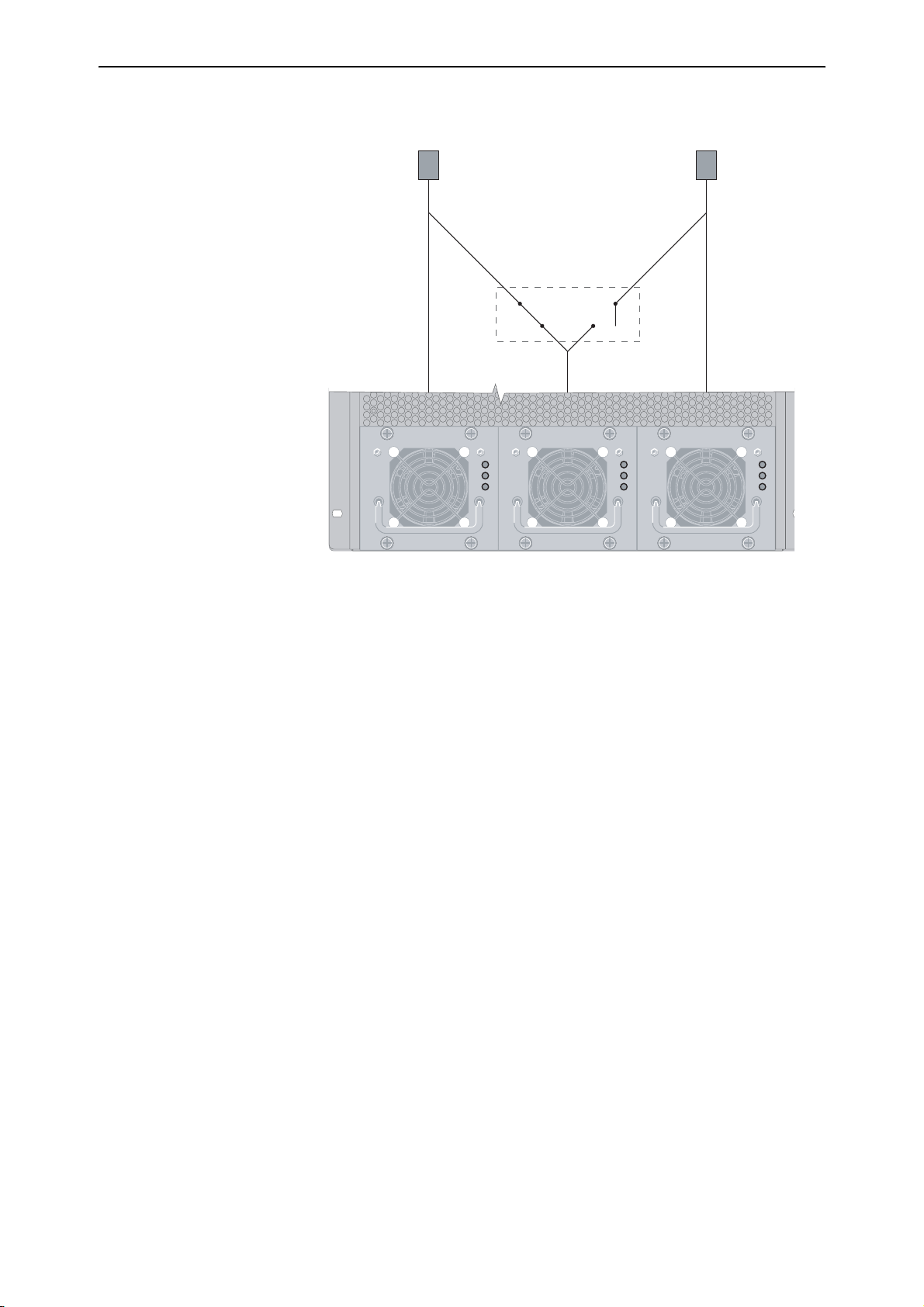
In these models, two feeds supply power to the chassis, which can contain up
to three PSUs. To provide power feed redundancy, a relay is used to enable
each of the two feeds to supply power to both its own PSU, plus the PSU
located in the centre bay, as shown.
C613-03060-00 REV H
Hardware Reference 9
Power Feed 1
Power Feed 2
Relay
AT-SB4162 AC POWER SUPPLY
AT-SB4162 AC POWER SUPPLY
DC
DC
GOOD
GOOD
FAN
FAN
GOOD
GOOD
POWER
POWER
PRESENT
PRESENT
AT-SB4162 AC POWER SUPPLY
AT-SB4162 AC POWER SUPPLY
DC
DC
GOOD
GOOD
FAN
FAN
GOOD
GOOD
POWER
POWER
PRESENT
PRESENT
PSU 1 PSU 2 PSU 3
AT-SB4162 AC POWER SUPPLY
DC
GOOD
FAN
GOOD
POWER
PRESENT
Dual Power Feed Connections
In the default mode, power feed1 supplies power to PSU 1 and PSU 2, and
power feed 2 supplies power only to PSU 3. Power feed redundancy is
provided as follows:
■ If power is disconnected from power feed 2, then PSU 1 and PSU 2 will
continue to supply power from power feed 1.
■ If power is disconnected from feed 1, then the relay will switch to
disconnect PSU 2 from power feed 1 and reconnect it to power feed 2. DC
power will then be provided via PSU 2 and PSU 3.
Power Supplies
The SwitchBlade chassis and power supplies offer a number of options such as
hot swapping that provide varying degrees of resiliency and recovery.
See “Power Feed Options” on page 8, “AT-SB4161 & 2 SwitchBlade Power
Supply Units” on page 19, and “How Many PSUs do You Need?” on page 33.
C613-03060-00 REV H

10 SwitchBlade 4000 Series Switch
Switching Performance and Characteristics
The SwitchBlade architecture is based on a non-blocking wire-speed Layer 2
and 3 switching fabric. Layer 3 switching is performed by line cards as well as
switch controllers. As with other Allied Telesis Layer 3 switches, the
SwitchBlade includes full multiprotocol routing capabilities.
Layer 3 switching performance is determined by the number of switch
controllers and line cards that are installed. If two switch controllers are
installed, each line card operates at maximum bandwidth. This provides
switching capacity of 192 Gbps for the 4 slot chassis, and 384 Gbps for the 8 slot
chassis. The 4 slot chassis can also achieve maximum bandwidth when one
switch controller and a bandwidth expander (AT-SB4215) are installed.
Master Switch Controller and Slave Switch Controller Interactions
The first switch controller to be installed in a chassis should be located in
switch controller bay A. This controller acts as the master switch controller,
performing all table updates and packet exception processing. Its “Master”
LED lights to confirm that it is the master switch controller.
When a second switch controller is installed, it is automatically designated
slave status. In this case the master still performs all table updates and packet
exception processing, but the switching load is shared between the two
controllers, while the slave maintains copies of the master’s routing tables.
Installing two switch controllers enables processing redundancy. If a switch
controller fails, or is removed, then the other controller assumes master status
and continues all processing operations. If the only operational controller is in
Bay B, then this will retain master status until an operational controller is
inserted in Bay A and a system reset or restart occurs.
Hot Swapping
Hot swapping is the replacement of a component (such as a line card) while the
switch is powered up. The following SwitchBlade components can be hot
swapped:
• Power supply units (PSUs). The switch will continue to operate as long
as sufficient functional PSUs remain in place to meet the switch’s power
demand. “How Many PSUs do You Need?” on page 33 provides more
information on switch configurations and their power demands.
Note that only certain power supplies are fully hot swapable and that
this ability relates to the PSU being inserted, not the one being removed.
The following PSUs are fully hot swapable: AT-SB4162-V2 AC PSU, and
AT-SB4162-80 DC PSU.
• Fan trays. Although the switch can operate for short periods without a
fan tray, such as while exchanging fan trays, it should not left running
for longer periods without a fan tray operating.
• Switch controllers. The switch will continue to operate as long as at least
one functional switch controller (master or slave) remains in place,
although a brief pause in switching and routing may occur. Packets
passing through the switch during a switch-controller hot swap will be
lost.
C613-03060-00 REV H

Hardware Reference 11
• Line cards. Equivalent cards can be exchanged without having to
reconfigure the switch. For example, if an AT-SB-4311 line card is
removed and replaced with a new AT-SB-4311 (in the same bay), the
new card will use the original card’s configuration (as long as the switch
is not restarted before the new card is installed).
The next section describes the configuration effects of hot-swapping a
line card.
Hot-swapping a Line Card
Line cards can be hot swapped without requiring without requiring any
notification to the switch. The SwitchBlade detects that a card is being removed
and sets itself to a safe state. Insertion of any card into the SwitchBlade is
detected and initialised automatically.
Hot-swapping line cards has the following scenarios:
■ A bay was previously empty and a card is being hot swapped in.
The line card powers up with no configuration, adding all of its ports to the
default VLAN.
■ A bay was previously occupied and a different card type is being hot
swapped in.
The line card powers up and is configured exactly as if the bay were
previously empty. Previous interfaces marked as swapped out for this bay
are replaced with new card interfaces.
■ A bay was previously occupied and the same card type is being hot
swapped in.
The previous VLAN configuration for the card is restored to its previous
condition and previous trunking settings are restored. Interfaces registered
against this card are marked up or down as appropriate. Switch table
entries are restored except for entries that are timed to allow natural expiry
(for example, MAC and IP multicast).
■ A line card is being removed from a bay.
Interfaces registered against this card are marked as swapped out. All
other modules treat these interfaces as being present but no longer active.
Before hot-swapping a line card out of the switch, we recommend that you
save the current configuration by using the command:
create config
Reconfiguring During Hot swap
After a line card has been hot swapped out, the switch can be reconfigured
before the removed line card is returned. The new configuration can be saved
by using the command:
C613-03060-00 REV H
create config
References to the missing ports are retained in the switch’s memory. The
configuration appears the same as if the line card had not been removed. To
display it, use the command:
show config dynamic
When the line card is hot swapped in again, whether its original configuration
is restored depends on the following factors:
12 SwitchBlade 4000 Series Switch
■ Whether a power cycle occurred between the create config command and
the line card being replaced, and
■ If a power cycle did occur, whether another create config command has
been entered.
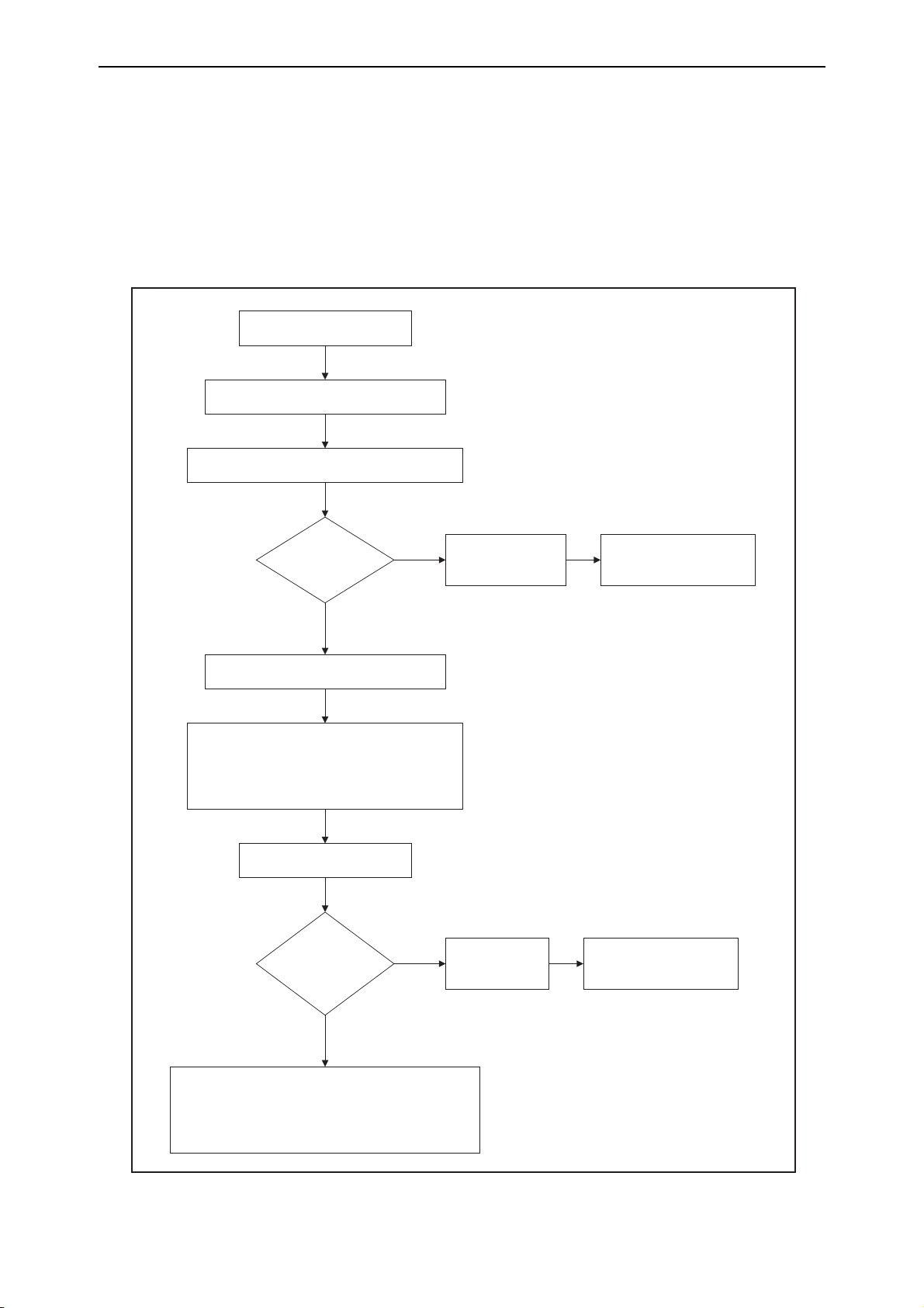
The process flow is shown in Figure 1-1 on page 12.
Figure 1-1: The process flow involved in hot swapping a line card out, changing the switch’s configuration, and then hot
swapping the line card back in
Line card is hotswapped out
The switch is reconfigured.
CREATE CONFIG command is execut ed.
Configuration of swapped-out card is retained,
including references t o miss ing ports .
Power cycle
occ urs?
Yes
Commands referring to missi ng port s fail on
start-up
Switch "remembers" commands with failed ports.
When the dynamic configuration is dis played with
SHOW CONFIG DYNA MIC, missing c ommands
show under "Swapped out" headings.
Card is hotswapped back in.
CREATE CONFIG
exec uted?
No
No
Card is hotswapped
back in.
Switch restarted.
Card's configuration is
restored to what it was
before it was removed.
Card's configuration is
restored to what it was
before it was removed.
Yes
Card's original configuration is lost.
Warning: under these c ircumstances, do not enter
CREATE CONFIG without first res tarting the swi tch,
unless you want t o delete t he original c onfiguration of the
previously-hotswapped card.
C613-03060-00 REV H
Hardware Reference 13
The most desirable situation is to avoid a power cycle before replacing the line
card. However, if a power cycle does occur, the line card’s original
configuration is saved by the switch and can be displayed by using the
command:
show config dynamic
Look for “Swapped out” headings in the Switch (post-VLAN and pre-VLAN),
STP, VLAN, QOS, and GARP sections. To restore the line card’s original
configuration, hot swap the line card back in and restart the switch by using
one of the commands:
restart switch
restart reboot
Do not enter the create config command before performing this restart unless
you want to delete the original configuration of the line card that you hot
swapped back in.
When a configuration file is manually edited, port ranges can only be entered
as a single term when the range does not span across line cards. For example, a
correct entry in a configuration file is:
add vlan=2 port=1.1-1.8,5.1-5.7
An incorrect entry is:
add vlan=2 port=1.1-5.7
If a range that spans several line cards is specified as a single term, the switch is
unable to determine at start-up whether any line cards within the range have
been removed.
This limitation does not apply when a range of ports is entered into a
command on the command line interface because the switch correctly splits the
range when performing a create config command.
Examples
The following examples describe possible scenarios where slots 1 and 2 are
occupied by 8-port line cards and Line Card 1 is hot swapped out.
1. Line Card 1 is removed after being configured via a boot configuration. A
line card of the same type is replaced in the slot.
The second line card is reconfigured to behave exactly as the original line
card. All switch table entries are restored except for entries timed to allow
natural expiry (for example, MAC and IP multicast). Changes to hardware
such as RDRAM or silicon version are used to the greatest extent possible
(for example, performance may change but functionality remains the same).
C613-03060-00 REV H
2. Line Card 1 is removed after being configured via a boot configuration. A
line card of a different type is replaced in the slot.
This situation is the same as if a line card were inserted into a system that
was previously unoccupied. The line card is initialised without
configuration. No configuration from the current configuration file is
applied.
3. Line Card 1 is removed after being configured via a boot configuration and
the slot is left empty.

14 SwitchBlade 4000 Series Switch
The switch’s configuration maintains the swapped-out settings. These
result in error messages on start-up, but do not affect the functioning of the
switch. The configuration can be manually edited to remove the swapped
sections that no longer apply.
4. Line Card 1 has been configured and then removed before the configuration
was saved using the create config command. The user then wishes to enter
this command, while keeping the previous configuration of the line card
that has been hot swapped out.
When the create config command is entered, the switch retains the
configuration of the line card that has been hot swapped out. For example,
if the original configuration included the command add vlan=”V2”
port=1.1-2.4, the show config dynamic command would display the
following configuration even though ports 1.1-1.8 no longer exist:
#
# vlan configuration
#
add vlan="v2" port=1.1-1.8
add vlan="v2" port=2.1-2.4
If the switch is then restarted, some of the commands fail and the resulting
dynamic configuration is:
#
# vlan configuration
#
add vlan="v2" port=2.1-2.4
#
# vlan swapped out port configuration
add vlan="v2" port=1.1-1.8
This situation is potentially problematic because the switch has been
restarted before the line card was hot swapped back in. The remaining
examples describe possible ramifications.
5. (continuing from the end of Example 4) The switch is powered down and a
different type of line card (for example, a 48-port line card) is inserted into
slot 1. The switch is then powered up.
Ports 1.1-1.8 are configured as they were for the original 8-port line card.
The remaining ports are added to the default VLAN.
Ultimately the line card is initialised to match as many of the commands
that were previously configured as possible (some settings such as port
speed are not possible).
6. (continuing from the end of Example 4) A line card is inserted into slot 1,
and the configuration saved by using the command:
create config
The line card is initialised without configuration because the commands
stored in the swapped out configuration that refer to this slot are all
removed when the user creates a configuration.
Before the new line card was inserted, the configuration displayed by the
show config dynamic command would have been:
#
# vlan configuration
C613-03060-00 REV H

Hardware Reference 15
#
add vlan="v2" port=2.1-2.4
#
# vlan swapped out configuration
add vlan="v2" port=1.1-1.8
After the new line card is inserted and the create config command is
entered, the show config dynamic command displays the following
configuration:
#
# vlan configuration
#
add vlan="v2" port=2.1-2.4
7. (continuing from the end of Example 4) The wrong line card is accidentally
inserted into slot 1. The user realises the mistake and removes the line card.
The user has also already made further configuration changes, and saves
the configuration by using the command:
create config
Because the line card that was inserted by accident has been hot swapped,
creating a configuration removes the commands stored in the swapped-out
configuration. When the correct line card is inserted, it is initialised without
configuration.
To avoid loss of the swapped-out configuration in this situation, insert the
correct line card, and restart the SwitchBlade. Then make the other
configuration changes and create the configuration.
Physical and Operating Specifications
This section provides an overview of the SwitchBlade’s physical and operating
specifications.
AT-SB4108 SwitchBlade 8 Card Chassis
Dimensions
• Height: 666 mm (15U rack occupancy)
• Width: 440 mm (excluding rack-mounting brackets). Suitable for 19
inch racks
• Depth: 392.5 mm (539 mm if a cable manager is attached)
• Chassis 8 weight: 19 kg (empty chassis)
C613-03060-00 REV H
• Chassis 8 loaded Weight: 34 to 63.5 kg (depending on the configuration)
Environmental Conditions
• Operating temperature range: 0 to 40º C (32 to 104º F)
• Storage temperature range: -25 to 70º C (-13 to 158º F)
• Relative humidity range: 5 to 95% non-condensing

16 SwitchBlade 4000 Series Switch
Regulatory Standards
• EMC: EN55022 class A, FCC class A, and VCCI class I
• Immunity testing to EN55024: EN61000-4 levels 2 (ESD), 3
(susceptibility), 4 (fast transients), 5 (power surge), 6 (RF immunity),
and 11 (Voltage dips and sags; EN61000-3 levels 2 (Harmonics), and 3
(Flicker)
• Safety: UL60950, CAN/CSA-C22.2 No. 60950-00, EN60950, ACA TS001
Power Supply Options
For PSU specifications and maximum current loads, see “AT-SB4161 & 2
SwitchBlade Power Supply Units” on page 19. The number of PSUs
required depends on the particular configuration selected.
Note: Because certain chassis models contain additional circuitry to control power
supply switching, the voltage ranges specified for the chassis can differ from those
separately specified for the power supply.
AC models
• AT-SB4108-00 Triple AC Feed (100 to 240) V AC, (50 to 60) Hz
input
• AT-SB4108-60 Dual AC Feed (200 to 240) V AC, (50 to 60) Hz
input
DC models
• 48 V DC. Operating voltage range (40 to 60) V DC
• Accepts positive or negative earthing (grounding)
LEDs
• System status LEDs on each switch controller
• Port LEDs on each line card
• Power supply status LEDs on each PSU and switch controller
• For a complete list of LEDs and their functions, see “LEDs and What
They Mean” on page 47
Configuration and Management Ports (AT-SB4211 switch controller)
• Standard DB9 female RS-232 connector for configuration and low-level
management (on switch controller)
• 10/100 TX RJ-45 port for switch management (on switch controller)
See “AT-SB4211 and AT-SB4211 V2, Switch Controller” on page 22 for more
information on management ports
Mounting System
• 19 inch rack mounting
• Front rack-mounting brackets incorporated in chassis. Mid or rear
mounting brackets optional
C613-03060-00 REV H

Hardware Reference 17
Expansion Bays
• Two switch controller bays
• Eight line card bays
• Three power supply bays
• One fan tray bay (compatible with the AT-SB4152 fan tray)
Alarm Relays
• Two relays (Major and Minor) each located on the rear panel
• Normally open and normally closed contacts
• Software configurable for a range of environmental and operational
events
• Suitable for use with DC alarm circuits (12 V DC 1.0 A or 48 V DC 0.5 A)
• See “Alarm Relays and Monitoring” on page 32 for more information
Backplane Links and Bus Connections
• A SwitchBlade chassis contains two controller bays each capable of
housing a switch controller card. See “Switching Performance and
Characteristics” on page 10 for more information.
• 33MHz 64 bit PCI routing and control bus links are present on all switch
controller and line card bays. This bus provides a high performance
communication channel between switch controller CPUs, and also
allows high speed routing between line cards that have WAN interfaces
Cable Management System
• Optional manager can be fitted to the fan tray front panel
• Cable manager supports up to four cable-management loops
Earth/Ground Point
• An earth/ground point is provided on the chassis’s rear panel. This
point can be used to bond the cha ssis to earth/ground. Even if this point
is used, earth/ground leads of AC and DC power supplies must still be
connected
AT-SB4104 SwitchBlade 4 Slot Chassis
Dimensions
• Height: 400 mm 9U rack occupancy
• Width: 440 mm (excluding rack-mounting brackets). Suitable for 19
inch rack
C613-03060-00 REV H
• Depth: 345 mm
• Chassis 4 (AC) weight: 13 kg (empty chassis)
• Chassis 4 (DC) weight: 13 kg (empty chassis)
• Chassis 4 loaded weight: 23 kg to 45 kg (depending on the
configuration)

18 SwitchBlade 4000 Series Switch
Environmental Conditions
• Operating temperature range: (0 to 40) ºC, (32 to 104) ºF
• Storage temperature range: (-25 to +70) ºC, (-13 to +158) ºF
• Relative humidity range: 5 to 95% non-condensing
Regulatory Standards
• EMC: EN55022 class A, FCC class A, and VCCI class I
• Immunity testing to EN55024: EN61000-4 levels 2 (ESD), 3
(susceptibility), 4 (fast transients), 5 (power surge), 6 (RF immunity),
and 11 (Voltage dips and sags; EN61000-3 levels 2 (Harmonics), and 3
(Flicker)
• Safety: UL60950, CAN/CSA-C22.2 No. 60950-00, EN60950, ACA TS001
Power Supply Options
For PSU specifications and maximum current loads, see “AT-SB4161 & 2
SwitchBlade Power Supply Units” on page 19. The number of PSUs
required depends on the particular configuration selected, i.e. the number
of line cards, controller cards installed. Consult your authorised Allied
Telesis distributor or reseller for more information.
Note: Because certain chassis models contain additional circuitry to control power
supply switching, the voltage ranges specified for the chassis can differ from those
separately specified for the power supply.
AC models
• Universal (110 to 240) V AC, (50 to 60) Hz input
DC models
• 48 V DC, (40 to 60) V DC operating range
• Accepts positive or negative earthing (grounding)
LEDs
• System status LEDs on each switch controller
• Port LEDs on each line card
• Power supply status LEDs on each PSU and switch controller
• For a complete list of LEDs and their functions, see “LEDs and What
They Mean” on page 47
Configuration and Management Ports (AT-SB4211 switch controller)
• Standard DB9 female RS-232 connector for configuration and low-level
management (on switch controller)
• 10/100TX RJ-45 port for switch management (on switch controller)
See “AT-SB4211 and AT-SB4211 V2, Switch Controller” on page 22 for more
information on management ports
C613-03060-00 REV H

Hardware Reference 19
Mounting System
• 19 inch rack mounting
• Front rack-mounting brackets incorporated in chassis. Mid or rear
mounting brackets optional
Expansion Bays
• Two switch controller bays
•Four line card bays
• Two power supply bays
• One fan tray bay (compatible with the AT-SB4151 fan tray)
Alarm Relays
• Two relays on rear panel
• Normally open and normally closed contacts
• Software configurable for a range of conditions
• See “Alarm Relays and Monitoring” on page 32 for more information
Backplane Links and Bus Connections
• A SwitchBlade chassis contains two controller bays each capable of
housing a switch controller card. See “Switching Performance and
Characteristics” on page 10 for more information.
• 33 MHz 64 bit PCI routing and control bus links all switch controller
and line card bays. This bus provides a high performance
communication channel between switch controller CPUs, and also
allows high speed routing between line cards that have WAN
interfaces.
Earth/Ground Point
• An earth/ground point is provided on the chassis’s rear panel. This
point can be used to bond the cha ssis to earth/ground. Even if this point
is used, earth/ground leads of AC and DC power supplies must still be
connected.
AT-SB4161 & 2 SwitchBlade Power Supply Units
For guidelines on how many PSUs are required for a particular configuration,
see “How Many PSUs do You Need?” on page 33.
LEDs
C613-03060-00 REV H
• Three LEDs indicate power supply status (input, output, and fan status)
• For a complete list of LEDs and their functions, see “LEDs and What
They Mean” on page 47
Power Supply Specifications
Weight
• 3.6 kg

20 SwitchBlade 4000 Series Switch
Cooling
•Built-in fan
• Monitoring of PSU fans for stalled or slow speed
LEDs
• Three LEDs indicate power supply status (input, output, and fan status)
• For a complete list of LEDs and their functions, see “LEDs and What
They Mean” on page 47
Electrical Specifications Per Chassis Type
Eight Slot Triple Feed AC Chassis (SB4108-00)
• (100 to 240) V AC (50 to 60) Hz input
For a fully loaded chassis with eight line cards and a fan tray installed
• Maximum continuous current draw for each active PSU, 4 A at 240 V,
8 A at 120 V (due to load sharing, redundant PSUs do not add to the
total continuous current drawn).
• Maximum inrush current for each PSU (cold start), 75 A at 240 V, 37 A
at 120 V.
Eight Slot Dual Feed AC Chassis (SB4108-60)
• 200 V to 240 V AC (50 to 60) Hz input
For a fully loaded chassis with eight line cards and a fan tray installed
• Maximum continuous current draw for each active power feed, 8Aat
240 V, 16 A at 120 V.
• Maximum inrush current for each power feed (cold start), 150 A at
240 V, 75 A at 120 V.
Four Slot Dual Feed AC Chassis (SB4104-00)
• 100 V to 240 V AC (50 to 60) Hz input
For a fully loaded chassis with eight line cards and a fan tray installed
• Maximum continuous current draw for each active power feed, 8A at
240 V, 16 A at 120 V.
• Maximum inrush current for each PSU (cold start), 75 A at 240V, 37 A at
120V.
Eight Slot Dual Feed DC Chassis (SB4108-80)
Fully loaded chassis with four line cards and a fan tray installed
• Maximum continuous current draw for each active power feed, 30A
within the rated input voltage range.
• Maximum inrush current for each PSU (cold start), A within the rated
input voltage range.
• Accepts positive or negative earthing (grounding)
C613-03060-00 REV H
Loading...