

Page 1
FACTORY PRESET
DOCUMENTATION
Page 2
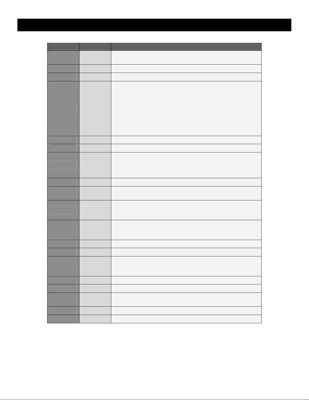
MPD32 FACTORY PRESET LISTINGS
PRESET # PROGRAM DESCRIPTION
1 LiveLite
2 FxPanBFD
3 MPC Pads
4 Reason
5 Cubase
6 ApplidAc
7 Arturia
8 FLStudio
9 FxPanGUR
10 GMedia
11 RobPapen
12 Sonar
13 SpectATM
14 SpectRMX
15 SpectTRL
16 Virsyn
17 GMDrums
18 ArkaosVJ
19-30 Generic
The presets included are only intended to be a starting point for your use. All of these software programs allow incredible
amounts of control and by using multiple MIDI channels, controllers, pad modes and program changes, you can easily
create some incredible music.
Enjoy.
This preset is designed to be used with the Ableton Live Lite
software DAW, included with the MPD32.
For use with Fxpansion’s BFD.
For use with the Akai MPC series.
This preset supports the Reason Remote protocol with supplied
codec files. To use Reason with the Remote protocol, you will
need to install the supplied Reason codec files. Each module in
Reason will automatically map itself to the MPD32’s controllers.
This is extremely powerful as it allows you to use a single
MPD32 preset to control all of the modules in Reason. See
“Using the MPD32 with Propellerheads Reason” section for
information on installing the Reason Remote codecs and
mappings
For use with Steinberg’s Cubase DAW.
For use with Appliead Acoustics’ String Studio and Ultra Analog.
For use with Arturia software synth modules, such as Arp2600V,
CS80V, Moog Modular V, Minimoog V, Prophet V, Jupiter 8V.
See “Using the MPD32 with Arturia Synths” for information on
preset mappings.
For use with Image Line’s FL Studio 7.
For use with Fxpansion’s Guru. See “Using the MPD32 with
Fxpansion’s Guru” for mapping information and use.
For use with Gmedia synths, such as Minimonsta, ImpOSCar,
and Oddity. See “Using the MPD32 with Gmedia Synths” for
mapping information and use.
For use with Rob Papen synths, such as LinPlug's Albino 3, and
ConcreteFX's Blue and Predator,. See “Using the MPD32 with
Rob Papen Synths” for mapping information and use.
For use with Cakewalk Sonar DAW.
For use with Spectrasonics’ Atmosphere.
For use with Spectrasonics’ Stylus RMX. See “Using the
MPD32 with Spectrasonics’ Stylus RMX” for mapping
information and use.
For use with Spectrasonics’ Trilogy.
For use with Virsyn synths, such as Poseidon and Tera 3.
Standard General MIDI drum and controller mapping. Good for
general drum use.
For use with Arkaos VJ.
Page 3

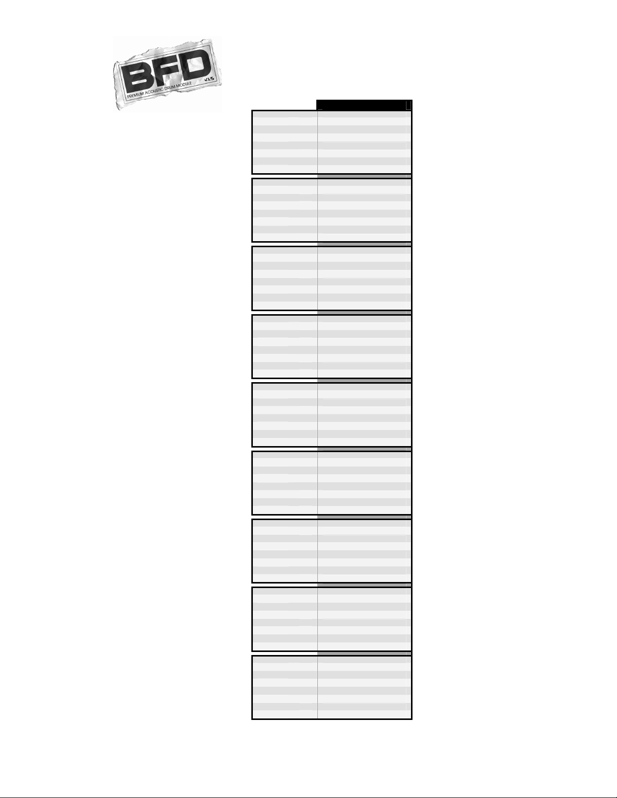
USING THE MPD32 WITH BFD
BFD is the premiere software drum module, featuring high-quality drum samples for realistic
drum performance. BFD can be used as a standalone computer application, or as a VST
instrument which can be dropped into your favorite host environment.
We have included a default MIDI map for BFD which gives you access to all the major features
of the software.
The MPD32 comes with a preset which is already set up to work with BFD.
1. To use the FxpanBFD preset you will need to copy the Akai_MPD32_BFD.bfc file from the CD to your BFD
folder on your hard drive. This BFD folder has all of your FILLS, GROOVES, KEYMAPS, KITS etc. You will find
a file labeled default.bfc – place the Akai_MPD32_BFD.bfc file at this same directory level.
2. To load this MIDI CC map file, start BFD and click on the HIT OPTIONS icon on the middle right of the BFD
screen.
a. This will open a dialog box that has PAGE1, PAGE2, ADVANCED and MIDI CC's options.
b. Click on the MIDI CC's tab.
c. Now to the left of the PAGE 1 option, click on the LOAD MIDI CC ASSIGNMENTS icon.
d. Choose the Akai_MPD32_BFD.bfc file and BFD will now be mapped to correspond to the FxPanBFD
preset on the MPD32.
3. To load the preset in the MPD32, press the [PRESET] button and use the [VALUE] dial to select preset number 7
– “FxPanBFD”. Press the [VALUE] dial to load the preset.
NOTE: If you want this MIDI CC file to be the default MIDI CC map on BFD, rename the file default.bfc and it will
automatically load every time.
If you have edited MPD32’s presets and are unable to load BFD, use the
supplied Vyzex Editor to load the Factory Preset Bank and “PUT” or download
!
the factory preset bank into the MPD32.
Page 4
AKAI MPD32 PRESET MAPPINGS
Fader 1
Fader 2 A
Fader 3 A
Fader 4 A
Fader 5 A
Fader 6 A
Fader 7 A
Fader 8 A
Knob 1
Knob 2 A
Knob 3 A
Knob 4 A
Knob 5 A
Knob 6 A
Knob 7 A
Knob 8 A
Switch 1
Switch 2 A
Switch 3 A
Switch 4 A
Switch 5 A
Switch 6 A
Switch 7 A
Switch 8 A
Fader 9
Fader 10 B
Fader 11 B
Fader 12 B
Fader 13 B
Fader 14 B
Fader 15 B
Fader 16 B
Knob 9
Knob 10 B
Knob 11 B
Knob 12 B
Knob 13 B
Knob 14 B
Knob 15 B
Knob 16 B
Switch 9
Switch 10 B
Switch 11 B
Switch 12 B
Switch 13 B
Switch 14 B
Switch 15 B
Switch 16 B
Fader 17
Fader 18 C
Fader 19 C
Fader 20 C
Fader 21 C
Fader 22 C
Fader 23 C
Fader 24 C
Knob 17
Knob 18 C
Knob 19 C
Knob 20 C
Knob 21 C
Knob 22 C
Knob 23 C
Knob 24 C
Switch 17
Switch 18 C
Switch 19 C
Switch 20 C
Switch 21 C
Switch 22 C
Switch 23 C
Switch 24 C
BANK
BFD LITE
A DIRECT MASTER
OVERHEAD
ROOM
PZM
MASTER
Master Dynamics
Kick Mic In/Out
Snare Mic Top/Bottom
A OVERHEAD DISTANCE
OVERHEAD WIDTH
ROOM DISTANCE
ROOM WIDTH
PZM DISTANCE
PZM WIDTH
A DIRECT MASTER MUTE
OVERHEAD MUTE
ROOM MUTE
PZM MUTE
DIRECT MASTER SOLO
OVERHEAD SOLO
ROOM SOLO KICK SOLO
PZM SOLO
B KICK 1 Direct TRIM
SNARE 1 Direct TRIM
HIHAT Direct TRIM
TOM F Direct TRIM
TOM M Direct TRIM
TOM H Direct TRIM
CYM 1 Direct TRIM
CYM 2 Direct TRIM
B KICK 1 Direct PAN
SNARE 1 Direct PAN
HIHAT Direct PAN
TOM F Direct PAN
TOM M Direct PAN
TOM H Direct PAN
CYM 1 Direct PAN
CYM 2 Direct PAN
B KICK MUTE
SNARE MUTE
HIHAT MUTE
TOM F MUTE
TOM M MUTE
TOM H MUTE
CYM 1 MUTE
CYM 2 MUTE
C KICK TRIM
SNARE TRIM
HIHAT TRIM
TOM F TRIM
TOM M TRIM
TOM H TRIM
CYM 1 TRIM
CYM 2 TRIM
C KICK TUNE
SNARE TUNE
HIHAT TUNE
TOM F TUNE
TOM M TUNE
TOM H TUNE
CYM 1 TUNE
CYM 2 TUNE
C KICK SOLO
SNARE SOLO
HIHAT SOLO
TOM F SOLO
TOM M SOLO
TOM H SOLO
CYM 1 SOLO
CYM 2 SOLO
Page 5
USING THE MPD32 WITH REASON
Reason is a software program that allows for vast control of its parameters. The
problem with having a lot of controllable items is the limit of physical space and the
cost of building hardware controllers that can accommodate hundreds or thousands
of controllers. The people at Propellerheads have developed a way to remap a single
control surface to each of the modules in Reason. This protocol is called Reason
Remote.
We have included all the files necessary to enable Reason to find the MPD32 and map its controls to whatever module
you have selected in the sequencer.
To begin using the MPD32 with Reason, you will need to make sure that you have version 3.0.5 or greater for the Mac or
version 3.0.4 or later for the PC. Please note that the MPD32 is also compatible with Reason 4.
1. To install the Reason Remote codecs and remote maps, run the Reason Remote installer for your particular
computer and it will auto-install the folders into the right locations.
2. After you have installed the Reason Remote codecs, select Preset number 2 – “Reason” – on your MPD32.
Press the [VALUE] dial to load the preset.
If you have edited MPD32’s presets and are unable to load the Reason preset, use the supplied Vyzex
!
Editor to load the Factory Preset Bank and “PUT” or download the factory preset bank into the MPD32.
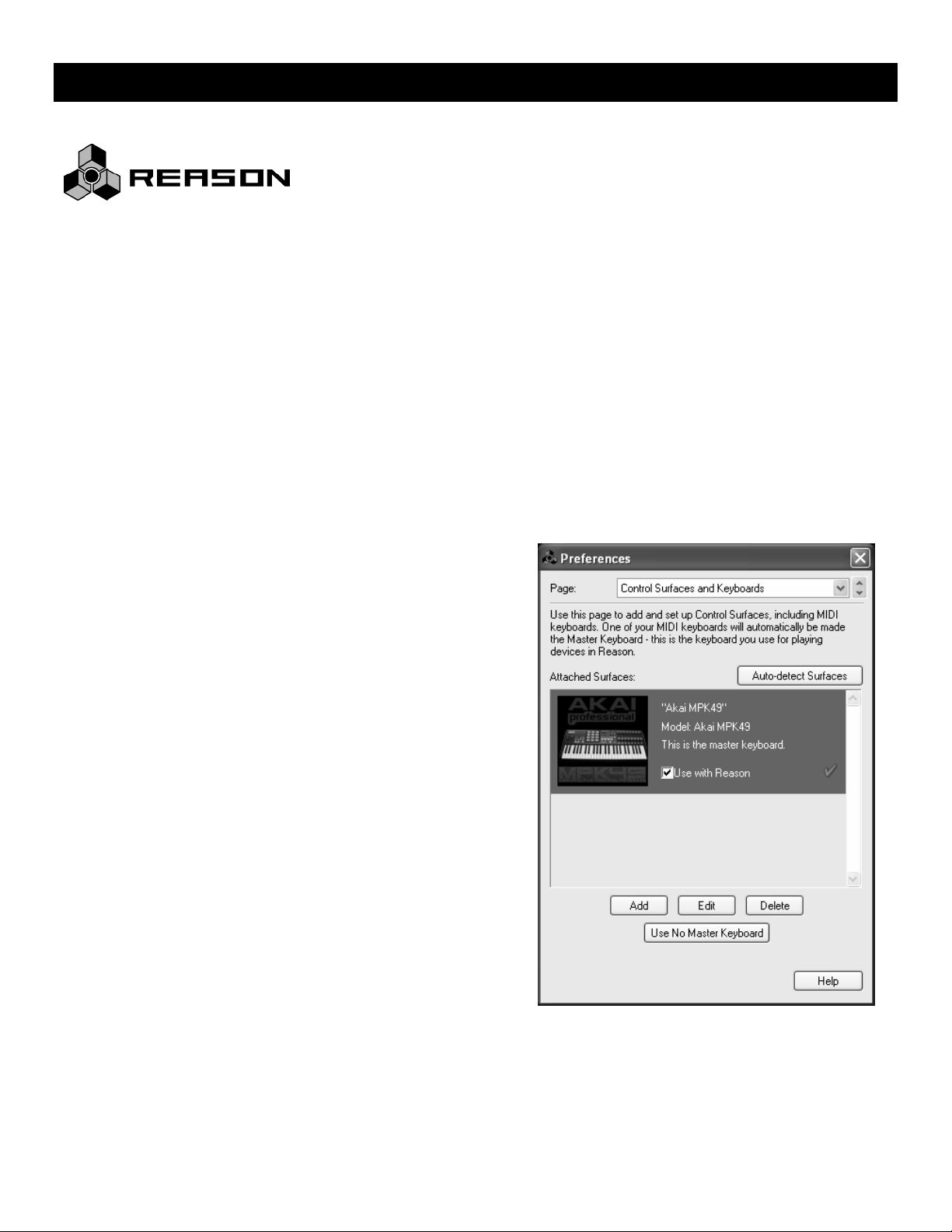
3. Start up Reason and the software will automatically find the
MPD32 controller. Within Reason, click on [Preferences]
and look under [Control Surfaces and Keyboards]. You
should see the Akai MPD32 icon with a green check mark.
If it is not checked, click the “Use with Reason” button.
Page 6
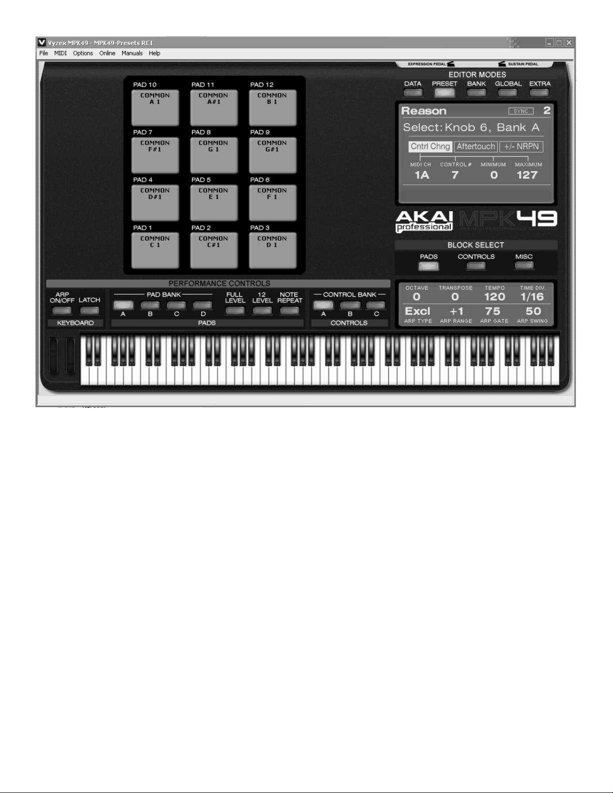
The Vyzex Editor included on the CD is a great way to customize or restore presets to their factory condition!
The MPD32 preset for Reason makes use of pad banks A, B and C for playing notes. With these three pad banks you get
a 3-octave range of pitch control.
Pad bank D is configured to be used as a control bank. This pad bank allows you to use the pads as switches for certain
features.
The mapped parameters are shown in the graphic above.
EXAMPLE:
When you are controlling Redrum or Matrix, pads D1-D4 correspond to the Bank A, B, C, D buttons in the pattern
section. Pads D9-12 will allow you to select between patterns 1-4 and pads D5-8 allow you to select between
patterns 5-8.
In modules that allow you to select the “Previous” or “Next” preset, you can use switch S15 for “Previous Preset”
and switch S14 for “Next Preset”.
Switches S7 and S8 are always assigned to target the next or previous sequence track. This allows you to
remotely select which module you are controlling.
The next few pages feature a full table of the mapping functions. Please refer to this table for information on how the
MPD32 controls map to each individual module in Reason. You can always change how controllers are mapped by
modifying the “MPD32.remotemap” file. This will allow you to customize how Reason and your MPD32 work.
Page 7
AKAI MPD32 PRESET MAPPINGS
::: GLOBAL CONTROLLERS :::
MPD32 CONTROL REASON FUNCTION MPD32 CONTROL REASON FUNCTION
Record Record Mod Wheel Mod Wheel
Rewind
Fast Forward
Switch 7
Switch 8 Target Next Track
Switch 15
Switch 16
Switch 23
Switch 24
RV 7000
REVERB
BANK
Decay Damage Control Low Shelf Gain Low Width Input Gain Input Gain Algorithm
Fader 1
Fader 2 A
Fader 3 A
Fader 4 A
Fader 5 A
Fader 6 A
Fader 7 A
Fader 8 A
Knob 1
Knob 2 A
Knob 3 A
Knob 4 A
Knob 5 A
Knob 6 A
Knob 7 A
Knob 8 A
Switch 1
Switch 2 A
Switch 3 A
Switch 4 A
Switch 5 A
Switch 6 A
Switch 7 A
Switch 8 A
A
HF Damp Damage Type Parametric 1 Gain X-Over Frequency Threshold Attack Speed Size
Hi EQ Parameter 1 Parametric 2 Gain High Width Ratio Release Speed Decay
Dry/Wet Parameter 2 Hi Shelf Gain Solo Mode Attack Output Gain Damping
Cut Lo Low Shelf Q Release Soft Clip Amount Dry/Wet
Cut Mid Parametric 1 Q Output Gain
Cut Hi Parametric 2 Q
Soft Knob 1 Body Resonance Low Shelf Frequency
A
Soft Knob 2 Body Scale Parametric 1 Frequency
Soft Knob 3 Body Auto Parametric 2 Frequency
Soft Knob 4 Body Type Hi Shelf Frequency
Soft Knob 5
Soft Knob 6
Soft Knob 7
Soft Knob 8
EQ On/Off Damage On/Off Low Cut Enable Low Band Active Soft Knee Limiter Enable
A
Gate On/Off Cut On/Off Low Shelf Enable High Band Active Sidechain Solo Look Ahead Enable
Body On/Off Parametric 1 Enable Separate Out Mode Adapt Soft Clip Enable
Parametric 2 Enable Sidechain Active Output Level Meter Mode
High Shelf Enable
Stop
Stop
Play
Play
Rewind
Fast Forward
Target Previous Track
Select Previous Patch for Target Device
Select Next Patch for Target Device
Select Previous Keyboard Shortcut Variation
Select Next Keyboard Shortcut Variation
SCREAM 4
DISTORTION
Master Level Hi Shelf Q
MCLASS
EQUALIZER
MCLASS
IMAGER
Keyboard
Pitch Bend
Channel Pressure
Expression
Damper Pedal
::: MASTER KEYBOARD :::
M CLASS
COMPRESSOR
Keyboard
Pitch Bend
Channel Pressure
Expression
Damper Pedal
M CLASS
MAXIMIZER
RV-7
REVERB
DDL-1
DELAY
BANK
DelayTime (steps) Am ount Frequency Delay Frequency Voice Count Ratio Filter A Freq
Fader 1
Fader 2 A
Fader 3 A
Fader 4 A
Fader 5 A
Fader 6 A
Fader 7 A
Fader 8 A
Knob 1
Knob 2 A
Knob 3 A
Knob 4 A
Knob 5 A
Knob 6 A
Knob 7 A
Knob 8 A
Switch 1
Switch 2 A
Switch 3 A
Switch 4 A
Switch 5 A
Switch 6 A
Switch 7 A
Switch 8 A
A
DelayTime (ms) Foldback Resonance Feedback Split Detune Threshold Filter A Q
Feedback Env Amount Rate Width Dry/Wet Attack Filt er A Gain
Pan Velocity Modulation Amount Rate Release Filter B Freq
Dry/Wet Balance Frequency Modulation Gain Filter B Q
Feedback Filter B Gain
Attack
A
Decay
Sustain
Release
Unit Trigger Send/Insert Mode LFO Sync Enable Filter B On/Off
A
Step Length LFO Sync Enable
D-11
DISTORTION
ECF-42
FILTER
CF-101
CHORUS
PH-90
PHASER
UN-16
UNISON
COMP01
PEQ-2
Page 8

AKAI MPD32 PRESET MAPPINGS
MIXER 14:2
Fader 1
BANK GROUP 1 GROUP 2 GROUP 3 GROUP 4 GROUP 5 GLOBAL
Fader 2 A
Fader 3 A
Fader 4 A
Fader 5 A
Fader 6 A
Fader 7 A
Fader 8 A
Knob 1
Knob 2 A
Knob 3 A
Knob 4 A
Knob 5 A
Knob 6 A
Knob 7 A
Knob 8 A
Switch 1
Switch 2 A
Switch 3 A
Switch 4 A
Switch 5 A
Switch 6 A
Switch 7 A
Switch 8 A
Fader 9
Fader 10 B
Fader 11 B
Fader 12 B
Fader 13 B
Fader 14 B
Fader 15 B
Fader 16 B
Knob 9
Knob 10 B
Knob 11 B
Knob 12 B
Knob 13 B
Knob 14 B
Knob 15 B
Knob 16 B
Switch 9
Switch 10 B
Switch 11 B
Switch 12 B
Switch 13 B
Switch 14 B
Switch 15 B
Switch 16 B
Fader 17
Fader 18
Fader 19
Fader 20
Fader 21
Fader 22
Fader 23
Fader 24
Knob 17
Knob 18
Knob 19
Knob 20
Knob 21
Knob 22
Knob 23
Knob 24
Switch 17
Switch 18
Switch 19
Switch 20
Switch 21
Switch 22
Switch 23
Switch 24
Channel 1 Level Channel 1 Level Channel 1 Level Channel 1 Level Channel 1 Level
A
Channel 2 Level Channel 2 Level Channel 2 Level Channel 2 Level Channel 2 Level
Channel 3 Level Channel 3 Level Channel 3 Level Channel 3 Level Channel 3 Level
Channel 4 Level Channel 4 Level Channel 4 Level Channel 4 Level Channel 4 Level
Channel 5 Level Channel 5 Level Channel 5 Level Channel 5 Level Channel 5 Level
Channel 6 Level Channel 6 Level Channel 6 Level Channel 6 Level Channel 6 Level
Channel 7 Level Channel 7 Level Channel 7 Level Channel 7 Level Channel 7 Level
Channel 1 Pan Channel 1 Aux 1 Send Channel 1 Aux 2 Send Channel 1 Aux 3 Send Channel 1 Aux 4 Send
A
Channel 2 Pan Channel 2 Aux 1 Send Channel 2 Aux 2 Send Channel 2 Aux 3 Send Channel 2 Aux 4 Send
Channel 3 Pan Channel 3 Aux 1 Send Channel 3 Aux 2 Send Channel 3 Aux 3 Send Channel 3 Aux 4 Send
Channel 4 Pan Channel 4 Aux 1 Send Channel 4 Aux 2 Send Channel 4 Aux 3 Send Channel 4 Aux 4 Send
Channel 5 Pan Channel 5 Aux 1 Send Channel 5 Aux 2 Send Channel 5 Aux 3 Send Channel 5 Aux 4 Send
Channel 6 Pan Channel 6 Aux 1 Send Channel 6 Aux 2 Send Channel 6 Aux 3 Send Channel 6 Aux 4 Send
Channel 7 Pan Channel 7 Aux 1 Send Channel 7 Aux 2 Send Channel 7 Aux 3 Send Channel 7 Aux 4 Send
Channel 1 Mute Channel 1 Mute Channel 1 Mute Channel 1 Mute Channel 1 Mute
A
Channel 2 Mute Channel 2 Mute Channel 2 Mute Channel 2 Mute Channel 2 Mute
Channel 3 Mute Channel 3 Mute Channel 3 Mute Channel 3 Mute Channel 3 Mute
Channel 4 Mute Channel 4 Mute Channel 4 Mute Channel 4 Mute Channel 4 Mute
Channel 5 Mute Channel 5 Mute Channel 5 Mute Channel 5 Mute Channel 5 Mute
Channel 6 Mute Channel 6 Mute Channel 6 Mute Channel 6 Mute Channel 6 Mute
Channel 8 Level Channel 8 Level Channel 8 Level Channel 8 Level Channel 8 Level
B
Channel 9 Level Channel 9 Level Channel 9 Level Channel 9 Level Channel 9 Level
Channel 10 Level Channel 10 Level Channel 10 Level Channel 10 Level Channel 10 Level
Channel 11 Level Channel 11 Level Channel 11 Level Channel 11 Level Channel 11 Level
Channel 12 Level Channel 12 Level Channel 12 Level Channel 12 Level Channel 12 Level
Channel 13 Level Channel 13 Level Channel 13 Level Channel 13 Level Channel 13 Level
Channel 14 Level Channel 14 Level Channel 14 Level Channel 14 Level Channel 14 Level
Channel 8 Pan Channel 8 Aux 1 Send Channel 8 Aux 2 Send Channel 8 Aux 3 Send Channel 8 Aux 4 Send
B
Channel 9 Pan Channel 9 Aux 1 Send Channel 9 Aux 2 Send Channel 9 Aux 3 Send Channel 9 Aux 4 Send
Channel 10 Pan Channel 10 Aux 1 Send Channel 10 Aux 2 Send Channel 10 Aux 3 Send Channel 10 Aux 4 Send
Channel 11 Pan Channel 11 Aux 1 Send Channel 11 Aux 2 Send Channel 11 Aux 3 Send Channel 11 Aux 4 Send
Channel 12 Pan Channel 12 Aux 1 Send Channel 12 Aux 2 Send Channel 12 Aux 3 Send Channel 12 Aux 4 Send
Channel 13 Pan Channel 13 Aux 1 Send Channel 13 Aux 2 Send Channel 13 Aux 3 Send Channel 13 Aux 4 Send
Channel 14 Pan Channel 14 Aux 1 Send Channel 14 Aux 2 Send Channel 14 Aux 3 Send Channel 14 Aux 4 Send
Channel 8 Mute Channel 8 Mute Channel 8 Mute Channel 8 Mute Channel 8 Mute
B
Channel 9 Mute Channel 9 Mute Channel 9 Mute Channel 9 Mute Channel 9 Mute
Channel 10 Mute Channel 10 Mute Channel 10 Mute Channel 10 Mute Channel 10 Mute
Channel 11 Mute Channel 11 Mute Channel 11 Mute Channel 11 Mute Channel 11 Mute
Channel 12 Mute Channel 12 Mute Channel 12 Mute Channel 12 Mute Channel 12 Mute
Channel 13 Mute Channel 13 Mute Channel 13 Mute Channel 13 Mute Channel 13 Mute
C
C
C
C
C
C
C
C
C
C
C
C
C
C
C
C
C
C
C
C
C
C
C
C
COMBINATOR RPG-8
Master Level
Rotary 1
Rotary 2
Rotary 3
Rotary 4
Button 1 Hold
Button 2 Arpeggiator Enable
Button 3 Single Note Repeat
Button 4 Shuffle
Pattern Enable
Sync
Channel 7 Mute
Channel 14 Mute
Velocity/Manual
Mode
Octave
Insert
Rate
Gate Length
Pattern Step 1
Pattern Step 2
Pattern Step 3
Pattern Step 4
Pattern Step 5
Pattern Step 6
Pattern Step 7
Pattern Step 8
Pattern Step 9
Pattern Step 10
Pattern Step 11
Pattern Step 12
Page 9

AKAI MPD32 PRESET MAPPINGS
Fader 1
BANK
Fader 2
Fader 3
Fader 4
Fader 5
Fader 6
Fader 7
Fader 8
Knob 1
Knob 2
Knob 3
Knob 4
Knob 5
Knob 6
Knob 7
Knob 8
Switch 1
Switch 2
Switch 3
Switch 4
Switch 5
Switch 6
Switch 7
Switch 8
Fader 9
Fader 10
Fader 11
Fader 12
Fader 13
Fader 14
Fader 15
Fader 16
Knob 9
Knob 10
Knob 11
Knob 12
Knob 13
Knob 14
Knob 15
Knob 16
Switch 9
Switch 10
Switch 11
Switch 12
Switch 13
Switch 14
Switch 15
Switch 16
Fader 17 C
Fader 18 C
Fader 19 C
Fader 20 C
Fader 21 C
Fader 22 C
Fader 23 C
Fader 24 C
Knob 17 C
Knob 18 C
Knob 19 C
Knob 20 C
Knob 21 C
Knob 22 C
Knob 23 C
Knob 24 C
Switch 17 C
Switch 18 C
Switch 19 C
Switch 20 C
Switch 21 C
Switch 22 C
Switch 23 C
Switch 24 C
LINE MIXER 6:2 SUBTRACTOR MALSTROM NN19 NNXT DR. REX THOR
A Channel 1 Level Filter Fr eq Filter A Freq Filter Freq Filter Freq Filter Freq Filter 1 Freq
A Channel 2 Level Filter R es Filter A Resonance Filter Res Filter Res F ilter Res Filter 1 Res
A Channel 3 Level Filter2 Freq Filter B Freq Filter Kbd Track Amp Env Attack Filter Env Amount Filter 2 Freq
A Channel 4 Level Filter2 Res Filter B Resonance Filter Env Amo unt Amp Env Decay Filter Mode Filter 2 Res
A Channel 5 Level Filter Env Attack Filter Env Attack Filter Env Attack Amp Env Release Filter Env Attack Filter 3 Freq
A Channel 6 Level Filter Env Decay Filter Env Decay Filter Env Decay Mod Env Decay Filter Env Decay Filter 3 Res
A Filter Env Sustain Filter Env Sustain Filter Env Sustain Master Volume Filter Env Sustain LFO 1 Rate
A Master Level Filter Env Release Filter Env Release Filter Env Release Filter Env Release LFO 2 Rate
A Channel 1 Pan Filter Type Filter Env Amount Filter Mode LF O1 Rate Filter 1 Env Amount
A Channel 2 Pan Filter Kbd Track Filter A Mode Filter Freq Ext Mod LFO1 Amount Filter 1 Drive
A Channel 3 Pan Filter Env Amount Filter B Mode LFO Ex t Mod LFO1 Wave Filter 2 Env Amount
A Channel 4 Pan Filter Env Vel Amount Shaper Mode Amp Ext Mod LFO1 Dest Filter 2 Drive
A Channel 5 Pan Amp Env Attack Shaper Amount Amp Env Attack Amp Env Attack Filter 3 Global Env Amount
A Channel 6 Pan Amp Env Decay Spread Amount Amp Env Decay Amp Env Decay Filter 3 Drive
A Amp Env Sus tain Portamento Amp Env Sustain Amp Env Sustain Rotary 1
A Aux Return Level Amp Env Release Master Level Amp Env Release Amp Env Release Rotary 2
A Channel 1 Mute FilterLink Freq On/Off Filter A On/Off Filter On/Off Filter On/Off Osc 1 To Filter 1 Enable
A Channel 2 Mute Filter2 On/Off Filter A Env Filter Env Invert LFO Sync Enable Osc 2 To Filter 1 Enable
A Channel 3 Mute Filter Env Invert Filter B On/Off Pr eview Os c 3 To Filter 1 Enable
A Channel 4 Mute Mod Env Invert Filter B Env Select Next Loop Osc 1 To Filter 2 Enable
A Channel 5 Mute Filter Env Invert Sel ect Previous Loop Osc 2 To Filter 2 Enable
A Channel 6 Mute Sha per On/Off Osc 3 To Filter 2 Enable
A
A
B Osc1 Wave Oscillator A Attack Osc Octave Filter Env Vel Amount Filter Env Attack
B Osc1 Octave Oscillator A Decay Osc Semitone Filter Decay Vel Amount
B Osc1 Semitone Oscillator A Sustain Osc Fine Tune Amp Vel Amount Filter Env Sustain
B Osc2 Wave Oscillator A Release Osc Env Amount F ilter Freq Mod Wheel Amount Filter Env Rele ase
B Osc2 Octave Oscillator B Attack Sample Start Filter Res Mod Wheel Amount Amp Env Attack
B Osc2 Semitone Oscillator B Decay Master Level Filter Decay Mod Wheel Amount Amp Env Decay
B FM Am ount Oscillator B Sustain Polyphony Amp Env Sustain
B Osc Mix Oscillator B Release T ranspose Amp Env Release
B Channel 1 Aux Send Noise Color Oscillator A Motion LF O Rate Osc Octave Mod Env Delay
B Channel 2 Aux Send Noise Level Oscillator A Shift LFO Amount Osc Fine Tune Mod Env Attack
B Channel 3 Aux Send Mod Env Gain Oscillator A Octave LFO Wave Osc Env Amount Mod Env Decay
B Channel 4 Aux Send Mod Env Dest Oscillator A Gain LFO Dest
B Channel 5 Aux Send Mod Env Attack Oscillator B Motion Global Env Attack
B Channel 6 Aux Send Mod Env Decay Osc illator B Shift Global Env Decay
B Mod Env Sus tain Oscillator B Octave Global Env Sustain
B Mod Env Rele ase Oscillator B Gain Global Env Release
B Channel 1 Solo Osc2 On/Off Oscillator A On/Off Osc Kbd Track
B Channel 2 Solo Osc2 Kbd Track Route Oscillator A To Shaper LFO Sync Enable
B Channel 3 Solo Ring Mod Route Oscillator A To Filter B High Quality In terpolation
B Channel 4 Solo Noise On/Off Oscillator B On/Off Low Bandwidth On/Off
B Channel 5 Solo Route Oscillator B To Filter B
B Channel 6 Solo Route Filter B To Shaper
B
B
LFO1 Rate Modulator A Rate Filter Env Vel Amount Osc 1 Mod
LFO1 Amount Modulator A To Pitch Filter Decay Vel Am ount Osc 2 Mod
LFO1 Wave Modulator A T o Index Amp Vel Amount Osc 3 Mod
LFO1 Dest Modulat or A To Shift Amp Attack Vel Amount Osc 1 AM From Osc 2
LFO2 Rate Modulator B Rate Sample Start Vel Amount Osc 2 Sync BW
LFO2 Amount Modulator B To Motion Portamento Osc 3 Sync
LFO2 Delay Modulator B T o Level Polyphony Osc 1 And 2 Level
LFO2 Dest Modulat or B To Filter Sprea d Osc 3
Ext Mod Select Modulator A Curve Filter Fr eq Mod Wheel Amount Delay Time
Filter Freq Ext Mod Modulator A Target Filter Res Mod Wheel Amount Delay Feedback
LFO1 Ext Mod Modulator B Curve Filter Decay Mod Wheel Amoun t Delay Rate
Amp Ext Mod Modulat or B Target Amp Mod Wheel Amount Delay Amt
FM Ext Mod Modulator B To Modulator A LFO Mod Wheel Amount Delay Dry Wet
Filter Freq Mod Wheel Am ount Velocity To Level A
Filter Res Mod Wheel Amo unt Velocity To Level B Osc 1 And 2 Balance
LFO2 Kbd Track Velocity To Filter E nv Shaper Drive
LFO Sync Enable Modulator A On/Off Osc 2 Sync To Osc 1
Modulator A One Shot Osc 3 Sync To Osc 1
Modulator A Sync Delay On
Modulator B On/Off Delay Sync
Modulator B One Shot Shaper On
Modulator B Sync Shaper Output
Filter Env Decay
Mod Env Release
Page 10

Fader 1
Fader 2
Fader 3
Fader 4
Fader 5
Fader 6
Fader 7
Fader 8
Knob 1
Knob 2
Knob 3
Knob 4
Knob 5
Knob 6
Knob 7
Knob 8
Switch 1
Switch 2
Switch 3
Switch 4
Switch 5
Switch 6
Switch 7
Switch 8
Fader 9
Fader 10
Fader 11
Fader 12
Fader 13
Fader 14
Fader 15
Fader 16
Knob 9
Knob 10
Knob 11
Knob 12
Knob 13
Knob 14
Knob 15
Knob 16
Switch 9
Switch 10
Switch 11
Switch 12
Switch 13
Switch 14
Switch 15
Switch 16
Fader 17
Fader 18
Fader 19
Fader 20
Fader 21
Fader 22
Fader 23
Fader 24
Knob 17
Knob 18
Knob 19
Knob 20
Knob 21
Knob 22
Knob 23
Knob 24
Switch 17
Switch 18
Switch 19
Switch 20
Switch 21
Switch 22
Switch 23
Switch 24
Pad D1
Pad D2
Pad D3
Pad D4
Pad D5
Pad D6
Pad D7
Pad D8
Pad D9
Pad D10
AKAI MPD32 PRESET MAPPINGS
REDRUM BV512 VOCODER MATRIX
BANK
GLOBAL GROUP1 GROUP2 GLOBAL GROUP1 GROUP2 GROUP3
Drum 1 Level Drum 9 Level Band Count Band Level 1 Mod Level 1 Band Level 25 Pattern Select in Bank
A
Drum 2 Level Drum 10 Level Shift Band Level 2 Mod Level 2 Band Level 26 Bank Select
A
Drum 3 Level Attack Band Level 3 M od Level 3 Band Level 27 Resolution
A
Drum 4 Level Decay Band Level 4 Mod Level 4 Band Level 28
A
Drum 5 Level HF Emphasis Band Level 5 Mod Level 5 Band Level 29
A
Drum 6 Level Dry/Wet Band Level 6 Mod Level 6 Band Level 30
A
Drum 7 Level Band Level 7 Mod Level 7 Band Level 31
A
A
Drum 1 Pan Drum 9 Pan
A
Drum 2 Pan Drum 10 Pan
A
Drum 3 Pan
A
Drum 4 Pan
A
Drum 5 Pan
A
Drum 6 Pan
A
Drum 7 Pan
A
A
Pattern 1 Vocoder/Equalizer Pattern 1
A
Pattern 2 Hold Pattern 2
A
Pattern 3 Pattern 3
A
Pattern 4 Pattern 4
A
Run
A
Pattern Enable
A
A
A
Drum 1 Pitch Drum 9 Pitch Band Level 9 Mod Level 9 Mod Level 25
B
Drum 2 Pitch Drum 10 Pitch Band Level 10 Mod Level 10 Mod Level 26
B
Drum 3 Pitch Band Level 11 Mod Level 11 Mod Level 27
B
Drum 4 Pitch Band Level 12 Mod Level 12 Mod Level 28
B
Drum 5 Pitch Band Level 13 Mod Level 13 Mod Level 29
B
Drum 6 Pitch Band Level 14 Mod Level 14 Mod Level 30
B
Drum 7 Pitch Band Level 15 Mod Level 15 Mod Level 31
B
B
Drum 1 Length Drum 9 Length
B
Drum 2 Length Drum 10 Length
B
Drum 3 Length
B
Drum 4 Length
B
Drum 5 Length
B
Drum 6 Length
B
Drum 7 Length
B
B
Pattern 5 Pattern 5
B
Pattern 6 Pattern 6
B
Pattern 7 Pattern 7
B
Pattern 8 Pattern 8
B
Bank A
B
Bank B
B
Bank C
B
Bank D
B
C
C
C
C
C
C
C
C
C
C
C
C
C
C
C
C
C
C
C
C
C
C
C
C
Ch1 Play
D
Ch2 Play
D
Ch3 Play
D
Ch4 Play
D
Ch5 Play
D
Ch6 Play
D
Ch7 Play
D
Ch8 Play
D
Ch9 Play
D
Ch10 Play
D
Drum 8 Level
Drum 8 Pan
Drum 8 Pitch
Drum 8 Length
Drum 1 Vel to Level Drum 9 Vel to Level Band Level 17 Mod Level 17
Drum 2 Vel to Level Drum 10 Vel to Level Band Level 18 Mod Level 18
Drum 3 Vel to Level
Drum 4 Vel to Level
Drum 5 Vel to Level
Drum 6 Vel to Level
Drum 7 Vel to Level
Drum 8 Vel to Level
Drum 9 Send 1 Amount
Drum 10 Send 1 Amount
Band Level 8 Mod Level 8 Band Level 32
Band Level 16 Mod Level 16 Mod Level 32
Band Level 19 Mod Level 19
Band Level 20 Mod Level 20
Band Level 21 Mod Level 21
Band Level 22 Mod Level 22
Band Level 23 Mod Level 23
Band Level 24 Mod Level 24
Bank A
Bank B
Bank C
Bank D
Page 11

USING THE MPD32 WITH ARTURIA SYNTHS
We have made a template file for most of the popular Arturia synths that all work in conjunction
with the Arturia Preset on the MPD32. Each Arturia synth has its own MIDI Map file that will
automatically assign the functions within that synth. This file is named controlMIDI.
Each synth’s controlMIDI file needs to be copied to the following folder so that the mapping will work. Be aware that
writing over the existing controlMIDI file will change any custom MIDI learn mappings you have made.
ARP2600V
Mac – Library/Preferences/arp2600v/save/
PC – C:\Program Files\Arturia\arp2600v\save\
CS80V
Mac – Library/Preferences/Cs80V/save/
PC – C:\Program Files\Arturia\Cs80V\save\
MOOG MODULAR V
Mac – Library/Preferences/MoogModularV2/save/
PC – C:\Program Files\Arturia\MoogModularV2\save\
MINIMOOG V
Mac – Library/Preferences/minimoog v/save/
PC – C:\Program Files\Arturia\MinimoogV\save\
PROPHET V
Mac – Library/Preferences/ProphetV/save/
PC – C:\Program Files\Arturia\ProphetV\save\
JUPITER 8V
Mac – Library/Preferences/Jupiter8V/save/
PC – C:\Program Files\Arturia\ Jupiter8V\save\
PROPHET V
Mac – Library/Preferences/Analog Studio/save/
PC – C:\Program Files\Arturia\Analog Studio\save\
Page 12

AKAI MPD32 PRESET MAPPINGS
k
k
Fader 1
Fader 2 A VCF Resonance HPF Reso I Filter 2 Cuttoff VCF Emphasis
Fader 3 A VCF input 1 LPF Cutoff I Filter 3 Cuttoff VCF Env Amount
Fader 4 A VCF input 2 LPF Reso I LFO 1 Freq Mod Mix
Fader 5 A VCF input 3 VCF Attack Level I 2D pad A - X Glide
Fader 6 A VCF input 4 VCF Attack I 2D pad A - Y VCF ENV Attack
Fader 7 A VCF input 5 VCF Decay I 2D pad B - X VCF ENV Decay
Fader 8 A Global Volume VCF Release I 2D pad B - Y VCF ENV Sustain
Knob 1
Knob 2 A VCF Notch Freq PWM Amount I Filter 2 Res. OSC Vol. 2
Knob 3 A VCF Control In 1 Pulse Width I Filter 3 Res. OSC Vol. 3
Knob 4 A VCF Control In 2 Noise Level I Lfo 2 Freq Ext. Input Vol.
Knob 5 A VCF Control In 3 VCA Attack I Pan VCA 1 Noise Volume
Knob 6 A Final Mix Volume VCA Decay I Pan VCA 2 VCA ENV Attack
Knob 7 A Reverb Rt&Lf Amount VCA Sustain I Glide Time VCA ENV Decay
Knob 8 A Pan VCA Release I Volume VCA ENV Sustain
Switch 1
Switch 2 A Seq Off OSC On/Off 2
Switch 3 A Seq Fwd/Rev OSC On/Off 3
Switch 4 A Exp Enable Legato On/Off Ext In On/Off
Switch 5 A Exp Wah Enable Retrigger On/Off Noise On/Off
Switch 6 A Port Pedal On/Off White/Pink Noise
Switch 7 A Sustain Mode Glide On/Off OSC Mod On/Off
Switch 8 A Port/Gliss VCF Mod On/Off
Fader 9
Fader 10 B Seq Pitch 2 HPF Reso II VCA1 Decay OSC Range 2
Fader 11 B Seq Pitch 3 LPF Cutoff II VCA1 Sustain OSC Range 3
Fader 12 B Seq Pitch 4 LPF Reso II VCA1 Release OSC 2 Coarse Tune
Fader 13 B Seq Pitch 5 VCF Attack Level II VCA2 Attack OSC 2 Fine Tune
Fader 14 B Seq Pitch 6 VCF Attack II VCA2 Decay OSC 3 Coarse Tune
Fader 15 B Seq Pitch 7 VCF Decay II VCA2 Sustain OSC 3 Fine Tune
Fader 16 B Seq Pitch 8 VCF Release II VCA2 Release Voice Detune
Knob 9
Knob 10 B VCO Coarse Tune 2 PWM Amount II VCF1 Decay OSC Pulse Width 1
Knob 11 B VCO Coarse Tune 3 Pulse Width II VCF1 Sustain OSC Wave 2
Knob 12 B VCO 2&3 Pulse Noise Level II VCF1 Release OSC Pulse Width 2
Knob 13 B ADSR Attack VCA Attack II VCF2 Attack OSC Wave 3
Knob 14 B ADSR Decay VCA Decay II VCF2 Decay OSC Pulse Width 3
Knob 15 B ADSR Sustain VCA Sustain II VCF2 Sustain LFO Rate
Knob 16 B ADSR Release VCA Release II VCF2 Release LFO Wave
Switch 9
Switch 10 B Osc 3 Control On/Off
Switch 11 B
Switch 12 B
Switch 13 B
Switch 14 B
Switch 15 B Unison On/Off
Switch 16 B LFO MIDI Sync On/Off
Fader 17
Fader 18
Fader 19
Fader 20
Fader 21
Fader 22
Fader 23
Fader 24
Knob 17
Knob 18
Knob 19
Knob 20
Knob 21
Knob 22
Knob 23
Knob 24
Switch 17
Switch 18
Switch 19
Switch 20
Switch 21
Switch 22
Switch 23
Switch 24
BANK
ARP2600V CS80V MOOG MODULAR V MINIMOOG V PROPHET V JUPITER 8V ANALOG STUDIO
A VCF Cutoff HPF Cutoff I Filter 1 Cuttoff VCF Cutoff
A VCF Cutoff Fine PWM Speed I Filter 1 Res. OSC Vol. 1
A Seq On OSC On/Off 1
B Seq Pitch 1 HPF Cutoff II VCA1 Attac
B VCO Coarse Tune 1 PWM Speed II VCF1 Attac
B Osc Sync On/Off
C Seq Pitch 9 Sub OSC Speed VCO Freq Coarse 1 Arp Speed
C Seq Pitch 10 Sub OSC VCO VCO Freq Coarse 2 Arp Mode
C Seq Pitch 11 Sub OSC VCF VCO Freq Coarse 3 Arp Octave
C Seq Pitch 12 Sub OSC VCA VCO Freq Coarse 4 Arp Repeat
C Seq Pitch 13 VCO Freq Coarse 5
C Seq Pitch 14 Mix I/II VCO Freq Coarse 6 Chorus Rate
C Seq Pitch 15 Master Brilliance Bode Freq Shift/Noise HPF Chorus Depth
C Seq Pitch 16 Master Reso S/H Rate / Ring Mode Freq. Chorus Wet/Dry
C Track Gen Freq 1 Arp Speed VCO Freq Fine 1 Mod Amt 1
C Track Gen Freq 2 Arp Mode VCO Freq Fine 2 Mod Amt 2
C Track Gen Freq 3 Arp Octave Range VCO Freq Fine 3 Mod Amt 3
C Track Gen Freq 4 Arp Repeat VCO Freq Fine 4 Delay Time Lf
C Track Gen Smooth 1 VCO Freq Fine 5 Delay Time Rt
C Track Gen Smooth 2 Delay Speed VCO Freq Fine 6 Delay Feedbk Lf
C Track Gen Smooth 3 Delay Depth Bode Range/Noise LPF Delay Feedbk Rt
C Track Gen Smooth 4 Delay Mix S/H Glide / Ring Mod Depth Delay Dry/Wet
C Arp Play Arp MIDI Sync On/Off
C Arp Hold Arp Play On/Off
C Arp Hold On/Off
C
C
C Decay On/Off
C Chorus Enable Release On/Off
C Delay Enable Legato On/Off
OSC Range 1
OSC Wave 1
P5-VCF Cutoff LPF Cutoff Cutoff Filter
P5-VCF Reso LPF Resonance Reso.
P5-VCF Env Amount HPF Cutoff LFO Rate
P5-VCF KBD VCF Mod amt LFO Amt
P5-VCF ENV Attack Env1 Attack Env Attack
P5-VCF ENV Decay Env1 Decay Env Decay
P5-VCF ENV Sustain Env1 Sustain Env Sustain
P5-VCF ENV Release Env1 Release Env Release
P5-poly-mod FiltENV Source Mix Key Params 1
P5-poly-mod OSC B VCF LFO Mod Key Par ams 2
P5-LFO Rate VCF Key follow Key Params 3
P5-whl-mod LFO/Noise VCA Lfo Mod Key Params 4
P5-VCA Attack Env2 Attack
P5-VCA Decay Env2 Decay ChorusFx Mix
P5-VCA Sustain Env2 Sustain Delay
P5-VCA Release Env2 Release Level
P5-OSC 1 Saw VCF slope
P5-OSC 1 Pulse VCF Env 1/2 select
P5-OSC2 Saw ENV1 Keyboard
P5-OSC 2 Tri ENV1 polarity
P5-OSC 2Oulse ENV2 Keyboard
P5-Poly-Mod FreqA
P5-Poly-Mod PWA
P5-Poly-Mod Filt
VS-VCF Cutoff LFO Rate
VS-VCF Reso LFO Time Delay
VS-VCF Env Amt VCO mod - LFO
VS-LFO 1 Rate VCO mod - ENV
VS-LFO 2 Rate VCO PWM
VS- Cross mod
VS-Joystick X VCO1 Octave
VS-Joystick Y VCO2 Octave
VS-OSC A Freq LFO Wave
VS-OSC A Wave VCO1 Wave
VS-OSC B Freq VCO2 Wave
VS-OSC B Wave
VS-OSC C Freq
VS-OSC C Wave
VS-OSC D Freq
VS-OSC D Wave
P5-LFO Saw VCOmod 1/2 select
P5-LFO Tri VCO mod LFO/ENV select
P5-LFO Pulse VCO Sync On/Off
P5-WhlMod FreqA VCO Norm/Low
P5-WhlMod FreqB
P5-WhlMod PW A
P5-WhlMod PW B
P5-WhlMod Filt
VS-Matrix amt 1
VS-Matrix amt 2
VS-Matrix amt 3
VS-Matrix amt 4 Galaxy-Axis Angle
VS-Matrix amt 5 Galaxy-Axis RATE
VS-Matrix amt 6 Galaxy-X1 amt
VS-Matrix amt 7 Galaxy-X2 amt
VS-Matrix amt 8 Galaxy-X3 amt
P5-OSC A Freq
P5-OSC A PW
P5-OSC B Freq
P5-OSC B Fine Galaxy-LFO1 RATE
P5-OSC B PW Galaxy-LFO2 RATE
P5-Mix Osc A Galaxy-Y1 amt
P5-Mix Osc B Galaxy-Y2 amt
P5-Mix Noise Galaxy-Y3 amt
Page 13

USING THE MPD32 WITH FL STUDIO 7
We have included a template for use with FL Studio 7 (PC only). To install the
template, run the INSTALL.BAT file located on the CD and follow the on-screen
instructions; this will automatically place the template file in the FL Studio Templates
folder.
Once you have completed the installation process, open
up FL Studio 7 and go to File | New From Template |
Akai | MPD32 to begin using the template.
The first 16 pads (bank A) have been mapped as a Layer
track in FL Studio. To change the samples to your own,
select Show Children in the Channel Settings window.
The FL Studio template is mapped so pad 1 on bank C
plays samples at their original pitch. Each fader and
knob is set for a range of 0-126, to allow for centering.
For best results, set the MPD32’s clock to External.
Page 14

USING THE MPD32 WITH FXPANSION GURU
Fxpansion’s Guru software is a very flexible and creative tool for making all kinds of beats and grooves.
Guru comes preset with default MIDI note and controller note mappings that serve a bunch of different purposes.
Notes can be set to trigger sounds, map a sound chromatically and play it from a keyboard, trigger different patterns and
trigger different scenes.
There are 8 MIDI controllers that are set up for using with the individual voice engines called Pad Groups, and 8 more that
are setup to be used with any of the the FX Group.
Reference the Guru manual to see how to assign these functions to the different parameters.
We have supplied a preset that makes use of the most used functions of Guru. This preset is meant to be used with GURU’s GENERIC
CONTROLLER map in the OPTIONS menu.
KEYBOARD – The keyboard is set to trigger pads from middle C up 16 notes. The default is set to control ENGINE 1 on MIDI Channel 1. By
editing the keyboard MIDI channel, you can select which voice engine you are controlling. We set middle C to be the pads so that if you have
“Pattern keys play selected pad chromatically” in the OPTIONS/MIDI page, you will then hear the currently selected pad played chromatically
on the bottom two octaves of the keyboard. If you press the OCTAVE UP button twice, the drum pads will play on the lowest 16 notes of the
keyboard and the notes from middle C up will trigger different SCENES.
TRANSPORT Controls – GURU makes use of MMC for its transport controls. If you have the latest version of Guru it will automatically make
use of MMC messages. GURU makes use of the << REW command and assigns it to the COMMIT function and the >> FF command and
assigns it to the UNDO function.
MIDI Controllers – We have created 3 different options for continuous controller mapping with GURU. Since the MIDI controllers are color
coded in Guru we will call them as follows:
Red = 1
Orange = 2
Yellow = 3
Green = 4
Lt Blue = 5
Blue = 6
Purple = 7
Grey = 8
Controller Bank A
Controller Bank B
(Knobs and Sliders in Controller Bank B are reversed from Controller Bank A)
Controller Bank C
(Knobs and sliders are split so that you get 4 knobs and 4 sliders for each Group.)
PADS – We have purposely left the pad mapping to be chromatic. The pads can be customized for so many uses in Guru that we didn’t want to
make them too specialized. Currently the 12 pads in bank A and Pads 1-4 in bank B will normally play the Guru pads. We left these set to the
COMMON channel so that you could quickly change them to different voice engines by changing the COMMON channel in the GLOBAL menu.
But depending on how you are using Guru you may want to change the pad note and channel mappings. For instance:
Recording patterns - you may want to leave the way they are. This will allow you to play your drum sounds and allow you to shift engines via
changing the Common channel.
Playing Live – you may want to assign the pads to different MIDI channels and notes so as to trigger SCENES or PATTERNS in a real0time DJ
style work flow.
Knobs 1- 8 - Pad Group 1-8
Sliders 1- 8 - FX Group 1-8
Switches 1- 4 – Pad Group 5-8
Switches 5-8 – FX Group 5-8
Knobs 1- 8 - FX Group 1-8
Sliders 1- 8 - Pad Group 1-8
Switches 1- 4 – Pad Group 5-8
Switches 5-8 – FX Group 5-8
Knobs 1- 4 - Pad Group 1-4
Knobs 5- 8 - FX Group 1-4
Sliders 1- 4 - Pad Group 1-4
Sliders 5- 8 - FX Group 5-8
Switches 1- 4 – Pad Group 5-8
Switches 5-8 – FX Group 5-8
Page 15

USING THE MPD32 WITH G-MEDIA SYNTHS
AKAI MPD32 PRESET MAPPINGS
BANK
MINIMONSTA
To install the configuration file, click
on "SET UP" and choose “LOAD”.
Select the configuration file and
choose “LOAD”.
IMPOSCAR
VST:
Place "ImpOSCar.sup" in the same
directory as ImpOSCar.DLL.
(Example: "C:\Program
Files\Steinberg\VstPlugins\Gmedia\i
mpOSCar")
Standalone:
Place "ImpOSCar.sup" in to the
same directory as ImpOSCar.EXE.
(Example: "C:\Program
Files\GMedia\impOSCar")
ODDITY
To install the configuration file, click
on "SET UP" and choose load.
Select the configuration file and
choose load.
MINIMONSTA IMPOSCAR ODDITY
Fader 1
Fader 2 A Emphasis
Fader 3 A Contour
Fader 4 A Cutoff LFO Amp
Fader 5 A Cutoff LFO Time
Fader 6 A F Env Attack
Fader 7 A F Env Decay
Fader 8 A F Env Sustain
Knob 1
Knob 2 A Cutoff LFO Delay
Knob 3 A Cutoff LFO S+H
Knob 4 A Emphasis LFO Amp
Knob 5 A Emphasis LFO Time
Knob 6 A A Env Attack
Knob 7 A A Env Decay
Knob 8 A A Env Sustain
Switch 1
Switch 2 A Kydb ctrl 1
Switch 3 A Kybd ctrl 2
Switch 4 A Osc Mod
Switch 5 A Osc 3 Ctrl
Switch 6 A Feedback
Switch 7 A Glide
Switch 8 A Decay
Fader 9
Fader 10 B
Fader 11 B
Fader 12 B
Fader 13 B
Fader 14 B
Fader 15 B
Fader 16 B
Knob 9
Knob 10 B
Knob 11 B
Knob 12 B
Knob 13 B
Knob 14 B
Knob 15 B
Knob 16 B
Switch 9
Switch 10 B
Switch 11 B
Switch 12 B
Switch 13 B
Switch 14 B
Switch 15 B
Switch 16 B
Fader 17
Fader 18 C
Fader 19 C
Fader 20 C
Fader 21 C
Fader 22 C
Fader 23 C
Fader 24 C
Knob 17
Knob 18 C
Knob 19 C
Knob 20 C
Knob 21 C
Knob 22 C
Knob 23 C
Knob 24 C
Switch 17
Switch 18 C
Switch 19 C
Switch 20 C
Switch 21 C
Switch 22 C
Switch 23 C
Switch 24 C
A Cutoff
A Cutoff LFO Shape
A Filter Modulation
OSC1 Vol Oct Shift
B
Ext Input Vol Transpose
Osc2 Vol Osc Bal
Osc2 Tune Noise Bal
Osc3 Vol LFO Waveform
Osc3 Tune LFO Rate
Noise Vol LFO - Pitch amt
Mod Mix LFO - Filt amt
Osc1 Waveform Osc 1 Waveform
B
Osc1 Range Osc 2 Waveform
Osc2 Waveform Pulse Width
Osc2 Range Detune
Osc3 Waveform Env2 to pitch
Osc3 Range Octave
Unison Detune MW Pitch Amt
Glide time MW Filt Amt
OSc1 On/Off
B
Ext In On/Off
Osc2 On/Off
Osc3 On/Off
Noise On/Off
Noise Select
Unison On/Off
Glide On/Off
Osc1 Vol LFO Amp LFO Intro
C
Osc2 Tune LFO Amp Chorus Level
Osc2 Vol LFO Amp Delay Level
Osc3 Tune LFO Amp Delay Tempo
Osc3 Vol LFO Amp Chorus Depth
Noise Vol LFO Amp Chorus Rate
Pan LFO Amp Delay Mix L
Tune LFO Amp Delay Mix R
Osc1 Vol LFO Time Delay Gate
C
Osc2 Tune LFO Time Delay Units
Osc2 Vol LFO Time Delay HP
Osc3 Tune LFO Time Delay LP
Osc3 Vol LFO Time Delay Length Left
Noise Vol LFO Time Delay Length Right
Pan LFO Time Delay Feedback L
Tune LFO Time Delay Feedback R
C
Filter Freq VCF Cutoff
Filter Q
Env Amt
FiltDrive
F Env Attk
F Env Dec
F Env Sus
F Env Rel
Filter Type
Filter Separation
Filter Keytrack
F Env Delay
A Env Attk
A Env Dec
A Env Sus
A Env Rel
Kbd Hold
Delay Feedback Mode
Effect On/Off
VCF Res
ADSR Filter Amt
AR Filter Amt
ADSR Attack
ADSR Decay
ADSR Sustain
ADSR Release
HPF Cutoff
VCA Gain
AR Attack
AR Release
VCA Velocity
VCF Velocity
Keytrack to Filter
S+H to Filter
Kbd CV / S+H Mixer
S+H / LFO
ADSR / AR to VCF
AR / ADSR to HPF
Kbd Gate / LFO Repeat
Kbd Repeat / Auto Repeat
Kbd Gate / Repeat
MONO / DUO
VCO1 LFO Amt
VCO1 S+H Amt
VCO1 Pulse Width
VCO1 PW Mod
VCO2 LFO
VCO2 S+H Amt
VCO2 Pulse Width
VCO2 PW Mod
VCO 1 Coarse Tune
VCO 1 Fine Tune
VCO 2 Coarse Tune
VCO 2 Fine Tune
Portamento Time
Noise Level
VCO 1 Level
VCO 2 Level
VCO 1 FM LFO Shape
VCO 1 FM S+H / ADSR
VCO 1 PW Mod LFO / ADSR
VCO 2 S+H / LFO
VCO 2 S+H / ADSR
VCO 2 PW Mod LFO / ADSR
Audio Kbd On/Off
Sync On/Off
SH Mixer VCO1 Level
SH Mixer VCO2 Level
Output Lag
LFO Freq
VCO 1 S+H Mixer Shape
VCO 2 S+H Mixer Shape
LFO / Kbd Trig
Tempo LFO Sync
Keyboard LFO Retrig
Noise / Ring Mod
VCO 1 Shape
VCO 2 Shape
Page 16

USING THE MPD32 WITH ROB PAPEN SYNTHS
Installing and loading the MIDI map files:
BLUE
Mac – Place the file labeled MPD32_Blue.stp in the Applications/Rob Papen/Blue/Blue ECS folder.
After starting Blue in your host software, click on ‘Global’. At the bottom right of the GLOBAL page you will see
Ex. Con. Setup. Select ‘Load’ and choose the MPD32_Blue.stp file. Select the Rob Papen Preset on your
MPD32 and the controllers will be mapped to some of the most used functions. See the ‘Blue’ reference manual
to change controller mappings to suit your own needs.
PC - Place the file labeled MPD32_Blue.stp into the "Blue\ECS" folder in your default VST folder. (Usually C:\Program
Files\Steinberg\VstPlugins)
After starting Blue in your host software, click on ‘Global’. At the bottom right of the GLOBAL page you will see
Ex. Con. Setup. Select ‘Load’ and choose the MPD32_Blue.stp file. Select the Rob Papen Preset on your
MPD32 and the controllers will be mapped to some of the most used functions. See the ‘Blue’ reference manual
to change controller mappings to suit your own needs.
PREDATOR
Mac – Place the file labeled MPD32-Predator.ecs in the Applications/Rob Papen/Predator/ECS folder.
After starting Predator in your host software, click on the ECS button at the bottom right of the screen. Select
‘Load ECS’ and choose the MPD32-Predator.ecs file. Select the Rob Papen Preset on your MPD32 and the
controllers will be mapped to some of the most used functions. See the ‘Predator’ reference manual to change
controller mappings to suit your own needs.
PC – Place the file labeled MPD32-Predator.ecs into the Rob Papen\Predator\ECS folder in your default VST folder.
(Usually C:\Program Files\Steinberg\VstPlugins)
After starting Predator in your host software, click on the ECS button at the bottom right of the screen. Select
‘Load ECS’ and choose the MPD32-Predator.ecs file. Select the Rob Papen Preset on your MPD32 and the
controllers will be mapped to some of the most used functions. See the ‘Predator’ reference manual to change
controller mappings to suit your own needs.
ALBINO3
Mac – Place the file labeled MPD32_Albino.MOD on your computer. We suggest placing it in the Library/Application
support/LinPlug folder
After starting Albino 3 in your host software, click on the ECS button at the bottom right of the screen. Select
‘Load ECS’ and choose the MPD32_Albino.MOD file. Select the Rob Papen Preset on your MPD32 and the
controllers will be mapped to some of the most used functions. See the ‘Albino3’ reference manual to change
controller mappings to suit your own needs.
PC – Place the file labeled MPD32_Albino.MOD on your computer. We suggest placing it in the Rob Papen\ECS folder
in your default VST folder. (Usually C:\Program Files\Steinberg\VstPlugins)
After starting Albino 3 in your host software, click on the ECS button at the bottom right of the screen. Select
‘Load ECS’ and choose the MPD32_Albino.MOD file. Select the Rob Papen Preset on your MPD32 and the
controllers will be mapped to some of the most used functions. See the ‘Albino3’ reference manual to change
controller mappings to suit your own needs.
Page 17

Fader 1
Fader 2 A
Fader 3 A
Fader 4 A
Fader 5 A
Fader 6 A
Fader 7 A
Fader 8 A
Knob 1
Knob 2 A
Knob 3 A
Knob 4 A
Knob 5 A
Knob 6 A
Knob 7 A
Knob 8 A
Switch 1
Switch 2 A
Switch 3 A
Switch 4 A
Switch 5
Switch 6 A
Switch 7 A
Switch 8 A
Fader 9
Fader 10 B
Fader 11 B
Fader 12 B
Fader 13 B
Fader 14 B
Fader 15 B
Fader 16 B
Knob 9
Knob 10 B
Knob 11 B
Knob 12 B
Knob 13 B
Knob 14 B
Knob 15 B
Knob 16 B
Switch 9
Switch 10 B
Switch 11 B
Switch 12 B
Switch 13 B
Switch 14 B
Switch 15 B
Switch 16 B
Fader 17
Fader 18
Fader 19
Fader 20
Fader 21
Fader 22
Fader 23
Fader 24
Knob 17
Knob 18
Knob 19
Knob 20
Knob 21
Knob 22
Knob 23
Knob 24
Switch 17
Switch 18
Switch 19
Switch 20
Switch 21
Switch 22
Switch 23
Switch 24
BANK
ANALOG DIGITAL NOISE
OSC Volume 1 Osc 1 waveform
A
OSC Volume 2 Osc 1 Volume
OSC Volume 3 Osc 2 waveform
OSC Volume 4 Osc 2 Volume
OSC Volume 5 Osc 3 waveform
OSC Volume 6 Osc 3 Volume
Filter A Freq Osc 2FM/Ring Amt
Filter B Freq Osc 3FM/Ring Amt
OSC Semi 1 Osc 1 Sym
A
OSC Semi 2 Osc 1 Sub
OSC Semi 3 Osc 2 Sym
OSC Semi 4 Osc 2 Sub
OSC Semi 5 Osc 3 Sym
OSC Semi 6 Osc 3 Sub
Filter A Q Osc 2 Fine tune
Filter B Q Osc 3 Fine tune
Osc 1 On/Off
A
Osc 1 Free
Osc 2 On/Off
Osc 2 Sync
A
Osc 3 On/Off
Osc 3 Sync
Filter A Dist Filter Cutoff
B
Filter A Env Filter Q
Filter B Dist Filt er Envelope
Filter B Env F2 Cutoff
Vol Env Attack Filter Env Attack
Vol Env Decay Filter Env Decay
Vol Env Sustain Filter Env Sustain
Vol Env Release Filter Env Release
Filter A ENVAttack Filter Velocity
B
Filter A ENVDecay Filter Keytrack
Filter A ENVSustain Filter Mod wheel
Filter A ENVRelease Filter LFO
Filter B ENVAttack Amp Attack
Filter B ENVDecay Amp Decay
Filter B ENVSustain Amp Sustain
Filter B ENVRelease Amp Release
Osc 1 On/Off
B
Osc 1 Free
Osc 2 On/Off
Osc 2 Free
Osc 3 On/Off
Osc 3 Free
OSC A Shape Fr ee Env 1 Amount Filter Env 1 Attack
C
C
OSC B Shape Fr ee Env 1 Amt control Filter Env 1 Decay
C
OSC C Shape Free Env 2 Amount Filter Env 1 Sustain
C
OSC D Shape Free Env 1 Vel> Time Filter Env 1 Release
C
OSC E Shape Fr ee Env 1 Attack Filter Env 2 Attack
C
OSC F Shape Free Env 1 Decay Filter Env 2 Decay
C
Filter A Pan Free Env 1 Sustain Filter Env 2 Sustain
C
Filter B Pan Free Env 1 Release Filter Env 2 Release
OSC A Feedback Free Env 1 Amount Amp Attack
C
C
OSC B Feedback Free Env 1 Amt control Amp Decay
C
OSC C Feedback Free Env 2 Amount Amp Sustain
C
OSC D Feedback Free Env 2 Vel> Time Amp Release
C
OSC E Feedback Free Env 2 Attack Mod Attack
C
OSC F Feedback Free Env 2 Decay Mod Decay
C
Filter A Volume Fr ee Env 2 Sustain Mod Sustain
C
Filter B Volume Fr ee Env 2 Release Mod Release
C
C
C
C
C
C
C
C
AKAI MPD32 PRESET MAPPINGS
BLUE PREDATOR ALBINO 3
osc1 waveform Osc1 Wave Morph Osc1 noise color
osc1 volume osc1 volume osc1 volume
osc2 waveform Osc2 Wave Morph Osc2 noise color
osc2 volume osc2 volume osc2 volume
osc3 waveform Osc3 Wave Morph Osc3 noise color
osc3 volume osc3 volume osc3 volume
osc4 waveform Osc4 Wave Morph Osc4 noise color
osc4 volume osc4 volume osc4 volume
osc1 symmetry -- -osc1 filter balance osc1 filter balance osc1 filter balance
osc2 symmetry -- -osc2 filter balance osc2 filter balance osc2 filter balance
Osc3 symmetry -- -Osc3 filter balance Osc3 filter balance Osc3 filter balance
Osc4 symmetry -- -Osc4 filter balance Osc4 filter balance Osc4 filter balance
osc1 on/off osc1 on/off osc1 on/off
osc1 free-run osc1 free-run
osc2 on/off osc2 on/off osc2 on/off
osc2 Sync osc2 free-run
osc3 on/off osc3 on/off osc3 on/off
osc3 free-run osc3 free-run
Osc 1>Filter enable
Osc 2>Filter enable
Osc 1>Filter enable
Osc 2>Filter enable
Osc 1 On/Off
Osc 1 Free
Osc 2 On/Off
Osc 2 Free
Osc 3 On/Off
Osc 3 Free
Osc 1>Filter enable
Osc 2>Filter enable
osc4 on/off osc4 on/off osc4 on/off
osc4 Sync osc4 free-run
SILK CREAM SCREAM
Filter 1 Cutoff Filter 1 Cutoff Filter 1 Cutoff
Filter 1 Res Filter 1 Res Filter 1 Res
Filter 1 Saturation Filter 1 Saturation Filter 1 Saturation
Filter 1 velocity Filt er 1 velocity Filter 1 velocity
Filter 1 Cutoff Filter 1 Cutoff Filter 1 Cutoff
Filter 1 Res Filter 1 Res Filter 1 Res
Filter 1 Saturation Filter 1 Saturation Filter 1 Saturation
Filter 1 Velocity Filter 1 Velocity Filter 1 Velocity
Filter 1 Type Filter 1 Type Filter 1 Type
Filter 1 Env Filter 1 Env Filter 1 Env
Filter 1 Pan Filter 1 Pan Filter 1 Pan
Filter 1 Type Filter 1 Type Filter 1 Type
Filter 1 Env Filter 1 Env Filter 1 Env
Filter 1 Pan Filter 1 Pan Filter 1 Pan
1/2 bal 1/ 2 bal 1/2 bal
Env polarity Env polarity Env polarity
Env polarity Env polarity Env polarity
Page 18

USING THE MPD32 WITH SONAR
1. In Sonar, go to Tools/ Sonar Plugin manager.
2. In Categories, select Control Surfaces.
3. In ‘Registered Plugins', choose Cakewalk Generic Surface.
4. Press Insert, then navigate to the file named "MPD32.spp" and press Open.
5. Go to Options / Control Surfaces.
6. Press Add new control surfaces.
7. Choose Cakewalk Generic Surface.
8. Select USB AUDIO DEVICE 2 to both the IN PORT and the OUT PORT
9. Press Close.
10. Go to Tools / Cakewalk Generic Surface.
11. Under ‘Presets’ select Akai MPD32.
To use the MPD32 transport controls in sonar, do the following:
1. Select Options / Control Surfaces.
2. Press the Add New Control Surface button
3. Choose MMC for control surface, and choose USB AUDIO DEVICE for in and out ports.
4. Press OK.
With this configuration, control surface commands from the MPD32's sliders and knobs will be sent on port B, and the keyboard, mod
wheel etc, will be sent on port A, allowing you to simultaneously record midi keyboard performances and automation.
Assignments:
FADERS 1-8, 9-16, 17-24 = Channel Volume 1-8
KNOBS 1-8 = Pan 1-8
BUTTONS 1-8 = Mute 1-8
KNOBS 9-16 = Send 1 level 1-8
BUTTONS 9-16 = Record Arm 1-8
KNOBS 17-24 = Send 2 Level 1-8
BUTTONS 17-24 = Solo 1-8
Page 19

USING THE MPD32 WITH STYLUS RMX
AKAI MPD32 PRESET MAPPINGS
1. To use the MPD32 with Stylus RMX
you will need to copy the Akai folder
from the Spectrasonics-StylusRMX
MIDI Templates folder on the CDROM to the following folder on your
computer.
SAGE/Stylus RMX/Patches/MIDI
Learn
2. After you have copied the folder, load
the Factory Preset on the MPD32
named SpectRMX.
3. Open your host software and open an
instance of Stylus RMX.
4. Go to the lower right hand corner of
the Stylus RMX interface and select
the disk icon.
5. In the disk icon menu select MIDI
Learn and then select Load
Template.
6. Navigate to the Akai folder and
choose the Spectrasonics Stylus
RMX template.
Fader 1
Fader 2 A
Fader 3 A
Fader 4 A
Fader 5 A
Fader 6 A
Fader 7 A
Fader 8 A
Knob 1
Knob 2 A
Knob 3 A
Knob 4 A
Knob 5 A
Knob 6 A
Knob 7 A
Knob 8 A
Switch 1
Switch 2 A
Switch 3 A
Switch 4 A
Switch 5 A
Switch 6 A
Switch 7 A
Switch 8 A
Fader 9
Fader 10 B
Fader 11 B
Fader 12 B
Fader 13 B
Fader 14 B
Fader 15 B
Fader 16 B
Knob 9
Knob 10 B
Knob 11 B
Knob 12 B
Knob 13 B
Knob 14 B
Knob 15 B
Knob 16 B
Switch 9
Switch 10 B
Switch 11 B
Switch 12 B
Switch 13 B
Switch 14 B
Switch 15 B
Switch 16 B
Fader 17
Fader 18 C
Fader 19 C
Fader 20 C
Fader 21 C
Fader 22 C
Fader 23 C
Fader 24 C
Knob 17
Knob 18 C
Knob 19 C
Knob 20 C
Knob 21 C
Knob 22 C
Knob 23 C
Knob 24 C
Switch 17
Switch 18 C
Switch 19 C
Switch 20 C
Switch 21 C
Switch 22 C
Switch 23 C
Switch 24 C
Mod Wheel
BANK
A
A
A
B
B
B
C
C
C
STYLUS RMX
Mixer Level 1
Mixer Level 2
Mixer Level 3
Mixer Level 4
Mixer Level 5
Mixer Level 6
Mixer Level 7
Mixer Level 8
Mixer Pan 1
Mixer Pan 2
Mixer Pan 3
Mixer Pan 4
Mixer Pan 5
Mixer Pan 6
Mixer Pan 7
Mixer Pan 8
Play/Stop Part 1
Play/Stop Part 2
Play/Stop Part 3
Play/Stop Part 4
Play/Stop Part 5
Play/Stop Part 6
Play/Stop Part 7
Play/Stop Part 8
Master Tone 1
Master Tone 2
Master Tone 3
Master Tone 4
Master Tone 5
Master Tone 6
Master Tone 7
Master Tone 8
Master Emph 1
Master Emph 2
Master Emph 3
Master Emph 4
Master Emph 5
Master Emph 6
Master Emph 7
Master Emph 8
Mute Part 1
Mute Part 2
Mute Part 3
Mute Part 4
Mute Part 5
Mute Part 6
Mute Part 7
Mute Part 8
AUX 1 Part 1
AUX 1 Part 2
AUX 1 Part 3
AUX 1 Part 4
AUX 1 Part 5
AUX 1 Part 6
AUX 1 Part 7
AUX 1 Part 8
AUX 2 Part 1
AUX 2 Part 2
AUX 2 Part 3
AUX 2 Part 4
AUX 2 Part 5
AUX 2 Part 6
AUX 2 Part 7
AUX 2 Part 8
Solo Part 1
Solo Part 2
Solo Part 3
Solo Part 4
Solo Part 5
Solo Part 6
Solo Part 7
Solo Part 8
Master Volume (Inv)
Page 20

USING THE MPD32 WITH VIRSYN SYNTHS
TERA 3
Mac – Place the file in the Virsyn / Tera folder
labeled VSMIDI.vsm in the Applications /
Tera3 folder.
When you start up Tera it will automatically
have the right mappings for the MPD32.
Select the VirSyn Preset on your MPD32 and
the controllers will be mapped to some of the
most used functions.
POSEIDON
Mac – Place the file in the Virsyn / Poseidon folder
labeled VSMIDI.vsm in the Applications /
Poseidon folder
When you start up Poseidon, it will
automatically have the right mappings for the
MPD32. Select the VirSyn Preset on your
MPD32 and the controllers will be mapped to
some of the most used functions.
AKAI MPD32 PRESET MAPPINGS
BANK
POSEIDON TERA 3
Wave Env - Attack Filter 1 - cutoff
Fader 1
Fader 2 A
Fader 3 A
Fader 4 A
Fader 5 A
Fader 6 A
Fader 7 A
Fader 8 A
Knob 1
Knob 2 A
Knob 3 A
Knob 4 A
Knob 5 A
Knob 6 A
Knob 7 A
Knob 8 A
Switch 1
Switch 2 A
Switch 3 A
Switch 4 A
Switch 5 A
Switch 6 A
Switch 7 A
Switch 8 A
Fader 9
Fader 10 B
Fader 11 B
Fader 12 B
Fader 13 B
Fader 14 B
Fader 15 B
Fader 16 B
Knob 9
Knob 10 B
Knob 11 B
Knob 12 B
Knob 13 B
Knob 14 B
Knob 15 B
Knob 16 B
Switch 9
Switch 10 B
Switch 11 B
Switch 12 B
Switch 13 B
Switch 14 B
Switch 15 B
Switch 16 B
Fader 17
Fader 18 C
Fader 19 C
Fader 20 C
Fader 21 C
Fader 22 C
Fader 23 C
Fader 24 C
Knob 17
Knob 18 C
Knob 19 C
Knob 20 C
Knob 21 C
Knob 22 C
Knob 23 C
Knob 24 C
Switch 17
Switch 18 C
Switch 19 C
Switch 20 C
Switch 21 C
Switch 22 C
Switch 23 C
Switch 24 C
A
Wave Env - Decay Filter 1 - reso.
Wave Env - Sustain Filter 2 - cutoff
Wave Env - Release Filter 2 - reso.
Spect - Residual TerFilter - cutoff
Spect - Spread TerFilter - morph
Spect - Blur Level TerFilter - reso.
Spect - Blur Freq. Volume
Wave - Posistion Mixer 1
A
Wave - Time Mixer 2
Wave - Loopstart Mixer 3
Wave - Length Mixer 4
Spect - Partials Mixer 5
Spect - Bright Overdrive
Spect - Level X-fader
Spect - ctrl amt. Pan
A
Filter Env - Attack wave delay - cutoff
B
Filter Env - Decay wave delay - tune
Filter Env - Sustain wave delay - level
Filter Env - Release wave delay - feedback
Amp Env - Attack Spect.OSC - Detune
Amp Env - Decay Spect.OSC - Spec.1
Amp Env - Sustain Spect.OSC - Spec.2
Amp Env - Release Spect.OSC - Morph
Filter Cutoff OSC1 - Tune
B
Filter Slope OSC1 - Wave Mod.
Filter Reso. OSC1 - Spread
Filter Width OSC2 - Tune
Pan Rate OSC2 - Wave Mod.
Pan Var. OSC2 - FM Index
Phs Var OSC3 - Tune
Pan Depth OSC3 - FM Index
B
LFO 1 Rate LFO Rate 1
C
LFO 2 Rate LFO Rate 2
Glide Time LFO Rate 3
Wave Key follow LFO Rate 4
Wave Ctrl Amt ENV Time
Wave Env amt
EQ Low Gain
EQ High Gain
Semi tone Filter 1 - Track
C
Fine tune Filter 1 - Drive
Ensemble Filter 1 - Shift
Filter Key follow Filter 2 - Track
Filter Ctrl Amt Filter 2 - Drive
Filter Env amt Filter 2 - Shift
EQ Low Freq.
EQ High Freq.
C
Page 21

USING THE MPD32 WITH ARKAOS VJ
Arkaos is a visual effects program that allows you to trigger video, still and flash clips from a
MIDI source. This program is and other VJ applications are actually very well suited for using
the MPD32.
This preset is not specific to Arkaos but is designed to allow you to quickly customize your Arkaos presets.
Keyboard – The keyboard is set to the COMMON MIDI channel and has a range from C1 – to C5 on Arkaos. The keyboard is well
suited for momentarily triggering video clips or effects. You can use the keyboards ARPEGGIATOR and LATCH function to
automatically have it cycle through a range of clips.
Pads – The pads have been programmed to be latched or toggled on and off. This allows you to assign backgrounds, overlay clips or fx
that will run until you hit the pad a second time to turn it off. You can use the NOTE REPEAT function to retrigger your video at timed
intervals. By playing with the GATE TIME on NOTE REPEAT you can set how long the note stays on before retriggering. By setting a
short GATE TIME the clip or effect will flash on and then off quickly. With a long GATE TIME of 99, the note off and note on are very
close so it looks like the clip is looping.
Controllers – the controllers are set from 1 – 72. They are numbered left to right, top to bottom. i.e. Controller Bank A Knobs 1-8 are =
MIDI CC 1-8, the sliders are 9-16, the switches are 17-24.
The MPD32 makes a great VJ controller. Dig in and discover the possibilities.
Page 22

REVISION 1.0
 Loading...