


 Loading...
s
Room Thermostat with Display, for VAV RDG400
Basic Documentation
Edition: 1.0
CE1P3182en
28 May 2009 |
Building Technologies |

Table of contents |
|
|
1 |
About this document ......................................................................................... |
3 |
1.1 |
Revision history.................................................................................................... |
3 |
1.2 |
Reference documents .......................................................................................... |
3 |
1.3 |
Before you start.................................................................................................... |
3 |
1.3.1 |
Copyright.............................................................................................................. |
3 |
1.3.2 |
Quality assurance ................................................................................................ |
3 |
1.3.3 |
Document use / request to the reader.................................................................. |
4 |
2 |
Summary............................................................................................................. |
5 |
2.1 |
Brief description ................................................................................................... |
5 |
2.2 |
Types and features............................................................................................... |
5 |
2.3 |
Equipment combinations...................................................................................... |
6 |
2.4 |
Accessories.......................................................................................................... |
7 |
2.5 |
Ordering ............................................................................................................... |
7 |
3 |
Use ...................................................................................................................... |
7 |
4 |
Functions............................................................................................................ |
8 |
4.1 |
Temperature control ............................................................................................. |
8 |
4.2 |
Operating modes.................................................................................................. |
9 |
4.3 |
Setpoints ............................................................................................................ |
10 |
4.4 |
Setpoints and sequence...................................................................................... |
11 |
4.5 |
Applications overview......................................................................................... |
13 |
4.6 |
Additional features ............................................................................................. |
14 |
4.7 |
Control sequences ............................................................................................. |
17 |
4.7.1 |
Applications and sequences............................................................................... |
17 |
4.7.2 |
Sequences overview (setting via parameter P01) .............................................. |
17 |
4.7.3 |
Control outputs overview (setting via DIP 4 / 5 and parameters P46 / P47)..... |
18 |
4.7.4 |
Single duct ......................................................................................................... |
19 |
4.7.5 |
Single duct with electrical heater........................................................................ |
20 |
4.7.6 |
Single duct with radiator or floor heating ............................................................ |
21 |
4.7.7 |
Single duct with heating / cooling coil................................................................. |
22 |
4.8 |
Control outputs................................................................................................... |
23 |
4.8.1 |
Control output for air flow ................................................................................... |
23 |
4.8.2 |
Control output for electrical heater, radiator and heating / cooling coil ............... |
24 |
4.9 |
Multifunctional input, Digital input....................................................................... |
26 |
4.10 |
Handling of faults ............................................................................................... |
27 |
4.11 |
DIP switches ...................................................................................................... |
27 |
4.12 |
Control parameters............................................................................................. |
28 |
4.12.1 |
Parameters Service level ................................................................................... |
29 |
4.12.2 |
Parameters Expert level, diagnostics & test....................................................... |
30 |
5 |
Handling............................................................................................................ |
32 |
5.1 |
Mounting and installation.................................................................................... |
32 |
5.2 |
Operation ........................................................................................................... |
33 |
5.3 |
Disposal ............................................................................................................. |
34 |
6 |
Engineering ...................................................................................................... |
35 |
6.1 |
Connection terminals ......................................................................................... |
35 |
6.2 |
Connection diagrams ......................................................................................... |
36 |
7 |
Mechanical design ........................................................................................... |
37 |
7.1 |
General .............................................................................................................. |
37 |
7.2 |
Dimensions ........................................................................................................ |
37 |
8 |
Technical data................................................................................................... |
38 |
Index |
........................................................................................................................... |
40 |
2 / 42
Siemens |
RDG100, RDG100T, RDG110, RDG140, RDG160 Basic Documentation |
CE1P3182en |
Building Technologies |
Table of contents |
28 May 2009 |

|
|
1 |
About this document |
|
|
|
|
1.1 |
Revision history |
|
|
|
|
|
|
|
|
Edition |
Date |
Changes |
|
Section |
Pages |
1.0 |
May 2009 |
First edition |
|
|
|
1.2Reference documents
Ref. |
Document title |
Type of document |
Document No. |
[1] |
Wall-mounted room thermostat with LCD |
Data sheet |
CE1N3182en |
[2] |
RDG400 |
Operating Instructions |
CE1B3182en |
[3] |
RDG400 |
Mounting Instructions |
CE1M3182en |
1.3Before you start
1.3.1Copyright
This document may be duplicated and distributed only with the express permission of Siemens, and may be passed only to authorized persons or companies with the required technical knowledge.
1.3.2Quality assurance
These documents were prepared with great care.
•The contents of all documents are checked at regular intervals.
•Any corrections necessary are included in subsequent versions.
•Documents are automatically amended as a consequence of modifications and corrections to the products described.
Please make sure that you are aware of the latest document revision date.
If you find lack of clarity while using this document, or if you have any criticisms or suggestions, please contact the product manager in your nearest branch office. The addresses of the Siemens regional companies are available at www.buildingtechnologies.siemens.com.
|
|
3 / 42 |
|
|
|
Siemens |
RDG100, RDG100T, RDG110, RDG140, RDG160 Basic Documentation |
CE1P3182en |
Building Technologies |
About this document |
28 May 2009 |

1.3.3Document use / request to the reader
Before using our products, it is important that you read the documents supplied with or ordered at the same time as the products (equipment, applications, tools etc.) carefully and in full.
We assume that persons using our products and documents are authorized and trained appropriately and have the technical knowledge required to use our products as intended.
More information on the products and applications is available:
•On the intranet (Siemens employees only) at https://workspace.sbt.siemens.com/content/00001123/default.aspx
•From the Siemens branch office near you www.buildingtechnologies.siemens.com or from your system supplier
•From the support team at headquarters fieldsupport-zug.ch.sbt@siemens.com if there is no local point of contact
Siemens assumes no liability to the extent allowed under the law for any losses resulting from a failure to comply with the aforementioned points or for the improper compliance of the same.
4 / 42
Siemens |
RDG100…/RDG110…/RDG140.../RDG160… Basic Documentation |
CE1P3182en |
Building Technologies |
About this document |
28 May 2009 |
|
2 |
Summary |
|
2.1 |
Brief description |
|
|
|
Applications |
• Single-duct system |
|
|
• Single-duct system with electrical heater |
|
|
• Single-duct system and radiator / floor heating |
|
|
• Single-duct system with heating / cooling coil |
|
Features |
• Two multifunctional inputs and one digital input for keycard contact, external |
|
|
sensor, etc. |
|
|
• Operating modes: Comfort, Energy Saving and Protection |
|
|
• Automatic or manual heating/cooling changeover |
|
|
• Adjustable commissioning and control parameters |
|
|
• Minimum and maximum setpoint limitation |
|
|
• Backlit LCD |
|
|
• AC 24 V operating voltage |
|
|
• Modulating PI / P control |
|
|
• Output DC 0 … 10 V |
|
|
• Output signal inversion as an option |
|
|
• Output on/off, PWM or 3-position control |
|
|
• Adjustable minimum and maximum limitation of air flow output signal |
|
|
• Maintain room temperature via built-in temperature sensor or external room |
|
|
temperature / return air temperature sensor |
|
|
• Automatic or manual changeover between heating and cooling mode |
|
|
• Select applications via DIP switches |
|
|
• Select operating mode via the operating mode button on the thermostat |
|
|
• Display current room temperature or setpoint in °C and/or °F |
|
|
• Minimum and maximum setpoint limitation |
|
|
• Button lock (automatic and manual) |
|
|
• One digital input, freely selectable for: |
|
|
– |
Operating mode switchover contact (key card) |
|
– |
Automatic heating/cooling changeover contact |
|
– |
Electrical heater enable |
|
– |
Fault input |
|
• Two multifunctional inputs, freely selectable for: |
|
|
– |
Operating mode switchover contact (key card) |
|
– |
Automatic heating/cooling changeover sensor |
|
– |
External room temperature or return air temperature |
|
– |
Dewpoint sensor |
|
– |
Electrical heater enable |
|
– |
Fault input |
|
• Floor heating temperature limit |
|
|
• Reload factory settings for commissioning and control parameters |
|
2.2Types and features
|
Product no. |
Operating voltage |
Number of control outputs |
|
LCD backlight |
|||
|
|
|
|
|
|
|
|
|
|
|
|
ON/OFF |
PWM |
3-pos |
DC 0 … 10 V |
|
|
|
|
|
|
|
|
|
|
|
|
RDG400 |
AC 24 V |
1 1) |
1 1) |
1 1) |
|
1 |
|
|
1) Either ON/OFF, 3-position or PWM (triac outputs) |
|
|
|||||
|
|
|
|
|
|
|
5 / 42 |
|
|
|
|
|
|
|
|
|
|
Siemens |
RDG100, RDG100T, RDG110, RDG140, RDG160 Basic Documentation |
|
CE1P3182en |
|||||
Building Technologies |
Summary |
|
|
|
|
|
|
28 May 2009 |
|
2.3 |
Equipment combinations |
|
|
|
|
|
||||
|
|
|
|
|
|
|
|
|
|
|
|
|
|
Description |
|
|
Product no. |
|
|
Data |
|
||
|
|
|
|
|
|
Sheet |
|
||||
|
|
|
|
|
|
|
|
|
|
|
|
|
|
Cable temperature sensor |
|
|
QAH11.1 |
1840 |
|
||||
|
|
|
|
|
|
|
|
||||
|
|
Room temperature sensor |
|
|
|
QAA32 |
1747 |
|
|||
|
|
|
|
|
|
|
|
|
|||
|
|
Condensation detector / extension |
|
|
|
QXA2000 / |
1542 |
|
|||
|
|
module |
|
|
|
|
AQX2000 |
|
|||
|
|
|
|
|
|
|
|
|
|||
DC 0..10 V actuator |
|
Electrical actuator, DC 0..10 V |
|
|
SSA61... |
4893 |
|
||||
|
|
(for radiator valve) |
|
|
|
|
|||||
|
|
|
|
|
|
|
|
|
|||
|
|
Electrical actuator, DC 0..10 V |
|
|
|
SSC61… |
4895 |
|
|||
|
|
(for 2 and 3 port valves / V…P45) |
|
|
|
|
|||||
|
|
|
|
|
|
|
|
|
|||
|
|
Electrical actuator, DC 0..10 V |
|
|
|
SSP61… |
4864 |
|
|||
|
|
(for small valve 2,5 mm) |
|
|
|
|
|||||
|
|
|
|
|
|
|
|
|
|||
|
|
Electrical actuator, DC 0..10 V |
|
|
|
SSB61... |
4891 |
|
|||
|
|
(for small valves 5.5 mm) |
|
|
|
|
|||||
|
|
|
|
|
|
|
|
|
|||
|
|
Electrical actuator, DC 0..10 V |
|
|
|
SSD61... |
4861 |
|
|||
|
|
(for Combi-valve VPI45) |
|
|
|
|
|||||
|
|
|
|
|
|
|
|
|
|||
|
|
Thermal actuator, DC 0..10 V |
|
|
|
|
|
4880 |
|
||
|
|
(for small valves and radiator |
|
|
STS61 |
|
|||||
|
|
valves) |
|
|
|
|
|
|
|
|
|
|
|
|
|
|
|
|
GQD161… |
4605 |
|
||
|
|
|
|
|
|
|
|
|
|
|
|
|
|
|
|
|
|
|
GDB161… |
4634 |
|
||
|
|
|
|
|
|
|
|
|
|
||
|
|
|
|
|
|
|
GLB161… |
|
|||
|
|
|
|
|
|
|
|
|
|
||
|
|
|
|
|
|
|
|
|
|
||
|
|
DC 0…10 V damper actuator |
|
|
|
GMA161… |
4614 |
|
|||
|
|
|
|
|
|
|
|
|
|||
|
|
|
|
|
GEB161… |
4621 |
|
||||
|
|
|
|
|
|
|
|
||||
|
|
|
|
|
|
|
|
|
|
||
|
|
|
|
|
|
|
GCA161… |
4613 |
|
||
|
|
|
|
|
|
|
|
|
|
|
|
|
|
|
|
|
|
|
GBB161… |
4626 |
|
||
|
|
|
|
|
|
|
|
|
|
||
|
|
|
|
|
|
|
GIB161… |
|
|||
|
|
|
|
|
|
|
|
|
|
||
|
|
|
|
|
|
|
|
|
|
|
|
|
|
VAV compact controller |
|
|
|
GDB181.1E/3 |
3544 |
|
|||
|
|
|
|
|
|
|
|||||
|
|
|
|
|
GLB181.1E/3 |
|
|||||
|
|
|
|
|
|
|
|
|
|
||
ON/OFF actuators |
|
|
|
|
|
|
|
|
|
||
|
Electromotoric ON/OFF valve and |
|
|
|
|
|
|
|
|
||
AC 24 V |
|
actuator |
|
|
|
|
MVI…/MXI… |
4867 |
|
||
|
|
(only available in AP, UAE, SA and IN) |
|
|
|
|
|
|
|
||
|
|
Electromotoric ON/OFF actuator |
|
|
|
SFA71... |
4863 |
|
|||
|
|
|
|
|
|
|
|
||||
|
|
Thermal actuator (for radiator valve) |
|
|
|
STA71... |
4877 |
|
|||
|
|
|
|
|
|
|
|
|
|
||
|
|
Thermal actuator |
|
|
|
STP71... |
4878 |
|
|||
|
|
(for small valves 2.5 mm) |
|
|
|
|
|||||
|
|
|
|
|
|
|
|
|
|||
6 / 42
Siemens |
RDG100…/RDG110…/RDG140.../RDG160… Basic Documentation |
CE1P3182en |
Building Technologies |
Summary |
28 May 2009 |
3-position actuators |
Electrical actuator, 3-position |
|
|
AC 24 V |
(for radiator valve) |
|
|
|
|
Electrical actuator, 3-position |
|
|
|
(for small valve 2,5 mm) |
|
|
|
Electrical actuator, 3-position |
|
|
|
(for small valve 5,5 mm) |
|
|
|
Electrical actuator, 3-position |
|
|
|
(for Combi-valve VPI45) |
|
|
|
Electromotoric actuator, 3-position |
|
|
|
(for valves 5.5 mm) |
|
SSA81... 4893
SSP81… 4864
SSB81... 4891
SSD81... 4861
SQS85… 4573
2.4 |
Accessories |
|
|
|
|
|
|
|
|
|
|
|
Description |
|
Product no. |
Data Sheet |
|
|
Changeover mounting kit (50 pcs / package) |
|
ARG86.3 |
1840 |
|
|
Adapter plate 120 x 120 mm for 4“ x 4“ conduit |
|
ARG70 |
|
|
|
boxes |
|
|
|
|
|
|
|
|
|
|
|
Adapter plate 112 x 130 mm for surface wiring |
|
ARG70.2 |
|
|
2.5Ordering
When ordering, please indicate product no. and description:
E.g. RDG400 room thermostat
Order valve actuators separately.
3 Use
The room thermostat is designed for the following types of system:
VAV systems via ON/OFF or modulating control outputs:
•Single-duct system
•Single-duct system with electrical heater
•Single-duct system and radiator / floor heating
•Single-duct system with heating / cooling coil
|
|
7 / 42 |
|
|
|
Siemens |
RDG100, RDG100T, RDG110, RDG140, RDG160 Basic Documentation |
CE1P3182en |
Building Technologies |
Use |
28 May 2009 |
4 Functions
4.1Temperature control
General note |
Setting of the control parameters (P01 etc., mentioned throughout the document) is |
|
described in section 4.12. |
The thermostat acquires the room temperature via built-in sensor, external room temperature sensor (QAA32), or external return air temperature sensor (QAH11.1), and maintains the setpoint by issuing actuator control commands to heating and/or cooling equipment. The following control outputs are available:
•Modulating PI / P control with DC 0 … 10 V control output
•Modulating PI / P control with 3-position control output
•Modulating PI / P control with PWM output
•On/off control (2-position)
|
|
|
|
|
The switching differential or proportional band is 2 K for heating and 1 K for cooling |
||||||||||||
|
|
|
|
|
(adjustable via parameters P30 and P31). |
|
|
||||||||||
|
|
|
|
|
The integral action time for continuous PI control is 5 minutes (adjustable via |
||||||||||||
|
|
|
|
|
parameter P35). |
|
|
|
|
|
|
|
|
||||
Display |
The display shows the acquired room temperature or the Comfort setpoint, selecta- |
||||||||||||||||
|
|
|
|
|
ble via parameter P06. The factory setting displays the current room temperature. |
||||||||||||
|
|
|
|
|
Use parameter P04 to display the room temperature or setpoint in °F rather than |
||||||||||||
|
|
|
|
|
°C as needed. |
|
|
|
|
|
|
|
|
||||
/ |
|
|
|
If the thermostat is used in a system with manual heating/cooling changeover |
|||||||||||||
|
|
||||||||||||||||
|
|
||||||||||||||||
|
|
|
|
|
(P01=2), the heating and cooling |
|
|
|
symbols on the display show the terminal |
||||||||
|
|
|
|
|
|
|
|||||||||||
|
|
|
|
|
|
|
|
|
|
|
|
|
|
|
|
|
|
|
|
|
|
|
unit status. Thus, the symbols are displayed even when the thermostat operates in |
||||||||||||
|
|
|
|
|
the neutral zone. For all other cases, the heating and cooling |
|
|
|
symbols are |
||||||||
|
|
|
|
|
|
|
|||||||||||
|
|
|
|
|
|
|
|
|
|
|
|
|
|
|
|
|
|
|
|
|
|
|
displayed when the heating or cooling output is energized. |
|
|
||||||||||
Concurrent display of |
Concurrent display of the current temperature or setpoint in °C and in °F |
||||||||||||||||
°C and °F |
(parameter P07) is possible. |
|
|
|
|
|
|
|
|
||||||||
8 / 42
Siemens |
RDG100…/RDG110…/RDG140.../RDG160… Basic Documentation |
CE1P3182en |
Building Technologies |
Functions |
28 May 2009 |

Comfort mode 
Energy Saving 
Note
Protection mode 
4.2Operating modes
Select the thermostat's operating mode via operating mode button on the thermostat or operating mode input (e.g. keycard occupancy sensor, when X1, X2, or D1 set to 3 (P38, P40, P42). A corresponding setpoint is used to maintain the room temperature at the desired level depending on the active operating mode. The following operating modes are available:
In Comfort mode, the thermostat maintains the setpoint which can be adjusted via the rotary knob. The fan can be set to automatic or manual fan speed: Low, medium or high.
Energy Saving mode helps save energy. Select it by pressing the operating mode button if parameter P02 is set accordingly, or if the external operating mode switchover contact is active (e.g. window contact).
If the external operating mode switchover contact is active, user operations are ineffective and “OFF” is displayed. Control will then be according to Energy Saving setpoints (P11 and P12).
In Protection mode, the system is
–protected against frost (factory setting 8°C, can be disabled or changed via P65)
–protected against overheating (factory setting OFF, can be enabled or changed via P66)
Operating mode button The behavior of the operating mode button can be selected via parameter P02:
# |
Sequence |
Remark |
1 |
|
Factory setting |
2 |
|
|
|
|
9 / 42 |
|
|
|
Siemens |
RDG100, RDG100T, RDG110, RDG140, RDG160 Basic Documentation |
CE1P3182en |
Building Technologies |
Functions |
28 May 2009 |
|
4.3 |
Setpoints |
|
|
|
|
|
|
Comfort mode |
The setpoint in Comfort mode can be adjusted via the rotary knob. |
|
||||||
Setpoint limitation |
For Energy Saving purposes, the setpoint adjusting range can be limited to |
|
||||||
|
minimum (P09) and maximum (P10). |
|
|
|
|
|||
P09 < P10 |
• If the minimum limit P09 is set lower than the maximum limit P10, both heating |
|||||||
|
and cooling are adjustable between these two limits. |
|
|
|||||
P09 ≥ P10 |
• For heating or cooling applications (e.g. single duct; single duct & H/C coil) |
|||||||
|
– The setting range in cooling mode is from P09…40° instead of 5…40° |
|
||||||
|
– The setting range in heating mode is from 5…P10° instead of 5…40° |
|
||||||
|
• For cooling and heating with electrical heater or radiator applications |
|
||||||
|
– P09 is the setpoint for cooling and P10 the setpoint for heating; |
|
||||||
|
– the setpoint can no longer be adjusted via rotary knob |
|
|
|||||
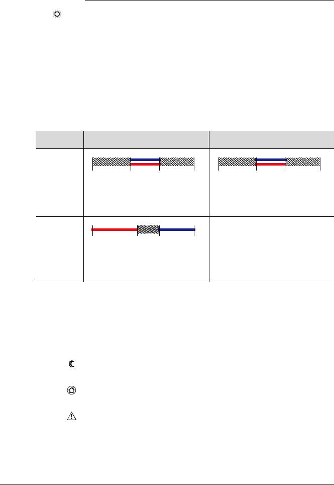
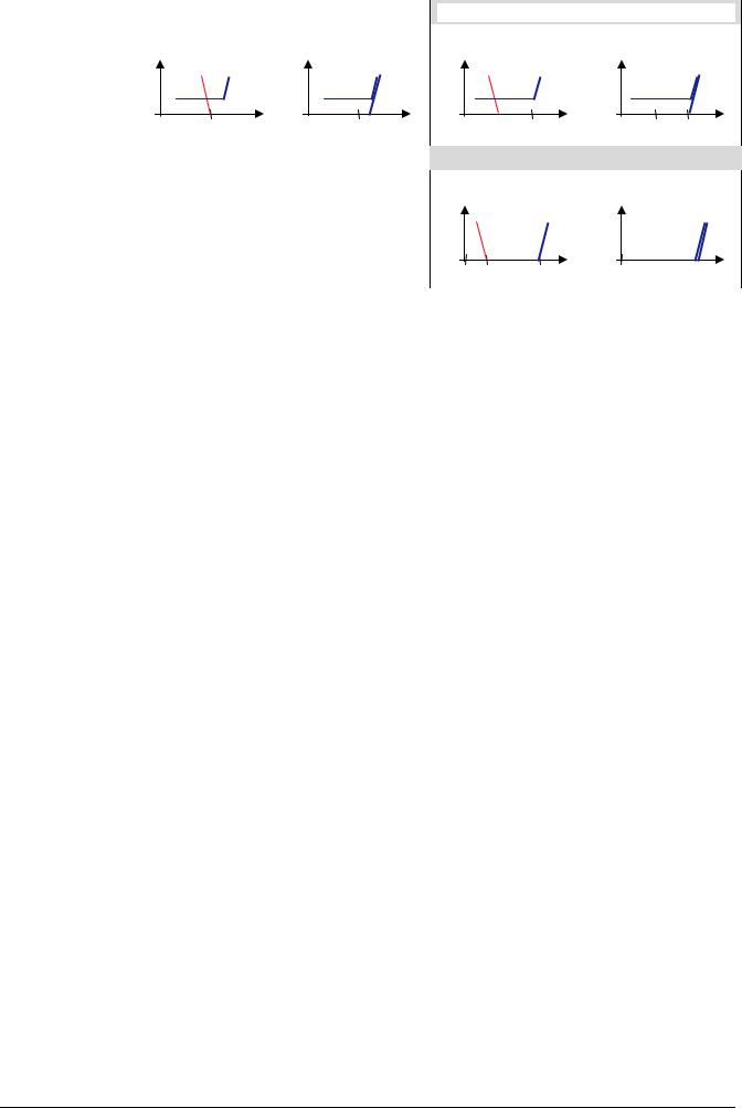
Examples |
Single duct heating or cooling |
|
Single duct cooling |
|
||||
|
|
|
|
|
|
with el. heater / radiator |
|
|
P09 < P10 |
|
|
|
|
|
|
|
|
|
5°C |
18°C |
25°C |
40°C |
5°C |
18°C |
25°C |
40°C |
|
|
P09 |
P10 |
|
|
P09 |
P10 |
|
|
Cooling setpoint adjustable 18…25°C |
Cooling setpoint adjustable 18…25°C |
||||||
|
Heating setpoint adjustable 18…25°C |
Heating setpoint adjustable 18…25°C |
||||||
P09 ≥ P10 |
|
|
|
|
|
Cooling fixed = 25°C (P09) |
|
|
|
5°C |
21°C |
25°C |
40°C |
|
Heating fixed = 21°C (P10) |
|
|
|
|
P10 |
P09 |
|
|
|
|
|
|
Cooling setpoint adjustable 25…40°C |
|
|
|
|
|||
|
Heating setpoint adjustable 5…21°C |
|
|
|
|
|||
Temporary setpoint |
If the “Temporary setpoint function” is enabled via parameter P69, the setpoint |
|||||||
|
adjusted via rotary knob is set back to the Comfort basic setpoint when the |
|
||||||
|
operating mode changes. |
|
|
|
|
|
||
|
The factory setting for the Comfort basic setpoint is 21 °C and can be changed via |
|||||||
|
parameter P08. |
|
|
|
|
|
|
|
Energy Saving mode |
Use control parameters P11 and P12 to adjust the Energy Saving mode setpoints. |
|||||||
|
The heating setpoint is factory-set to 15 °C and to 30 °C for cooling. |
|
||||||
Protection mode |
Use control parameters P65 and P66 to adjust the Protection mode setpoints. |
|||||||
|
The heating setpoint is factory-set to 8 °C (frost protection) and to OFF for cooling. |
|||||||
Caution |
If a setpoint is set to OFF (P65, P66), the thermostat does not maintain the setpoint |
|||||||
|
in the corresponding mode (heating or cooling). |
|
|
|
||||
|
This means no protective heating or cooling function and thus risk of frost in the |
|||||||
|
heating mode or risk of overheat in cooling mode! |
|
|
|||||
10 / 42
Siemens |
RDG100…/RDG110…/RDG140.../RDG160… Basic Documentation |
CE1P3182en |
Building Technologies |
Functions |
28 May 2009 |
4.4Setpoints and sequence
In single-duct changeover applications the Comfort setpoints for heating and cooling sequence are the same (w).
In applications with electrical heater, radiator or heating / cooling coil the Comfort setpoint is at the heating sequence.
The start of the cooling sequence is linked to “Dead-zone” above the Comfort setpoint. The dead zone can be set via parameter P33.
The setpoints for Energy Saving and Protection mode are below the Comfort setpoints (heating) and above the Comfort setpoints (cooling).
They can be set via parameters P11, P12 (Energy Saving) and P65, P66 (Protection).
The control signal for air flow can be limited via parameters P63 and P64. See section 4.8.1.
To simplify the diagram below, only minimum limitation is shown.
|
|
|
|
|
|
|
|
|
wHeatProt |
|
w |
|
wCoolProt |
||||
|
|
wHeatEco |
|
|
wCoolEco |
|||
T[°C]
3181D127
|
|
|
|
|
|
|
Comfort mode |
|
|
|
Energy Saving / Protection mode |
|||||||||||
|
Application |
|
|
Heating mode |
|
|
Cooling mode |
|
|
Heating mode |
|
Cooling mode |
||||||||||
|
|
|
|
Y |
|
|
|
Y |
|
|
Y |
|
|
Y |
|
|||||||
|
Single duct |
|
|
|
|
|
|
|
|
|
|
|
|
|
|
|
|
|
|
|
|
|
|
|
|
|
|
|
|
|
|
|
|
|
|
|
|
WHeatEco T |
|
|
|
|
|
||
|
|
|
|
|
|
|
|
|
|
|
|
|
|
|
|
|
|
|
|
|
|
|
|
|
|
|
|
W |
T |
|
|
W |
T |
|
|
WHeatProt |
|
|
|
WCoolEco |
WCoolProt T |
||||
|
|
|
|
|
|
|
|
|
|
|
|
|
|
|
|
|
|
|
|
|
|
|
|
Single duct |
|
Y |
|
|
|
Y |
|
|
Y |
|
|
Y |
|
||||||||
|
with min/max |
|
|
|
|
|
|
|
|
|
||||||||||||
|
limitation |
|
|
|
|
|
|
|
|
|
|
|
|
|
|
|
|
|
|
|
|
|
|
|
|
|
|
|
|
|
|
|
|
|
|
|
|
|
|
|
|
|
|
||
|
|
|
|
|
|
|
|
|
|
|
|
|
|
|
|
|
|
|
|
|
|
|
|
|
|
|
|
W |
T |
|
|
W |
T |
|
|
WHeatProt |
WHeatEco T |
|
|
WCoolEco |
WCoolProt T |
||||
|
|
|
|
|
|
|
|
|
|
|
|
|
|
|
|
|
|
|
|
|
|
|
|
|
|
|
Comfort mode |
|
Energy Saving |
|
Protection mode |
||||||||
|
Application |
|
|
|
|
|
|
|
|
|
|
|
|
|
|
|
|
Single duct |
|
Y |
|
|
YE |
|
|
YE |
|
|
|
YE |
|||
|
with |
|
|
|
|
|
|
|
Y |
|
|
Y |
||||
|
|
|
|
|
|
|
|
|
|
|
|
|
|
|
|
|
|
electrical |
|
|
|
|
|
|
|
|
|
|
|
|
|
|
|
|
|
|
|
|
|
|
|
|
|
|
|
|
|
|
|
|
|
heater |
|
|
|
|
W |
T |
|
WHeatEco |
WCoolEco |
T |
|
WHeatProt WCoolProtT |
|||
|
|
|
|
|
|
|
|
|
|
|
|
|
|
|
|
|
|
|
|
Y |
|
|
YR |
|
|
YR |
|
|
|
YR |
|||
|
Single duct |
|
|
|
|
|
|
|
Y |
|
|
Y |
||||
|
|
|
|
|
|
|
|
|
|
|
|
|
|
|
|
|
|
with radiator |
|
|
|
|
|
|
|
|
|
|
|
|
|
|
|
|
|
|
|
|
|
|
|
|
|
|
|
|
|
|
|
|
|
|
|
|
|
|
|
|
|
|
|
|
|
|
|
|
|
|
|
|
|
|
|
W |
T |
|
WHeatEco |
WCoolEco |
T |
|
WHeatProt WCoolProtT |
|||
|
|
|
|
|
|
|
|
|
|
|
|
|
|
|
|
|
|
|
11 / 42 |
|
|
|
Siemens |
RDG100, RDG100T, RDG110, RDG140, RDG160 Basic Documentation |
CE1P3182en |
Building Technologies |
Functions |
28 May 2009 |
|
|
|
|
|
|
|
Comfort mode |
|
|
|
|
|
|
|
|
|||||
|
|
|
|
|
|
|
|
|
|
|
Energy Saving mode |
|
||||||||
|
Application |
|
|
|
Heating mode |
|
|
|
Cooling mode |
|
|
Heating mode |
Cooling mode |
|
||||||
|
Single duct |
|
Y |
|
YHC |
|
|
|
Y |
|
YHC |
|
|
|
YHC |
|
YHC |
|
||
|
|
|
|
|
|
|
|
|
|
|
Y |
Y |
|
|||||||
|
with heating / |
|
|
|
|
|
|
|
|
|
|
|
|
|
|
|
|
|
|
|
|
cooling coil |
|
|
|
W |
|
|
|
|
|
W |
|
|
|
|
|
|
|
|
|
|
|
|
|
|
|
|
|
|
|
|
|
|
|
|
|
|
||||
|
|
|
|
T |
|
|
|
T |
|
|
WHeatEco WCoolEco T |
|
WHeatEco WCoolEco T |
|
||||||
|
|
|
|
|
|
|
|
|
|
|
|
|
||||||||
|
|
|
|
|
|
|
|
|
|
|
|
|
|
|
|
|
|
|
|
|
|
|
Protection mode |
|
|||||
|
|
|
|
|
|
|
|
|
|
|
Heating mode |
|
|
Cooling mode |
|
||
|
Y |
YHC |
|
Y |
|
|
YHC |
|
|
|
|
|
|
|
|
||
|
|
|
|
|
|
|
|
|
|
|
|
|
|
|
|
|
|
|
|
WHeatProt WCoolProt T |
|
|
WHeatProt WCoolProt T |
|
||
|
|
|
|
|
|
|
|
|
W=Setpoint in Comfort mode
WHeatEco/Prot = Setpoint heating in Energy Saving or Protection mode
WCoolEco/Prot = Setpoint cooling in Energy Saving or Protection mode
YR = Radiator sequence
YE = El. heater sequence
YHC = Heat/cool coil sequence
12 / 42
Siemens |
RDG100…/RDG110…/RDG140.../RDG160… Basic Documentation |
CE1P3182en |
Building Technologies |
Functions |
28 May 2009 |

4.5Applications overview
The thermostat supports the following applications, which can be configured via DIP switches at the rear of the unit. The control output for the damper actuator is either DC 0…10 V (factory setting) or 3-position (see parameter P47), and for the heating / cooling output ON/OFF, PWM, 3-position or DC 0…10 V.
|
Application |
|
|
|
|
Single-duct |
|
|
|
|
|
|
|
|
|
||
• |
DC 0…10 V damper actuator |
|
|
|
|
|
|
|
|
||
• |
3-position damper actuator |
|
|
||
V M |
|||||
|
|
|
|
|
|
|
|
|
YV |
||
Single-duct with electrical heater |
|
|
|
|
|
|
|
|
|
• DC 0…10 V damper actuator and |
|
|
|
|
|
|
|
|
|
ON/OFF, PWM or 3-position electrical |
|
|
||
V M |
||||
heater |
|
|
|
|
|
|
|
|
|
|
YV |
|||
• 3-position damper actuator and |
|
|||
|
|
|
|
|
DC 0…10 V electrical heater |
|
|
|
|
Single-duct and radiator / floor heating
• DC 0…10 V damper actuator and |
|
|
|
|
|
|
|
|
|
ON/OFF, PWM or 3-position radiator |
|
|
|
|
|
|
|
|
|
|
YV |
|||
• 3-position damper actuator and |
|
|||
|
|
|
|
|
DC 0…10 V radiator |
|
|
|
|
Single-duct heating / cooling coil |
|
|
|
|
|
|
|
|
|
• DC 0…10 V damper actuator and |
|
|
|
|
|
|
|
|
|
ON/OFF, PWM or 3-position heating / |
|
|
||
V M |
||||
cooling |
|
|
|
|
|
YV |
|||
•3-position damper actuator and DC 0…10 V heating /cooling
|
|
|
|
|
|
|
|
|
|
|
|
|
DIP switch |
Control output |
|||||||
|
|
|
|
|
|
|
|
|
|
|
|
|
|
|
|
|
|
|
|
|
DC 0…10 V |
|
|
|
|
|
|
|
|
|
|
|
|
|
ON |
|
|
|
|
|
|
|
|
|
|
|
|
|
|
|
|
|
|
|
|
|
|
|
|
|
|
|
|
|
|
|
|
|
|
|
|
|
|
|
|
|
|
|
OFF |
|
|
|
|
|
|
|
|
|
|
|
|
|
|
|
|
|
|
|
|
|
|
|
|
|
|
|
|
|
|
|
|
|
|
|
|
|
|
|
|
|
|
|
1 |
2 |
3 |
4 |
5 |
|
|
||
|
|
|
|
|
|
|
|
|
|
|
|
|
|
|
|
|
|
|
|
|
3-position |
|
|
|
|
|
|
|
|
|
|
|
|
|
|
|
|
|
|
|
|
|
|
|
|
|
|
|
|
|
|
|
|
|
|
T |
|
|
|
|
|
|
|
|
|
|
|
|
|
|
|
|
|
|
|
|
B1 |
|
|
|
|
|
|
|
|
|
|
|
|
|
|
|
|
|
|
|
|
|
|
|
|
|
|
|
|
|
|
|
DC 0…10 V |
|
|
|
|
|
|
|
|
|
|
|
|
|
|
|
|
|
|
|
|
|
|
|
|
|
|
|
|
|
|
|
|
|
|
|
|
|
|
|
|
|
|
|
|
|
YE |
|
|
|
|
|
|
|
|
|
|
|
|
|
|
||||||
|
|
|
|
|
|
|
|
|
|
|
|
|
ON |
|
|
|
|
|
|
|
|
|
|
|
|
|
|
|
|
|
|
|
|
|
OFF |
|
|
|
|
|
|
|
|
|
|
|
|
|
|
|
|
|
|
|
|
|
|
|
|
|
|
|
|
|
|
|
|
|
|
|
|
|
|
|
|
|
|
|
1 |
2 |
3 |
4 |
5 |
|
ON/OFF, PWM or |
||
|
|
|
|
|
|
|
|
|
|
|
|
|
|
|
|
|
|
|
|
|
|
|
|
|
|
|
|
|
|
|
|
|
|
|
|
|
|
|
|
|
|
|
3-position |
|
|
|
|
|
|
|
|
|
|
|
|
|
|
|
|
|
|
|
|
|
|
|
|
|
|
|
|
|
|
|
|
|
T |
|
|
|
|
|
|
|
|
||
|
|
|
|
|
|
|
|
|
|
|
|
|
|
|
|
|
|
|
|
||
|
|
|
|
|
|
|
|
|
|
|
B1 |
|
|
|
|
|
|
|
|
|
|
|
|
|
|
|
|
|
|
|
|
|
|
|
|
|
|
|
|
|
|
|
DC 0…10 V |
|
|
|
|
|
|
|
|
|
|
|
|
|
|
|
|
|
|
|
|
|
|
|
|
|
|
|
|
|
|
|
|
|
|
|
ON |
|
|
|
|
|
|
|
|
|
|
|
|
|
|
YR |
|
|
|
|
|
OFF |
|
|
|
|
|
|
|
|
|
|
|
|
|
|
|
|
|
|
|
|
|
|
|
|
|
|
|
|
|||
|
|
|
|
|
|
|
|
|
|
|
1 |
2 |
3 |
4 |
5 |
|
ON/OFF, PWM or |
||||
|
|
|
|
|
|
|
|
|
|
|
|
|
|
|
|
|
|
|
|
|
|
|
|
|
|
|
|
|
|
|
|
|
|
|
|
|
|
|
|
|
|
|
3-position |
|
|
|
|
|
|
|
|
|
|
|
|
|
|
|
|
|
|
|
|
|
|
|
|
|
|
|
|
|
|
|
|
|
T |
|
|
|
|
|
|
|
|
||
|
|
|
|
|
|
|
|
|
|
|
|
|
|
|
|
|
|
|
|
||
|
|
|
|
|
|
|
|
|
|
|
B1 |
|
|
|
|
|
|
|
|
|
|
|
|
|
|
|
|
|
|
|
|
|
|
|
|
|
|
|
|
|
|
|
DC 0…10 V |
|
|
|
|
|
|
|
|
|
|
|
|
|
|
|
|
|
|
|
|
|
|
|
|
|
|
|
T |
|
|
|
|
|
|
|
|
|
|
|
|
|
|||
|
|
|
|
|
|
|
|
|
|
|
|
|
|
|
|
|
|
|
|||
|
|
|
|
|
B2 |
|
|
|
|
|
ON |
|
|
|
|
|
|
|
|
||
|
|
|
|
|
|
|
|
|
|
|
|
|
|
|
|
|
|
|
|
|
|
Y1 |
|
|
|
|
|
|
|
|
|
|
|
|
|
|
|
||||||
|
|
|
|
|
|
|
|
|
|
OFF |
|
|
|
|
|
|
|
|
|||
|
|
|
|
|
|
|
|
|
|
1 |
2 |
3 |
4 |
5 |
|
ON/OFF, PWM or |
|||||
|
|
|
|
|
|
|
|
|
|
|
|
|
|
||||||||
|
|
|
|
|
|
|
|
|
|
|
|
|
|
|
|
|
|
|
|
|
|
|
|
|
|
|
|
|
|
|
|
|
|
|
|
|
|
|
|
|
|
|
3-position |
|
|
|
|
|
|
|
|
|
|
|
|
|
|
|
|
|
|
|
|
|
|
|
|
|
|
|
|
|
|
|
|
|
T |
|
|
|
|
|
|
|
|
||
|
|
|
|
|
|
|
|
|
|
|
|
|
|
|
|
|
|
|
|
||
|
|
|
|
|
|
|
|
|
|
|
B1 |
|
|
|
|
|
|
|
|
|
|
|
|
|
|
|
|
|
|
|
|
|
|
|
|
|
|
|
|
|
|
|
|
Key |
Y1 |
Heating or heating/cooling valve actuator |
B1 |
Return air temperature sensor or external |
|
|
|
|
room temperature sensor (optional) |
|
YV |
damper actuator |
B2 |
Changeover sensor (optional) |
|
YE |
Electrical heater |
|
|
|
|
13 / 42 |
|
|
|
Siemens |
RDG100, RDG100T, RDG110, RDG140, RDG160 Basic Documentation |
CE1P3182en |
Building Technologies |
Functions |
28 May 2009 |
Loading...