


 Loading...
PRIMERGY S60
Storage Subsystem
Edition September 2001
Comments… Suggestions… Corrections…
The User Documentation Department would like to know your opinion on this manual. Your feedback helps us to optimize our documentation to suit your individual needs.
Fax forms for sending us your comments are included at the back of the manual.
There you will also find the addresses of the relevant User
Documentation Department
Copyright and Trademarks
Copyright © 2001 Fujitsu Siemens Computers GmbH.
All rights reserved.
Delivery subject to availability; right of technical modifications reserved.
All hardware and software names used are trademarks of their respective manufacturers.
This manual was produced by
cognitas. Gesellschaft für Technik-Dokumentation mbH www.cognitas.de
This manual is printed on paper treated with chlorine-free bleach.
German
English

Contents
1 |
Introduction . . . . . . . . . . . . . . . . . . . . . . . . . . . . 1 |
1.1Target Group . . . . . . . . . . . . . . . . . . . . . . . . . . . . 2
1.2 |
Notation Conventions . |
. . . . . . . . . . . . . . . . . . . . . . |
2 |
1.3 |
Structure of the Manual |
. . . . . . . . . . . . . . . . . . . . . . |
3 |
1.4Technical Data . . . . . . . . . . . . . . . . . . . . . . . . . . . 4
2 |
Important Notes |
. . . . . . . . . . . . . . . . . . . . . . . . . |
7 |
2.1 |
Notes on Safety |
. . . . . . . . . . . . . . . . . . . . . . . . . . |
7 |
2.2Electrostatic Sensitive Device Label . . . . . . . . . . . . . . . . 9
2.3 |
CE certificate . . . . . . . . . . . . . . . . . . . . . . . . . . 10 |
2.4RFI Suppression . . . . . . . . . . . . . . . . . . . . . . . . . 10
2.5FCC notices (Federal Communications Commission) . . . . . . 10
2.6 |
Notes on the Rack Model . . . . . . . . . . . . . . . . . . . . 11 |
2.7Notes on Transportation . . . . . . . . . . . . . . . . . . . . . 11
2.8 |
Environmental Protection . . . . . . . . . . . . . . . . . . . . |
12 |
3 |
Operating and Indicator Elements . . . . . . . . . . . . . . |
15 |
3.1 |
The Front . . . . . . . . . . . . . . . . . . . . . . . . . . . . |
15 |
3.1.1Meaning of the S60 Operating Status LEDs . . . . . . . . . . . 16
3.1.2 |
The Control LEDs for the Hard Disk Drives . . . . . . . . . . . 18 |
3.2The Rear Side . . . . . . . . . . . . . . . . . . . . . . . . . . 20
3.2.1 |
FFx-RAID Controller Module LEDs . . . . . . . . . . . . . . . 20 |
3.2.2Power Supply Unit LEDs . . . . . . . . . . . . . . . . . . . . . 21
3.2.3 |
Power Switch . . . . . . . . . . . . . . . . . . . . . . . . . . 22 |
3.3Fan LED . . . . . . . . . . . . . . . . . . . . . . . . . . . . . 23
4 |
Floorstand Model . . . . . . . . . . . . . . . . . . . . . . . . |
25 |
4.1 |
Open the Housing . . . . . . . . . . . . . . . . . . . . . . . . |
25 |
4.1.1 |
Removing and Mounting the door . . . . . . . . . . . . . . . . |
25 |
4.1.2 |
Removing/Mounting the left Side Cover . . . . . . . . . . . . . |
26 |
5 |
Power Supply . . . . . . . . . . . . . . . . . . . . . . . . . . |
29 |
5.1 |
Power Supply Units . . . . . . . . . . . . . . . . . . . . . . . |
29 |
5.1.1 |
Replacing the Power Supply Unit . . . . . . . . . . . . . . . . |
30 |
6 |
Fan Module . . . . . . . . . . . . . . . . . . . . . . . . . . . |
33 |
6.1Installing/Removing the Fan Module . . . . . . . . . . . . . . . 34
U41221-J-Z156-1-74

Contents
7 |
FC Hard Disk Drives . . . . . . . . . . . . . . . . . . . . . . . 37 |
|
7.1 |
Handling Hard Disk Drives/HDD Modules |
. . . . . . . . . . . . 37 |
7.2 |
Installing/Removing HDD/Dummy Module |
. . . . . . . . . . . . 38 |
7.3Hot Swap for FC HDD Modules . . . . . . . . . . . . . . . . . . 42
7.4Identification Marks and Loop Addresses . . . . . . . . . . . . . 43
8 |
Plug-in Board Modules . . . . . . . . . . . . . . . . . . . . . 45 |
8.1The FFx-RAID Controller Module . . . . . . . . . . . . . . . . . 45
8.1.1 |
Indicators and Connectors |
. |
. |
. |
. . . . . . . . . . . . . . . . |
. |
46 |
8.1.2 |
Switches . . . . . . . . . |
. |
. |
. |
. . . . . . . . . . . . . . . . |
. |
50 |
8.1.3Installing/removing the FFx-RAID controller module . . . . . . . 52
8.1.4Adding a Second FFx-RAID Controller Module . . . . . . . . . . 54
8.1.5The FFx-BBU (Battery Backup Unit) Module . . . . . . . . . . . 55
9 Connections . . . . . . . . . . . . . . . . . . . . . . . . . . . 57
9.1Fibre Channel (FC) Connection . . . . . . . . . . . . . . . . . . 58
9.2Mains Connection . . . . . . . . . . . . . . . . . . . . . . . . . 58
9.3 |
Mains Connection with Phase Redundancy . . . . . . . . . . . 59 |
|
9.4 |
Power connection via UPS . . . . . . . . . . . . . . . . . . . . 60 |
|
10 |
Installation . . . . . . . . . . . . . . . . |
. . . . . . . . . . . . 61 |
10.1 |
Installation Steps . . . . . . . . . . . . . |
. . . . . . . . . . . . 61 |
10.2Unpacking the Storage Subsystem . . . . . . . . . . . . . . . . 62
10.3Setting Up the Floorstand Model . . . . . . . . . . . . . . . . . 62
10.4 |
Mounting the Rack Model . . . . . . . . . . . . . . . . . . . . 63 |
10.4.1Preparing the Slide Rails . . . . . . . . . . . . . . . . . . . . . 64
10.4.2 |
Mounting Slide Rails . . . . . . . . . . . . . . . . . . . . . . . 65 |
10.4.3Mounting the Subsystem . . . . . . . . . . . . . . . . . . . . . 65
10.4.4 |
Routing the Cables . . . . . . . . . . . . . . . . . . . . . . . . 66 |
10.5Connecting and Disconnecting Cables . . . . . . . . . . . . . . 68
10.6 |
Switching the Storage Subsystem ON/OFF |
. . . . |
. |
. |
. |
. |
. |
. |
. 69 |
11 |
Troubleshooting . . . . . . . . . . . . . |
. . . . . |
. |
. |
. |
. |
. |
. |
. 71 |
11.1Problem Solutions and Tips . . . . . . . . . . . . . . . . . . . . 71
11.1.1 |
Power Supply Status Indicator (Front) . . |
. . . . . . . . . . . . 71 |
11.1.1.1 |
Power supply status indicator remains dark |
. . . . . . . . . . . 71 |
11.1.1.2 |
Power supply status indicator lights yellow |
. . . . . . . . . . . . 72 |
11.1.1.3 |
Power supply status indicator lights orange |
. . . . . . . . . . . 72 |
11.1.2 |
Cooling Status . . . . . . . . . . . . . . |
. . . . . . . . . . . . 73 |
11.1.2.1 |
Cooling status LED lights yellow . . . . . |
. . . . . . . . . . . . 73 |
11.1.2.2 |
Cooling status LED lights orange . . . . . |
. . . . . . . . . . . . 73 |
U41221-J-Z156-1-74

Contents
11.1.3Server Management Status . . . . . . . . . . . . . . . . . . . 74
11.1.3.1 |
Server Management Status LED lights permanently . . . . . . |
74 |
11.1.4 |
Storage Subsystem Switches OFF . . . . . . . . . . . . . . . |
75 |
11.1.5 |
System will not boot after Installation of New HDD Modules . . |
75 |
11.1.6HDD READY Indicator does not light up . . . . . . . . . . . . . 75
11.1.7Hard Disk Drives“ dead” on System Start . . . . . . . . . . . . 76
11.1.8 |
Controller reports Added Hard Disk Drive as defective . . . . . |
76 |
Abbreviations . . . . . . . . . . . . . . . . . . . . . . . . . . . . . . . |
77 |
|
Related publications . . . . . . . . . . . . . . . . . . . . . . . . . . . |
81 |
|
Index . . . . . . . . . . . . . . . . . . . . . . . . . . . . . . . . . . . . |
83 |
|
U41221-J-Z156-1-74

1 Introduction
The functionality, mechanics and design of the PRIMERGY S60 storage subsystem are optimally adapted to the PRIMERGY Nxxx server computenodes. It can be used as rack or as floorstand model. In the 19-inch rack, the S60 subsystem occupies three height units.
The PRIMERGY S60 storage subsystem use the fiber-channel technology and can accommodate up to fourteen 1-inch hard disk drives.
The use of fiber-channel technology ensures high transmission speeds over long distances, using a very uncomplicated infrastructure.
Components such as fans, power supply units, hard disk drives and FFx-RAID controller modules (dual controller configuration only) can be replaced with the system running. Redundancy is provided for central components, offering a high degree of data security and reliability.
Server Management/ServerView
For the first step the server management for the PRIMERGY S60 storage subsystem will be ensured by SES (SCSI Enclosure Service).
A optional Remote Service Board (RSB) with more functions can be installed. In this case remote diagnosis is available to the customer or service provider for analysis, remote system configuration and a remote restart - even if the operating system or the hardware fails.
The RSB-module is board which includes a completely independent system. It has a separate operating system with web server and SNMP agents, and can be driven by an external power supply.
The board is installed in the storage subsystem and connected to the HDD backplane.
Further informations is provided in the documentation for the Remote Service Board (see “Related publications” on page 81).
ServerView and the related agents are set up within the group of servers and storage subsystems being monitored. The received information are evaluated by ServerView and processed for display or forwarding to the administrator (manager).
U41221-J-Z156-1-74 |
1 |

Target Group |
Introduction |
IWhen installing PRIMERGY S60 storage subsystems in connection with ServerView please install the ServerStart CD version 4.06 or higher on each of the connected servers.
See ServerView documentation for notes concerning installing and update (see also “Related publications” on page 81).
1.1Target Group
The operating instructions are intended for the person responsible for installing the hardware and correctly operating the system. The operating manual contain all the descriptions which are of importance for commissioning your PRIMERGY S60 storage subsystem in so far as they do not form part of the publication of your server system.
To understand the different expansion options it is necessary to have a knowledge of hardware and data transmission, as well as basic knowledge of the operating system used.
1.2Notation Conventions
Italics |
identifies commands and entries in flow text |
|
|
Bold |
highlights text |
|
|
“Quotation marks” |
indicates references to other chapters or manuals |
|
|
Ê |
identifies an operation that you have to perform. |
|
|
I |
indicates additional information, notes and tips |
|
|
VCAUTION! |
indicates warnings, which, if ignored, will endanger |
your health, the operability of your server or the |
|
|
security of your data |
|
|
2 |
U41221-J-Z156-1-74 |
Introduction |
Structure of the Manual |
1.3Structure of the Manual
The PRIMERGY S60 storage subsystem manual describes how to install and configure the subsystem and perform expansions or upgrades.
You will find further information (see also entries in the chapter “Related publications” on page 81):
●in the “Safety, Warranty and Ergonomics” manual
●in the documentation on the PRIMERGY server This manual consists of the following chapters:
●Important notes
This chapter contains instructions on the safe operation of your storage subsystem as well as information about environmental protection.
●Operating and indicator elements
This chapter gives a detailed description of the operating panel and the connecting elements on the rear panel of the storage subsystem.
●Floorstand model
This part of the manual describes how opening and closing the floorstand model housing.
●Power supply
This part of the manual describes the power supply units and their power supply. Fitting and removing power supply units is also described in detail.
●Fan module
This part of the manual describes the fitting and removal of the fan module.
●FC drives
This chapter describes in detail how the hot swappable drives must be dealt with.
●Plug-in board modules
This chapter describes the FFx-RAID controller and its mounting and removal.
●Connections
This chapter describes the FC and the mains connection.
The possibilities of supplying the storage subsystem with mains voltage are also described.
U41221-J-Z156-1-74 |
3 |

Technical Data |
Introduction |
●Configurations
This part of the manual gives configuration examples.
●Installation
The activities needed to install and commission the storage subsystem are described.
●Troubleshooting
This chapter contains advice on solving problems that occur on commissioning or during the operation of the storage subsystem.
1.4Technical Data
Electrical Characteristics
Rated voltage |
|
100 V - 240 V |
|
|
|
|
|
Tolerance of the rated voltage |
+6 % / -10 % |
||
|
|
|
|
Rated frequency |
|
50 Hz / 60 Hz |
|
|
|
|
|
Rated current |
|
max. 1.3 A at 240 V |
|
|
|
max. 3.1 A at 100 V |
|
|
|
|
|
Power consumption |
|
|
|
|
|
|
|
Active power (= heat transfer) |
max. 305 W |
||
|
|
|
|
Apparent power |
|
max. 310 VA |
|
|
|
|
|
Power factor (PF) |
|
0.95-0.99 |
|
|
|
|
|
|
|
|
|
Dimensions and |
Floorstand model |
Rack model |
|
Weight |
|
|
|
|
|
|
|
Height |
481mm |
|
133 mm |
|
|
|
|
Width |
200 mm without legs |
483 mm |
|
|
280 mm with legs |
|
|
|
|
|
|
Depth |
692 mm |
|
646 mm |
|
|
|
|
Weight |
max. 32 kg |
|
max. 30 kg |
|
|
|
|
4 |
U41221-J-Z156-1-74 |

Introduction |
Technical Data |
Environmental Conditions (according to DIN EN 60721-3-x)
Climate/operation (class 3K2):
|
|
|
|
|
|
|
Temperature |
|
15 °C to 35°C |
|
|
|
|
|
|
|
|
|
|
|
Relative humidity |
|
5% to 85% |
|
|
|
|
|
|
|
|
|
|
|
altitude (NN) |
|
max. 3048 m (10000 ft.) |
|
|||
|
|
|
|
|
|
|
Climate/transport (class 2K2): |
|
|
|
|
|
|
|
|
|
|
|
|
|
Temperature |
|
-25°C to 60°C |
|
|
|
|
|
|
|
|
|
|
|
Relative humidity |
|
15% to 98% |
|
|
|
|
|
|
|
|
|
|
|
altitude (NN) |
|
max. 15240 m (50000 ft.) |
|
|||
|
|
|
|
|
|
|
Mechanical environmental conditions |
|
|
|
|
||
|
|
|
|
|
|
|
Operation |
|
Class 3M2 |
|
|
|
|
|
|
|
|
|
|
|
Transport |
|
Class 2M1 |
|
|
|
|
|
|
|
|
|
|
|
|
|
|
|
|
|
|
Standards Complied With |
|
|
|
|
|
|
|
|
|
|
|
|
|
Product safety and ergonomics |
IEC 60950 (DIN EN 60950), UL 1950, |
|
|
|||
|
CSA 950, ZH1/618 |
|
|
|
|
|
|
|
|
|
|
|
|
Electromagnetic compatibility |
|
|
|
|
|
|
|
|
|
|
|
|
|
Emitted interference |
EN 55022, class B; FCC part 15, class A |
|
|
|||
|
|
|
|
|
|
|
Noise immunity |
EN 50082-1 |
|
|
|
|
|
|
|
|
|
|
|
|
CE label |
Low voltage guideline |
|
|
|||
|
LVD 73/23/EEC |
|
|
|
|
|
|
EMC guideline 89/339/EWG |
|
|
|||
|
|
|
|
|
|
|
Approval certification |
GS, CSA NRTL/C, CB certificate |
|
|
|||
|
|
|
|
|
|
|
|
|
|
|
|
||
Noise Development (ISO 9296) |
Operation |
Idle |
|
|
|
|
|
|
|
|
|
||
Sound level (LWAd) |
max. 7.0 B |
max. 6.2 B |
|
|
|
|
Workstation-related |
max. 56 dB(A) |
max. 46 dB(A) |
|
|
|
|
sound pressure level (LpAm) |
|
|
|
|
|
|
|
|
|
|
|
||
Maintenance Areas and Ventilation Distances |
|
|
|
|
||
|
|
|
|
|||
Floorstand model |
Rear 400 mm, left 1200 mm * |
|
||||
|
|
|
|
|||
Rack model |
Specified by the 19“ rack |
|
||||
|
|
|
|
|
|
|
*The area on the left need not always be kept open. However, it must be possible to clear it without too much effort.
U41221-J-Z156-1-74 |
5 |

2 Important Notes
2.1Notes on Safety
In this section you will find information that you must note when using the storage subsystem.
This device complies with the relevant safety standards for IT equipment, including electronic office machines, intended for use in the office environment.
IYou will also find the following safety instructions in the manual entitled “Safety, Warranty and Ergonomics“ which also includes other notes on guarantee and ergonomics. Also pay attention to the notes in the manual of the connected PRIMERGY system.
If you have any questions relating to setting up and operating your system in the environment where you intend to use it, please consult our service organization.
VCAUTION!
●The actions described in these instructions should only be performed by technicians, service personnel or technical specialists. Equipment repairs should only be performed by qualified staff. Any failure to observe the guidelines in this manual could expose the user to risks (electric shock, fire hazards) and could also damage the equipment. Note that any unauthorized opening of the device will result in the invalidation of the warranty and exclusion from all liability.
●Transport the device in its original packaging or in other suitable packaging which will protect it against shock or impact.
●Read the notes on environmental conditions in section “Technical Data” on page 4 before setting up and operating the device.
●If the device is brought in from a cold environment, condensation may form both inside and on the outside of the machine.
Wait until the device has acclimatized to room temperature and is absolutely dry before starting it up. Material damage may be caused to the device if this requirement is not observed.
U41221-J-Z156-1-74 |
7 |

Notes on Safety |
Important Notes |
VCAUTION!
●Check that the rated voltage specified on the device's ID plate is the same as the local line voltage.
●The device must only be connected to a properly grounded wall outlet (the device is fitted with a tested and approved power cable).
●Make sure that the protective grounded outlet of the building’s wiring system is freely accessible.
●Switching off the device does not cut off the supply of power. To do this you must remove the power plugs.
●Before opening the unit, switch off the device and then pull out the power plugs.
●Route the cables in such a way that they do not form a potential hazard (make sure no-one can trip over them) and that they cannot be damaged. When connecting up a device, refer to the relevant notes in this manual.
●Never connect or disconnect data transmission lines during a storm (lightning hazard).
●Systems which comprise a number of cabinets must use a separate fused socket for each cabinet.
●The system unit and the directly connected external storage subsystems should be connected to the same power supply distributor. Otherwise you run the risk of losing data if, for example, the central processing unit is still running but the storage subsystem has failed during a power failure.
●Make sure that no objects (such as bracelets or paper clips) fall into or liquids spill into the device (risk of electric shock or short circuit).
●In emergencies (e.g. damage to housings, power cords or controls or ingress of liquids or foreign bodies), immediately power down the device, pull out the power plugs and notify your service department.
●Note that proper operation of the system (in accordance with IEC 60950/DIN EN 60950) is guaranteed only if slot covers are installed on all vacant slots and/or dummies on all vacant bays and the housing cover is fitted (cooling, fire protection, RFI suppression).
8 |
U41221-J-Z156-1-74 |
Important Notes |
Electrostatic Sensitive Device Label |
2.2Electrostatic Sensitive Device Label
Electrostatic-sensitive components may be identified by the following sticker:
Figure 1: Electrostatic Sensitive Device (ESD) sticker
You must follow the instructions below when handling modules containing electrostatic-sensitive components
ÊDischarge static electricity from your body (for example by touching a grounded metal object) before handling modules containing electrostaticsensitive components.
ÊThe equipment and tools you use must be free of static charge.
ÊRemove the power plug before installing or removing modules containing electrostatic-sensitive components.
ÊOnly hold modules containing electrostatic-sensitive components by their edges.
ÊDo not touch any of the pins or track conductors on a module containing electrostatic-sensitive components.
ÊUse a grounding strap designed for the purpose, to connect you to the system unit as you install the modules.
ÊPlace all components on a static-safe base.
IAn exhaustive description of the handling of modules containing electro- static-sensitive components can be found in “Guidelines on handling electrostatic sensitive devices and modules (ESD)” or “ITS Circular 4/95”.
U41221-J-Z156-1-74 |
9 |

CE certificate |
Important Notes |
2.3CE certificate
The shipped version of this device complies with the requirements of the EEC directives 89/336/EEC “Electromagnetic compatibility” and 73/23/EEC “Low voltage directive”. The device therefore qualifies for the CE certificate (CE=Communauté Européenne).
2.4RFI Suppression
All other equipment which is connected to this product must also have radio noise suppression in accordance with EC Guideline 89/336/EWG.
Products which meet this requirement are accompanied by a certificate to that effect issued by the manufacturer and/or bear the CE mark. Products which do not meet this requirement may be operated only with the special permission of the BZT (Bundesamt für Zulassungen in der Telekommunikation).
2.5FCC notices (Federal Communications Commission)
Class A digital device
This equipment has been tested and found to comply with the limits for a Class A digital device, pursuant to part 15 of the FCC Rules. These limits are designed to provide reasonable protection against harmful interference when the equipment is operated in a commercial environment. This equipment generates, uses, and can radiate radio frequency energy and, if not installed and used in accordance with the instruction manual, may cause harmful interference to radio communications. Operation of this equipment in a residential area is likely to cause harmful interference in which case the user will be required to correct the interference at his own expense.
10 |
U41221-J-Z156-1-74 |

Important Notes |
Notes on the Rack Model |
2.6Notes on the Rack Model
●For safety reasons, at least two people are required to install the rack model because of its weight and size.
●When connecting and disconnecting cables, observe the notes in the documentation for your PRIMERGY system and the comments in the “Important notes” chapter in the technical manual supplied with the rack.
●Ensure that the anti-tilt bracket is correctly mounted when you set up the rack.
●For safety reasons, no more than one unit may be withdrawn from the rack at any one time during installation and maintenance work.
●If more than one unit is withdrawn from the rack at any one time, there is a danger that the rack will tilt forward.
●The connection of the rack to the mains voltage must be installed by an authorized specialist (electrician).
2.7Notes on Transportation
ITransport the storage subsystem in its original packaging or in other suitable packaging which will protect it against shock or impact.
Do not unpack it until all transport maneuvers are completed.
If you need to lift or transport the storage subsystem, ask someone to help you.
U41221-J-Z156-1-74 |
11 |

Environmental Protection |
Important Notes |
2.8Environmental Protection
Environmentally friendly product design and development
This product has been designed in accordance with the Fujitsu Siemens Computers standard for “environmentally friendly product design and development”.
This means that the designers have taken into account important criteria such as durability, selection of materials and coding, emissions, packaging, the ease with which the product can be dismantled and the extent to which it can be recycled.
This saves resources and thus reduces the harm done to the environment.
Notes on saving energy
Devices that do not have to be on permanently should not be switched on until they need to be used and should be switched off during long breaks and on completion of work
Notes on packaging
We recommend that you do not throw away the original packaging in case you need it later for transportation. If possible, devices should be transported in their original packaging.
Notes on dealing with consumables
Please dispose of batteries in accordance with local regulations.
Notes on labeling plastic housing parts
Please avoid attaching your own labels to plastic housing parts wherever possible, since this makes it difficult to recycle them.
12 |
U41221-J-Z156-1-74 |
Important Notes |
Environmental Protection |
Take-back, recycling and disposal
For details on take-back and reuse of devices and consumables within Europe, contact your Fujitsu Siemens Computers branch office/subsidiary or our recycling center in Paderborn:
Fujitsu Siemens Computers
Recycling Center
D-33106 Paderborn
Tel. ++49 5251 8180-10
Fax ++49 5251 8180-15
Further information on environmental protection
The Fujitsu Siemens Computers representative for environmental protection will be happy to answer any further questions you may have concerning environmental protection.
Fujitsu Siemens Computers
Referat Umweltschutz
Werner-von-Siemens-Straße 6
D-86159 Augsburg
Tel. ++49 821 804-2386
Fax ++49 821 804-2706
U41221-J-Z156-1-74 |
13 |

3 Operating and Indicator Elements
This section describes the position and meaning of the operating and indicator elements on the PRIMERGY S60 storage subsystem.
3.1The Front
You can see the following indicator elements on the front of the PRIMERGY S60 storage subsystem
●The three operating status LEDs which indicate the power supply status, the cooling status and the server management status.
●Control LEDs for the hard disk drives (two LEDs on each of the HDD modules).
IThere is a HDD Ready and a HDD Status LED for each of the 14 possible hard disk drives.
U41221-J-Z156-1-74 |
15 |
The Front |
Operating and Indicator Elements |
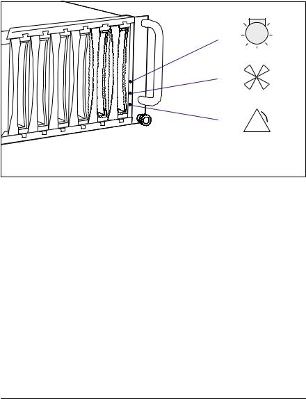
3.1.1Meaning of the S60 Operating Status LEDs
The state of the status LEDs located on the HDD backplane is transmitted by optical waveguides so that the power supply status, the cooling status and the server management status are indicated on the front of the storage subsystem.
1 |
|
2 |
|
3 |
! |
Figure 2: Operating Status LEDs and Icons on the Front of the Rack Model
(1)Power supply status
(2)Cooling status
(3)Server management status
VCAUTION!
In order to guarantee the server management for the PRIMERGY S60 storage subsystem over SES (SCSI Enclosure Service), at least one of the two first HDD modules (see also section “Identification Marks and Loop Addresses” on page 43) must be installed.
IFault clearing instructions can be found in the chapter “Troubleshooting” on page 71 of this manual.
16 |
U41221-J-Z156-1-74 |

Operating and Indicator Elements |
The Front |
|
||
|
|
|
|
|
Optical Waveguide |
Color |
Meaning |
|
|
|
|
|
|
|
Power supply status |
none |
No mains voltage present. |
|
|
|
|
|
|
|
|
green |
POWER OK |
|
|
|
|
Equipment switched ON, all installed |
|
|
|
|
power supply units OK. |
|
|
|
|
|
|
|
|
yellow |
POWER WARNING |
|
|
|
|
|||
|
|
One power supply unit has failed. |
|
|
|
|
|
|
|
|
orange |
STANDBY |
|
|
|
|
Equipment switched OFF, mains voltage |
|
|
|
|
present. |
|
|
|
|
|
|
|
Cooling status |
green |
Cooling OK |
|
|
VCAUTION! |
|
All installed fans and the interior temper- |
|
|
|
ature are OK. |
|
|
|
The PRIMERGY S60 |
yellow |
Fan warning |
|
|
|
One fan has failed. |
|
|
|
storage subsystem |
|
|
|
|
|
The temperature is OK. |
|
|
|
(without Remote Service |
|
|
|
|
|
|
|
|
|
orange |
Cooling fault |
|
|
|
Board) switches OFF at |
|
|
||
|
All the fans have failed or the interior |
|
|
|
an interior temperature of |
|
|
|
|
|
temperature exceeds the permissible |
|
|
|
55°C (see section |
|
|
|
|
|
values. |
|
|
|
“Cooling status LED lights |
|
|
|
|
|
|
|
|
|
orange” on page 73). |
|
|
|
|
|
|
|
|
|
Server management |
none |
No status indication |
|
|
status (global SES |
|
|
|
|
orange |
Identification indication |
|
|
|
indicator) |
|
|
||
|
(can be activated manually from |
|
|
|
|
|
|
|
|
|
|
ServerView). |
|
|
|
|
For troubleshooting see section “Server |
|
|
|
|
Management Status LED lights perma- |
|
|
|
|
nently” on page 74. |
|
|
|
|
|
|
|
Table 1: Meaning of the Operating Status LEDs Indication |
|
|||
U41221-J-Z156-1-74 |
17 |

The Front |
Operating and Indicator Elements |
3.1.2The Control LEDs for the Hard Disk Drives
HDDREADY |
HDDSTATUS |
Figure 3: Symbols of the Control LEDs of the Hard Disk Drives
(HDD READY) Operating indication of the hard disk drive.
This LED is driven by the hard disk drive itself.
(HDD STATUS) Status indication of the hard disk drive.
This dual-color (yellow/orange) LED is set by the hard disk drive itself (yellow indicator) or by the SES controller (orange indicator).
18 |
U41221-J-Z156-1-74 |

Operating and Indicator Elements |
The Front |
|
|
||
|
|
|
|
|
|
LED |
Indication |
Meaning |
|
|
|
|
|
|
|
|
|
HDD |
OFF |
The associated drive is not (correctly) |
|
|
|
READY |
|
inserted or it is spun down and it is not |
|
|
|
|
|
being accessed. |
|
|
|
|
|
|
|
|
|
|
OFF |
The associated drive is spun down. The |
|
|
|
|
green intermittent |
drive is being accessed. |
|
|
|
|
flashes |
|
|
|
|
|
|
|
|
|
|
|
|
|
|
|
|
|
ON |
The associated drive is spun up and ready. |
|
|
|
|
green permanently on |
The drive is not being accessed or hot |
|
|
|
|
|
spare drive. |
|
|
|
|
|
|
|
|
|
|
ON |
The associated drive is spun up and ready. |
|
|
|
|
green intermittent |
The drive is being accessed. |
|
|
|
|
flashes |
|
|
|
|
|
|
|
|
|
|
|
green, |
The associated drive is spinning up or |
|
|
|
|
flashes steadily |
down (“prepare to remove” command: ca. |
|
|
|
|
|
10 sec. flashes quickly 3 times per sec., |
|
|
|
|
|
followed from slowly flashes in 3 sec. |
|
|
|
|
|
interval; see also section “Hot Swap for FC |
|
|
|
|
|
HDD Modules” on page 42). |
|
|
|
|
|
|
|
|
|
HDD |
OFF |
There is no hard disk fault. |
|
|
|
STATUS |
|
|
|
|
|
yellow, |
HDD error occurred. |
|
|
|
|
|
permanently on |
|
|
|
|
|
|
|
|
|
|
|
orange, |
Drive identification. |
|
|
|
|
flashes quickly |
|
|
|
|
|
|
|
|
|
|
|
orange, |
– Drive rebuild: all drives belonging to the |
|
|
|
|
flashes quickly |
pack blink synchronously. |
|
|
|
|
|
– Error message from controller: |
|
|
|
|
|
Critical LUN (Logical Unit Number) |
|
|
|
|
|
– A drives was set on “Make Offline” and |
|
|
|
|
|
the remaining HDD modules flash |
|
|
|
|
|
quickly. |
|
|
|
|
|
|
|
|
|
|
orange, |
“Make Offline” state for the selected HDD |
|
|
|
|
permanently on |
modules. |
|
|
|
|
|
|
|
|
|
Table 2: Meaning of the HDD Control LEDs Indication
U41221-J-Z156-1-74 |
19 |
The Rear Side |
Operating and Indicator Elements |
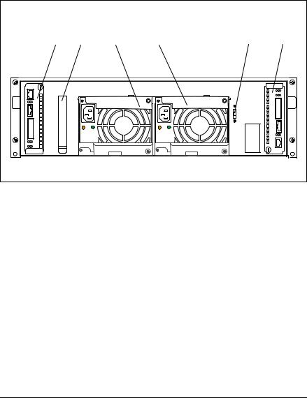
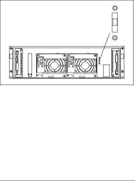
3.2The Rear Side
On the rear side of the PRIMERGY S60 storage subsystem there are the status LEDs for the FFx-RAID controller module(s) and for the power supply units. Also the power switch is placed on this side.
1 |
6 |
2 |
3 |
4 |
5 |
Figure 4: Rear View of the PRIMERGY S60 Storage Subsystem
(1)FFx-RAID controller module 1
(2, 3) Power supply units
(4)Power switch
(5)FFx-RAID controller module 0 (default)
(6)Location for the optional Remote Service Board
3.2.1FFx-RAID Controller Module LEDs
The status LEDs are located on the connection panel of the FFx-RAID controller module. For description see section “The FFx-RAID Controller Module” on page 45.
20 |
U41221-J-Z156-1-74 |
Operating and Indicator Elements |
The Rear Side |
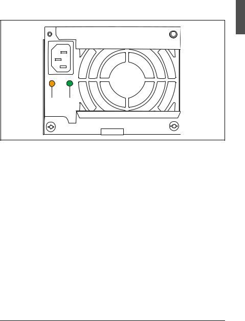
3.2.2Power Supply Unit LEDs
On the connecting side of the power supply units there are two LEDs that indicate the status of the power supply units:
1 |
2 |
Figure 5: The Power Supply Unit LEDs
(1)Fault indication (amber LED)
(2)Operating indication (green LED)
Fault |
Operating |
Status of the power supply unit |
indication (1) |
indication (2) |
|
(amber LED) |
(green LED) |
|
|
|
|
OFF |
OFF |
No AC voltage present. |
|
|
|
OFF |
flashing |
AC voltage present; standby outputs |
|
|
ready. |
|
|
|
OFF |
ON |
DC outputs ready. Power supply unit |
|
|
operational. |
|
|
|
ON |
OFF |
No AC voltage present for this power |
|
|
supply unit or power supply unit has |
|
|
failed. |
|
|
|
flashing |
ON |
Current limiting. |
|
|
|
Table 3: Meaning of the Power Supply Unit LEDs
U41221-J-Z156-1-74 |
21 |
The Rear Side |
Operating and Indicator Elements |
3.2.3Power Switch
The power switch is located also on the rear of the PRIMERGY S60 storage subsystem. It is a slide switch with three possible settings.
I |
R |
O |
Figure 6: Power Switch on the Rear of the PRIMERGY S60 Storage Subsystem
Position |
Function |
Description |
|
|
|
(I) |
local ON |
The storage subsystem is switched ON permanently |
|
|
and is connected directly to the mains (default |
|
|
setting). |
|
|
|
(R) |
The operating mode (on/off) is controlled via the Remote Service |
|
|
Board. In this default setting, the storage subsystem is switched |
|
|
on and off simultaneously with the server. If two servers are |
|
|
connected, it remains active as long as one of the servers is |
|
|
switched on. |
|
|
|
|
(O) |
OFF |
The storage subsystem is switched OFF permanently. |
|
|
|
Table 4: Possible Settings of the Power Switch
22 |
U41221-J-Z156-1-74 |
Loading...