


OPERATING MANUAL MODE D’EMPLOI MANUAL DE FUNCIONAMIENTO
OPERATING MANUAL
AIR CONDITIONER
REMOTE CONTROLLER (WIRED TYPE)
Remote Controller
UTB-UUB
 Français English
SU MO TU WE TH FR SA |
Español |
|||
|
||||
AM |
|
|
|
|
PM |
|
|
|
|
3 |
6 |
9 |
12 15 18 21 |
|
KEEP THIS MANUAL
FOR FUTURE REFERENCE
FUJITSU GENERAL LIMITED |
P/N9373329039-03 |
CONTENTS
SAFETY PRECAUTIONS................................................ |
1 |
NAME OF PARTS ........................................................... |
1 |
FUNCTION INFORMATION ........................................... |
2 |
PREPARATORY OPERATION ......................................... |
3 |
OPERATION ................................................................... |
3 |
ON/OFF TIMER............................................................... |
5 |
WEEKLY TIMER ............................................................. |
6 |
TEMPERATURE SET BACK TIMER ............................... |
8 |
SELF-DIAGNOSIS .......................................................... |
9 |
OPERATING TIPS ........................................................... |
9 |
SPECIFICATIONS ......................................................... |
10 |
TROUBLESHOOTING .................................................. |
10 |
SAFETY PRECAUTIONS
●Before using the appliance, read these “PRECAUTIONS” thoroughly and operate in the correct way.
●The instructions in this section all relate to safety; be sure to maintain safe operating conditions.
DANGER! |
This mark indicates procedures which, if improperly performed, are most likely to result in the death of |
|
or serious injury to the user or service personnel. |
||
|
||
|
|
•Do not attempt to install this controller by yourself.
•This controller contains no user-serviceable parts. Always consult authorized service personnel for repairs.
•When moving, consult authorized service personnel for disconnection and installation of the controller.
•If a problem (burning smell, etc.) occurs, turn off the electrical breaker immediately to stop operation, and then consult authorized service personnel.
This mark indicates procedures which, if improperly performed, might lead to the death or serious  WARNING! injury of the user.
This mark indicates procedures which, if improperly performed, might possibly result in personal harm  CAUTION! to the user, or damage to property.
•Do not expose the controller directly to water.
•Do not operate the controller with wet hands.
•Do not touch the switches with sharp objects.
•Always turn off the electrical breaker whenever cleaning the controller, the air conditioner or the air filter.
•Check the condition of the installation stand for damage.
•Ensure that any electronic equipment is at least one metre away from the controller.
•Avoid installing the controller near a fireplace or other heating apparatus.
•When installing the controller, take precautions to prevent access by infants.
•Do not use inflammable gases near the controller.
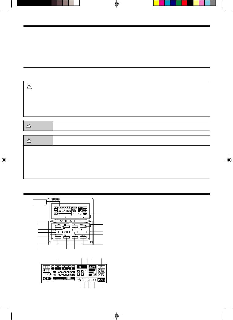
NAME OF PARTS
Display |
|
|
|
|
|
SU MO TU |
WE TH |
FR SA |
|
||
3 |
6 |
9 |
12 15 18 21 |
E |
|
2 |
|
|
|
|
1 |
7 |
|
DAY |
|
|
3 |
|
8 |
CLOCK ADJUST |
DAY OFF |
ENERGY |
THERMO |
4 |
|
SET BACK |
||||||
|
SAVE |
SENSOR |
5 |
|||
9 |
|
|
|
|
||
|
|
|
|
6 |
||
0 |
DELETE SET |
|
|
|||
|
|
|
|
|
||
A |
|
|
|
|
C |
|
B |
|
|
|
|
D |
|
Display panel
F I J H G
SU |
MO |
TU |
WE TH FR SA |
|
|
3 |
6 |
9 |
12 15 18 21 |
O N L M K
1 Start/Stop Button
2 Set Temperature Button
3 Master Control Button
4 Fan Control Button
5 THERMO SENSOR Button
6 ENERGY SAVE Button
7 Timer Mode (CLOCK ADJUST) Button
8 DAY (DAY OFF) Button
9 SET BACK Button
0 Set Time Button
A DELETE Button B SET Button
C Horizontal airflow direction and swing Button D Vertical airflow direction and swing Button E Operation Lamp
F Timer and Clock Display
G Operation Mode Display H Fan Speed Display
I Operation Lock Display J Temperature Display K Defrost Display
L Vertical Swing Display M Horizontal Swing Display N Thermo Sensor Display O Energy Save Display
En-1
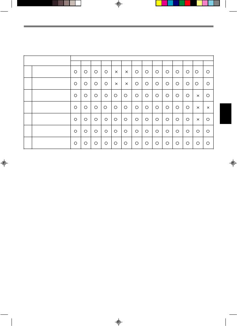
FUNCTION INFORMATION
Depending on the indoor unit model, some buttons on this remote controller cannot be used and some functions are restricted.
Refer to the following table for the buttons that can be used for each model.
 : Button can be operated
 : Button cannot be operated
Button numbers (refer to page 1)
|
Model |
1 2 3 4 5 6 7 8 9 0 A B C D |
||
|
|
|||
*1 |
Wall Mounted Type |
|
|
*7 |
*2 |
|
|
||
(I.A.Q. Model) |
|
|
||
*3 |
|
|
|
|
|
|
|
|
|
*2 |
Wall Mounted Type |
|
|
*7 |
*3 |
|
|
||
|
|
|
|
|
|
Wall Mounted Type |
|
*5 |
*6 |
|
(AIRSTAGE Model) |
|
||
|
|
|
|
|
|
Duct type |
*4 |
*5 |
*6 |
|
Cassette Type |
|
*5 |
*6 |
|
Floor/Ceiling |
|
*5 |
*6 |
|
Universal Type |
|
||
|
|
|
|
|
|
Ceiling Wall Type |
|
*5 |
*6 |
If a button indicated with “ ” is pressed, the operation lock display (I on page 1) flashes, but the air conditioner will not respond.
*1: Air clean operation is always on during air conditioner operation and cannot be turned off.
*2: If the wired remote controller is connected to the indoor unit, a wireless remote controller cannot be used. *3: Before connecting the remote controller, the remote controller cord must be modified.
*4: The fan speed cannot be changed for some large, duct-type indoor units.
*5: This button cannot be operated for the AIRSTAGE S-series remote controllers.
*6: This button cannot be operated for the AIRSTAGE J-series and V-series remote controllers.
*7: This button cannot be operated if the indoor unit has manually-operated horizontal airflow direction louvers.
En-2

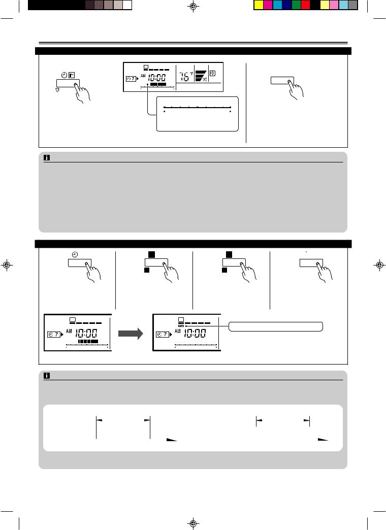
PREPARATORY OPERATION
To set the current day and time
1 |
|
2 |
DAY |
Press the DAY button and select the current day. |
|||||
|
|
||||||||
CLOCK ADJUST |
DAY OFF |
A appears around the selected day. |
|
||||||
Press the TIMER MODE button for 2 |
|
SU |
MO |
TU |
WE |
TH |
FR |
SA |
|
seconds or more. The time display on |
|
|
|
|
|
|
|
|
|
the remote controller will flash. |
|
|
|
|
|
|
|
|
|
3 |
SU MO TU WE TH FR SA |
|
ex. Monday, 10:00 A.M. Press the SET TIME buttons to set the current time.
Press repeatedly to adjust the current time in 1-minute increments. Press and hold to adjust the current time in 10-minute increments.
 CLOCK ADJUST
Press again to end.
OPERATION
Instructions related to heating are applicable to “HEAT PUMP MODELS” and “HEAT RECOVERY MODELS” only.
To start/stop operation
Press the START/STOP button.
Operation lamp
Air conditioner ON: Lit brightly
Air conditioner OFF: Not lit
To set the operation mode
● Operation mode setting Press the MASTER CONTROL button to set the operation mode. If DRY is selected, the fan speed will be set to AUTO.
AUTO |
COOL |
DRY |
FAN |
HEAT |
*AUTO and FAN cannot be selected for “HEAT PUMP MODELS.”
●Room temperature setting Press the SET TEMPERATURE buttons to set the room temperature.
|
|
Temperature setting range |
|
|
|
|
|
AUTO ............................................................ |
|
|
64 to 88 °F |
|
|
COOL/DRY .................................................... |
|
|
64 to 88 °F |
|
|
HEAT ............................................................. |
|
|
48, 52, 56, or 60 to 88 °F* |
Lower |
Raise |
* Room temperatures as low as 48, 52, and 56 °F cannot be set depending on the |
|||
|
|
model. |
|
|
|
● Fan speed setting |
Press the FAN CONTROL button to set the fan speed. |
||||
|
|
AUTO |
HIGH |
MED |
LOW |
● Energy save setting
ENERGY
SAVE
Press the ENERGY SAVE button to start or stop the energysaving air conditioner operation.
*The energy save air conditioner operation is not available depending on the model.
En-3
OPERATION
To set the operation mode
● Vertical air direction adjustment (Swing operation)
|
|
|
|
|
* Press the START/STOP button to start the air conditioner, and then proceed as |
|
|
|
|
|
|
|
|
|
|
|
follows. |
|
|
|
|
|
Press the VERTICAL AIRFLOW DIRECTION button to adjust the direction of the verti- |
|
|
|
|
|
cal airflow. To set the swing operation, press the VERTICAL AIRFLOW DIRECTION |
|
|
|
|
|
|
|
|
|
|
|
button for more than 2 seconds. (Stop the setting by pressing for more than 2 sec- |
|
|
|
|
|
|
ex. Vertical swing operation |
onds again.) |
||||
● Horizontal air direction adjustment (Swing operation)
* Press the START/STOP button to start the air conditioner, and then proceed as
follows.
Press the HORIZONTAL AIRFLOW DIRECTION button to adjust the direction of the horizontal airflow. To set the swing operation, press the HORIZONTAL AIRFLOW DIRECTION button for more than 2 seconds. (Stop the setting by pressing for more
ex. Horizontal swing operation than 2 seconds again.)
NOTES
(1)• Always use the remote controller’s AIRFLOW DIRECTION button. Attempting to move the air direction louvers manually could result in improper operation; in this case,
stop operation and restart.
The flaps should begin to operate properly again.
•During cooling operation, do not set the vertical airflow direction louver in the downward position for an extended period. Water vapor may condense near the outlet port and drops of water may drip from the air conditioner.
(2)• The range of swing is relative to the currently set airflow direction.
•The SWING operation may stop temporarily when the air conditioner’s fan is not operating, or when operating at very low speeds.
(3)The swing operation is not available depending on the model. Please refer to the operating manual for the indoor unit.
<Vertical airflow swing operation>
Airflow direction Range of swing
11 to 3
22 to 4
32 to 4
41 to 4 (All range)
<Horizontal airflow swing operation>
Airflow direction Range of swing
11 to 5 (All range)
21 to 3
32 to 4
43 to 5
51 to 5 (All range)
1
2
3
4
1 2 3 4 5
IMPORTANT: Depending on the indoor unit model, the actual adjustment ranges of the airflow direction may be different from the ranges listed in the tables above. For more information, refer to the operating manual of the indoor unit.
En-4
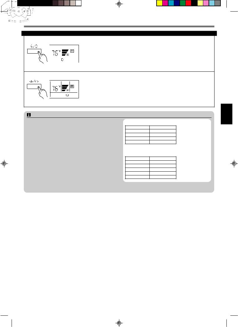
OPERATION
Room temperature sensor selection
THERMO
SENSOR
Indoor unit
Press the THERMO SENSOR button to select whether the room temperature is detected at the indoor unit (remote sensor) or the remote controller.
When the thermo sensor display appears, the room temperature is detected at the remote controller.
NOTES
•This function is locked at the factory. In order to detect the room temperature correctly, consult authorized service personnel when using this function.
•If this function is locked, the location where the room temperature is detected cannot be changed and the mark flashes when the THERMO SENSOR button is pushed.
Part lock function
|
DAY |
CLOCK ADJUST |
DAY OFF |
SET BACK |
|
 DELETE
  SET
SET
Press the DAY (DAY OFF) button and SET button simultaneously for 2 seconds or more to activate the part lock function and lock all of the buttons on the remote controller except the Start/Stop button, Set Temperature buttons, Master Control button, and Fan Control button. Press the buttons again for 2 seconds or more to deactivate the part lock function.
When the part lock function is activated, the  mark appears. If any button is pressed during the part lock, the
PL display flashes.
ON/OFF TIMER
Instructions related to heating are applicable to “HEAT PUMP MODELS” and “HEAT RECOVERY MODELS” only.
The timer function is not available depending on the model.
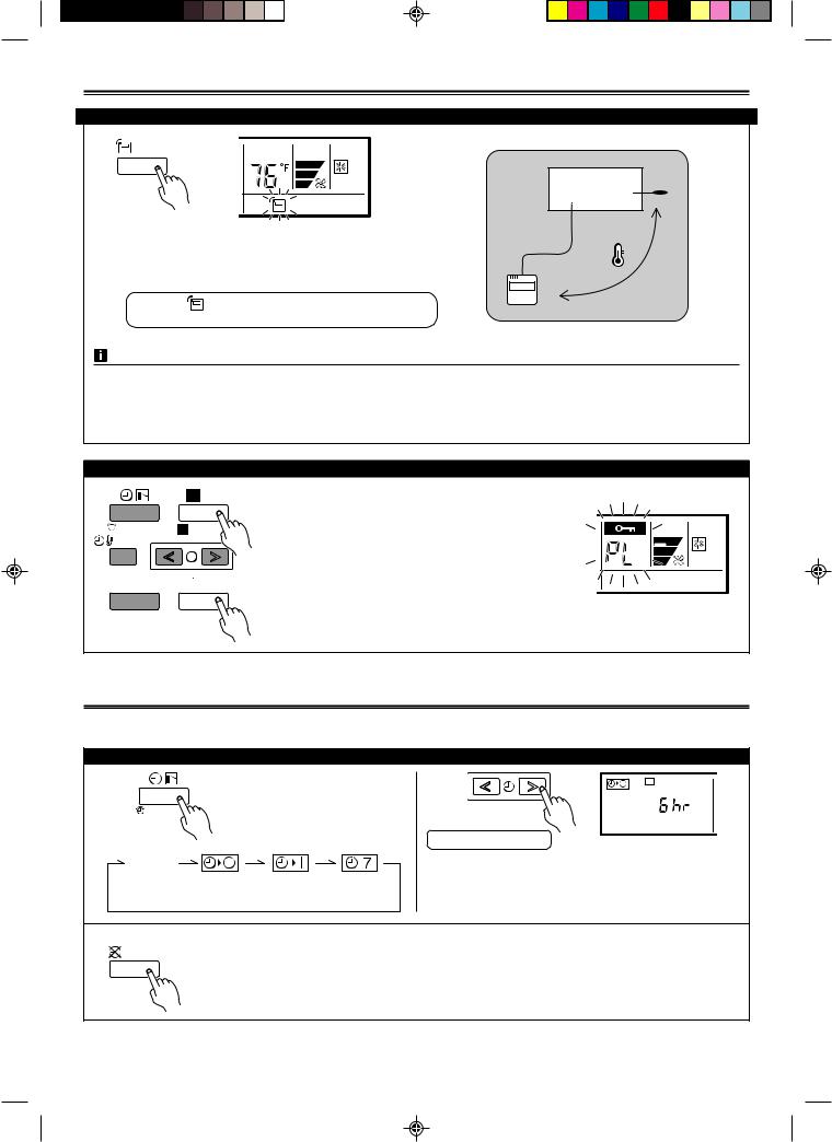
To set the ON/OFF timer
1 |
|
Press the TIMER MODE button to |
|
select the ON TIMER or OFF |
|
CLOCK ADJUST |
TIMER. |
No display |
|
|
|
NON |
OFF |
ON |
WEEKLY |
STOP |
TIMER |
TIMER |
TIMER |
2 |
SU MO TU WE TH FR SA |
|
From 1 to 24 hours
ex. OFF timer set for 6 hours Press the SET TIME buttons to set the time.
After the time is set, the timer will start automatically. The amount of time until the OFF timer operates that is displayed on the timer display decreases as time passes.
● To cancel the timer mode
DELETE |
• Press the DELETE button to cancel the timer mode. |
|
|
|
• The timer mode can also be canceled by changing the timer mode using the TIMER MODE button. |
En-5

WEEKLY TIMER
Instructions related to heating are applicable to “HEAT PUMP MODELS” and “HEAT RECOVERY MODELS” only.
The timer function is not available depending on the model.
To set the WEEKLY timer
1 |
SU MO TU WE TH FR SA |
2 |
SET |
|||
CLOCK ADJUST |
|
|
|
|
||
|
3 |
6 |
9 |
12 15 18 21 |
|
|
Press the TIMER MODE button to select the weekly timer. |
Press the SET button for 2 seconds or |
|||||
|
|
|
|
|
more. |
|
3 |
● Day of the week setting |
SU |
MO |
TU |
WE |
|
TH |
FR |
SA |
||
DAY |
ALL |
|
|||||||||
|
SET |
|
|
|
|
|
|
|
|
|
|
|
DAY OFF |
2 |
|
|
|
SU MO TU WE TH FR SA |
|
|
|||
|
1 |
|
|
|
|
|
|||||
|
|
|
|
|
|
|
|
|
|
||
Press the DAY button to select the day of the week, and then press the SET |
3 |
6 |
9 |
12 15 18 21 |
|
|
|||||
button to confirm the setting. |
|
|
|
|
|
||||||
|
|
|
|
|
|
|
|
|
|||
*For ALL, all of the days can be set together when a  appears around each day.
4 |
● Time setting |
|
|
|
|
|
SET |
|
|
|
|
|
|
|
|
|
1 |
2 |
|
|
ON-1 |
OFF-1 |
ON-2 |
OFF-2 |
When the operating time is set, the  mark appears.
SU MO TU WE TH FR SA
3 6 9 12 15 18 21 
ex. The timer is set for 7:00 A.M.–6:00 P.M. (7:00–18:00)
Press the SET TIME buttons to set the ON time in 30-minute increments, then press the SET button to proceed to the OFF time setting. Set the OFF time in the same way.
If necessary, set the second weekly timer settings in the same way.
5
Repeat steps 3 and 4 to set the weekly timer for another day of the week.
6  SET
SET
Press the SET button for 2 seconds or more to complete the weekly timer settings.
●To delete the operating time
 DELETE
If the DELETE button is pressed during steps 3 or 4, the operating time for the selected day will be deleted.
If all the days are selected, the operating times for all of the days will be deleted.
En-6
WEEKLY TIMER
To start/cancal the WEEKLY timer operation
● To start
SU MO TU WE TH FR SA
CLOCK ADJUST |
3 6 9 12 15 18 21 |
|
|
|
|
|
|
|
|
|
|
|
|
|
When the weekly timer is selected, the |
3 6 9 12 15 18 21 |
|||||||||||
timer starts automatically. |
ex. Operating time 7:00 A.M. |
|||||||||||
|
–6:00 P.M. (7:00–18:00) |
|||||||||||
|
The operating time for the current |
|||||||||||
|
day is displayed. |
|||||||||||
● To cancel
 DELETE
•Press the DELETE button to cancel the timer mode.
•The timer mode can also be canceled by changing the timer mode using the TIMER MODE button.
NOTES
(1)PRECAUTIONS DURING WEEKLY TIMER SETUP Setup is not possible in the following cases, so amend the time.
•Be sure to set the ON time first, then the OFF time. If either the ON time or the OFF time is not set correctly, the timer will not operate properly.
•The WEEKLY 2 settings cannot be set earlier than the WEEKLY 1 settings.
•The WEEKLY 1 and WEEKLY 2 time spans cannot overlap.
(2)The earliest OFF time you can set is 30 minutes after the ON time.
(3)The OFF time can be carried over to the next day.
(4)Even if the timer operation is set, the timer indicator lamp of the indoor unit does not light up. (The timer indicator lamp is used for wireless remote controllers only.)
To set the DAY OFF (for a holiday)
1 |
SET |
2 |
DAY |
3 |
DAY |
|
DAY OFF |
DAY OFF |
|||
During the weekly timer, |
Select the day to set the DAY |
Press the DAY (DAY OFF) |
|||
press the SET button for 2 |
OFF. |
|
button for 2 seconds or |
||
seconds or more to set the |
|
|
more to set the DAY OFF. |
||
day. |
|
|
|
|
|
4  SET
SET
Press the SET button for 2 seconds or more to complete the DAY OFF setting.
SU MO TU WE TH FR SA |
SU MO TU WE TH FR SA |
 mark: Indicates the DAY OFF
|
|
|
|
|
|
|
|
|
|
|
|
|
● To cancel |
|
|
|
|
|
|
|
|
|
|
|
|
|
|
3 6 9 12 15 18 21 |
3 6 9 12 15 18 21 |
Follow the same procedures as |
|||||||||||
|
ex. The DAY OFF is set for Monday. |
those for setup. |
|||||||||||
|
|
||||||||||||
NOTES
(1)The DAY OFF setting is only available for days for which weekly settings already exist.
(2)If the operating time carries over to the next day (during a next day setting), the effective DAY OFF range will be set as shown below.
● Normal |
|
|
|
|
DAY OFF |
|
|
|
● Next day setting |
|
|
|
DAY OFF |
|
|
|
|
||||||||||||
|
|
|
|
|
|
|
|
|
|
|
|
|
|
|
|
|
|
|
|
|
|
||||||||
|
|
|
|
|
|
|
|
|
|
|
|
|
|
|
|
|
|
|
|
|
|
|
|
|
|||||
|
ON |
OFF |
|
ON |
OFF |
|
|
|
|
ON |
OFF |
ON |
OFF |
||||||||||||||||
|
|
WEEKLY |
|
|
|
|
WEEKLY |
|
|
|
|
|
|
|
WEEKLY |
|
|
|
|
WEEKLY |
|
|
|
|
|||||
|
|
|
|
|
|
|
|
|
|
|
|
|
|
|
|
|
|
|
|
|
|
|
|
|
|
|
|
|
|
|
|
Preceding day |
|
|
Setting day |
|
Next day |
|
Preceding day |
|
|
|
|
|
Setting day |
|
|
Next day |
|||||||||||
|
|
|
|
|
|
|
|
|
|
|
|||||||||||||||||||
(3)The DAY OFF setting can only be set one time. The DAY OFF setting is cancelled automatically after the set day has passed.
En-7
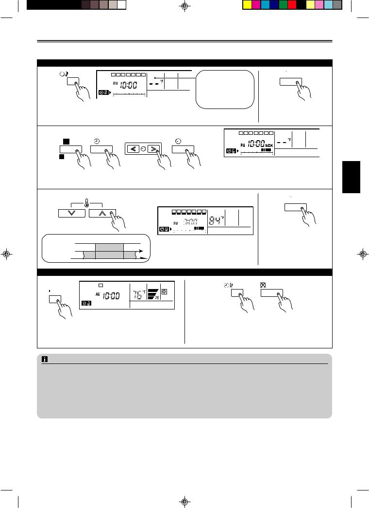
TEMPERATURE SET BACK TIMER
Instructions related to heating are applicable to “HEAT PUMP MODELS” and “HEAT RECOVERY MODELS” only.
The timer function is not available depending on the model.
To set the temperature SET BACK timer
1 |
SET BACK |
SU MO TU |
WE TH FR SA |
If there is no existing |
|
|
|
||
|
|
|
|
|
|
|
|
|
SET BACK tempera- |
|
|
|
|
ture setting, “- -” will |
|
|
3 6 9 |
12 15 18 21 |
be displayed for the |
|
|
|
|
temperature. |
Press the SET BACK button to change to the SET BACK confirmation display. The SET BACK operating time and the set temperature will be displayed.
2  SET
SET
Press the SET button for 2 seconds or more.
3 |
● Day setting |
|
● Operating time setting |
|
SU MO TU |
WE TH FR SA |
||
DAY |
SET |
SET |
|
|
|
|
|
|
|
|
|
|
|
|
|||
|
DAY OFF |
|
|
|
3 |
6 |
9 |
12 15 18 21 |
|
2 |
|
4 |
|
|
|
|
|
|
1 |
3 |
ex. When setting all days together |
|||||
Follow steps 3 and 4 in “To set the WEEKLY timer” (p. 6). The DELETE button is also used as described in the procedures for the weekly timer.
4 |
● Temperature setting |
Press the SET TEMPERATURE buttons to |
|
set the temperature (from 48 °F to 88 °F). |
|
|
SU MO TU WE TH FR SA |
|
|
|
|
3 |
6 |
9 |
12 15 18 21 |
SET BACK |
ON |
84°F |
OFF |
ex. Operating time 3:00–10:00 P.M. |
|||
temperature |
76°F |
|
|
(15:00–22:00) |
|||
Normal |
|
|
76°F |
|
|
|
|
temperature |
|
|
|
|
|
|
|
5  SET
SET
Repeat steps 3 and 4. Press the SET button for 2 seconds or more to complete the temperature SET BACK timer settings.
To start/cancel the temperature SET BACK timer operation
● To start
SU MO TU WE TH FR SA
 SET BACK
ex. Display during SET BACK timer operation (The operating time will not be displayed.)
Press the SET BACK button. The SET BACK confirmation display appears for 5 seconds, and then the timer starts automatically.
● To cancel |
SET BACK |
DELETE |
|
||
|
1 |
2 |
Press the SET BACK button, and then press the DELETE button while the SET BACK confirmation display is displayed. Even if the SET BACK button is pressed again, the SET BACK timer will be cancelled.
NOTES
(1)The SET BACK timer only changes the set temperature, it cannot be used to start or stop air conditioner operation.
(2)The SET BACK timer can be set to operate up to two times per day but only one temperature setting can be used.
(3)The SET BACK timer can be used together with the ON, OFF, and weekly timer functions.
(4)During the COOL/DRY mode, the air conditioner will operate at a minimum of 64 °F even if the SET BACK temperature is set to 62 °F or lower.
(5)The SET BACK operating time is displayed only in the SET BACK confirmation display. (Refer to step 1 for the SET BACK confirmation display.)
(6)Room temperatures as low as 48, 52, and 56 °F cannot be set depending on the model.
En-8
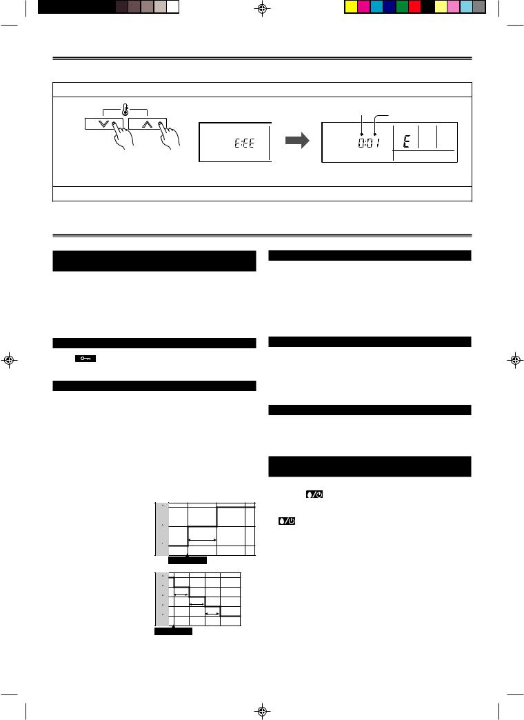
SELF-DIAGNOSIS
When the error indication “E:EE” is displayed, inspection of the air conditioning system is necessary. Please consult authorized service personnel.
(1) Stop the air conditioner operation.
(2) |
Faulty unit number |
|
(remote controller address) |
|
|
|
Error code |
|
|
|
|
SU MO TU WE TH FR SA |
SU MO TU WE TH FR SA |
|
ex. Error display |
ex. Self-diagnosis check |
|
Press the SET TEMPERATURE buttons
 simultaneously for 5 seconds or more to start the self-diagnosis.
(3) Press the SET TEMPERATURE buttons simultaneously for 5 seconds or more to stop the self-diagnosis.
OPERATING TIPS
Instructions related to heating are applicable to “HEAT PUMP MODELS” and “HEAT RECOVERY MODELS” only.
Cooling/heating priority (AIRSTAGETM
(VRF system Heat Pump model only))
•If another indoor unit in the same system is already operating in the cooling mode or dry mode, heating mode settings cannot be performed.
•If another indoor unit in the same system is already operating in the heating mode, cooling mode or dry mode settings cannot be performed.
Weekly timer
•Set different operating times for each day of the week.
•Set one or two operating spans (one or two ON times and one or two OFF times) per day.
•Set time to a resolution of 30 minutes.
•OFF time can be carried over to the subsequent day.
•Use the “DAY OFF” setting to cancel operation for any day of the coming week (one-time cancellation).
Setting restriction
When is displayed there are functions for which settings cannot be made.
Energy save
•The energy conservation mode (ENERGY SAVE) raises the set temperature slightly in the cooling mode and lowers the set temperature in the heating mode to economically control the operation of the unit.
•If you press the ENERGY SAVE button while the unit is in the timer mode, the unit will go into the conservation mode when the unit starts with the timer.
•If you turn off the air conditioner while in the conservation mode, the mode will be shut off.
•The temperature set on the remote controller will not change if the energy save mode is used.
During cooling operation
When the ENERGY SAVE is pressed, the thermostat setting is automatically raised 2 °F every 60 minutes, until the thermostat is raised a total of 4 °F.
During heating operation
When the ENERGY SAVE is pressed, the thermostat setting is automatically lowered 2 °F every 30 minutes, until the thermostat is lowered a total of 8 °F.
82 F
80 F
60 min.
78 F
Energy save
74 F |
72 F |
70 F |
30 min. |
68 F |
30 min. |
66 F |
30 min. |
Energy save
Day off
•Use the “DAY OFF” setting to switch off timed operation for a selected day in the coming week.
•This is a temporary, one-time setting. The “DAY OFF” setting is automatically cleared as soon as the specified day passes.
Temperature SET BACK timer
Use this timer function to change the set temperature in the operation times set for each day of the week.
This can be used together with other timer settings.
Automatic defrosting operation and oil
recovery operation
• During automatic defrosting operation and oil recovery operation,  will be displayed on the remote controller.
•Display when indoor and outdoor unit operation modes are different (for multi split type only)
 will also be displayed on the remote controller if the operation modes of the indoor unit and outdoor unit are different when the indoor unit starts operating.
En-9
 Loading...