


 Loading...
Options Guide - English
PRIMERGY TX300 S6 Server
Options Guide
Edition August 2010
Comments… Suggestions… Corrections…
The User Documentation Department would like to know your opinion of this manual. Your feedback helps us optimize our documentation to suit your individual needs.
Feel free to send us your comments by e-mail to email: manuals@ts.fujitsu.com.
Certified documentation according to DIN EN ISO 9001:2000
To ensure a consistently high quality standard and user-friendliness, this documentation was created to meet the regulations of a quality management system which complies with the requirements of the standard DIN EN ISO 9001:2000.
cognitas. Gesellschaft für Technik-Dokumentation mbH www.cognitas.de
Copyright and Trademarks
Copyright © 2010 Fujitsu Technology Solutions GmbH.
All rights reserved.
Delivery subject to availability; right of technical modifications reserved.
All hardware and software names used are trademarks of their respective manufacturers.
–The contents of this manual may be revised without prior notice.
–Fujitsu assumes no liability for damages to third party copyrights or other rights arising from the use of any information in this manual.
–No part of this manual may be reproduced in any form without the prior written permission of Fujitsu.
Microsoft, Windows, Windows Server, and Hyper V are trademarks or registered trademarks of Microsoft Corporation in the USA and other countries.
Intel and Xeon are trademarks or registered trademarks of Intel Corporation or its subsidiaries in the USA and other countries.

Before reading this manual
For your safety
This manual contains important information for safely and correctly using this product.
Carefully read the manual before using this product. Pay particular attention to the accompanying manual "Safety Notes and Regulations" and ensure these safety notes are understood before using the product. Keep this manual and the manual "Safety Notes and Regulations" in a safe place for easy reference while using this product.
Radio interference
This product is a "Class A" ITE (Information Technology Equipment). In a domestic environment this product may cause radio interference, in which case the user may be required to take appropriate measures. VCCI-A
Aluminum electrolytic capacitors
The aluminum electrolytic capacitors used in the product's printed circuit board assemblies and in the mouse and keyboard are limited-life components. Use of these components beyond their operating life may result in electrolyte leakage or depletion, potentially causing emission of foul odor or smoke.
As a guideline, in a normal office environment (25°C) operating life is not expected to be reached within the maintenance support period (5 years). However, operating life may be reached more quickly if, for example, the product is used in a hot environment. The customer shall bear the cost of replacing replaceable components which have exceeded their operating life. Note that these are only guidelines, and do not constitute a guarantee of trouble-free operation during the maintenance support period.
High safety use
This product has been designed and manufactured for general uses such as general office use, personal use, domestic use and normal industrial use. It has not been designed or manufactured for uses which demand an extremely high level of safety and carry a direct and serious risk to life or body if such safety cannot be ensured.
TX300 S6 |
Options Guide |

These uses include control of nuclear reactions in nuclear power plants, automatic airplane flight control, air traffic control, traffic control in mass transport systems, medical devices for life support, and missile guidance control in weapons systems (hereafter, "high safety use"). Customers should not use this product for high safety use unless measures are in place for ensuring the level of safety demanded of such use. Please consult the sales staff of Fujitsu if intending to use this product for high safety use.
Measures against momentary voltage drop
This product may be affected by a momentary voltage drop in the power supply caused by lightning. To prevent a momentary voltage drop, use of an AC uninterruptible power supply is recommended.
(This notice follows the guidelines of Voltage Dip Immunity of Personal Computer issued by JEITA, the Japan Electronics and Information Technology Industries Association.)
Technology controlled by the Foreign Exchange and Foreign Trade Control Law of Japan
Documents produced by Fujitsu may contain technology controlled by the Foreign Exchange and Foreign Trade Control Law of Japan. Documents which contain such technology should not be exported from Japan or transferred to non-residents of Japan without first obtaining authorization in accordance with the above law.
Harmonic Current Standards
This product conforms to harmonic current standard JIS C 61000-3-2.
Only for the Japanese market:
About SATA hard disk drives
The SATA version of this server supports hard disk drives with SATA / BC-SATA storage interfaces. Please note that the usage and operation conditions differ depending on the type of hard disk drive used.
Please refer to the following internet address for further information on the usage and operation conditions of each available type of hard disk drive:
http://primeserver.fujitsu.com/primergy/harddisk/
Options Guide |
TX300 S6 |

Only for the Japanese market:
I Although described in this manual, some sections do not apply to the Japanese market. These options and routines include:
–USB Flash Module (UFM)
–CSS (Customer Self Service)
TX300 S6 |
Options Guide |

Options Guide |
TX300 S6 |

Contents
1 |
Preface . . . . . . . . . . . . . . . . . . . . . . . . . . . . . |
11 |
1.1 |
Concept and target groups . . . . . . . . . . . . . . . . . . |
12 |
1.2 |
Documentation overview . . . . . . . . . . . . . . . . . . . |
12 |
1.3 |
Expansions and conversions . . . . . . . . . . . . . . . . . |
14 |
1.4 |
Notational conventions . . . . . . . . . . . . . . . . . . . . |
16 |
2Procedure . . . . . . . . . . . . . . . . . . . . . . . . . . . . 17
3Safety instructions . . . . . . . . . . . . . . . . . . . . . . . 19
4Preparation . . . . . . . . . . . . . . . . . . . . . . . . . . . 27
4.1Floorstand model . . . . . . . . . . . . . . . . . . . . . . . . 28
4.1.1 |
Opening the server . . . . . . . . . . . . . . . . . . . . . . . |
28 |
4.1.2 |
Removing the front cover . . . . . . . . . . . . . . . . . . . . |
29 |
4.1.3 |
Removing the server feet . . . . . . . . . . . . . . . . . . . . |
31 |
4.2Rack model . . . . . . . . . . . . . . . . . . . . . . . . . . . 32
4.2.1 |
Opening the server . . . . . . . . . . . . . . . . . . . . . . . 32 |
4.2.2Removing the rack front cover . . . . . . . . . . . . . . . . . . 34
4.3Removing the fan carrier . . . . . . . . . . . . . . . . . . . . 35
5 |
Main memory . . . . . . . . . . . . . . . . . . . . . . . . . . 37 |
5.1Memory modules . . . . . . . . . . . . . . . . . . . . . . . . 38
5.2 |
Expanding the main memory . . . . . . . . . . . . . . . . . 40 |
TX300 S6 |
Options Guide |

Contents
6 |
Processors . . . . . . . . . . . . . . . . . . . . . . . . . . . . 41 |
|
6.1 |
Installing a second processor |
. . . . . . . . . . . . . . . . . 42 |
6.2 |
Replacing the processor . . |
. . . . . . . . . . . . . . . . . . 47 |
6.3Replacing the heat sink . . . . . . . . . . . . . . . . . . . . . 52
7 |
Accessible drives and LSD/LSP . . . . . . . . . . . . . . . . 53 |
7.1Equipping of the bays . . . . . . . . . . . . . . . . . . . . . . 54
7.2 |
Accessible 5.25-inch drive |
. . |
. . . . . . |
. . . . . . . |
. |
. . |
. 56 |
7.2.1 |
Removing the dummy cover |
. . |
. . . . . . |
. . . . . . . |
. |
. . |
. 56 |
7.2.2Installing an accessible 5.25-inch drive . . . . . . . . . . . . . . 58
7.3Multibay 1 . . . . . . . . . . . . . . . . . . . . . . . . . . . . 59
7.3.1Equipping Multibay 1 . . . . . . . . . . . . . . . . . . . . . . . 59
7.3.1.1Installing LSP or LSD . . . . . . . . . . . . . . . . . . . . . 59
7.3.1.2Installing a slimline DVD drive . . . . . . . . . . . . . . . . . 61
7.3.2Installing Multibay 1 . . . . . . . . . . . . . . . . . . . . . . . . 64
7.4 |
HDD extension box . . . . . . . . . . . . . . . . . . . . . . . 68 |
7.4.1Multibay 2 . . . . . . . . . . . . . . . . . . . . . . . . . . . . . 69
7.4.1.1Installing Multibay 2 . . . . . . . . . . . . . . . . . . . . . . 70
7.4.2 |
2.5-inch HDD extension box . . . . . . . . . . . . . . . . . . . 72 |
7.4.2.1Installing 2.5 inch HDD extension box . . . . . . . . . . . . . 73
8 |
Expansion cards and BBU |
. . . . . . . . . . . . . . . . . . . 75 |
8.1 |
Installing expansion cards |
. . . . . . . . . . . . . . . . . . . 76 |
8.2 |
Installing a BBU . . . . . . |
. . . . . . . . . . . . . . . . . . . 79 |
9 |
Further options . . . . . . |
. . . . . . . . . . . . . . . . . . . 93 |
9.1TPM . . . . . . . . . . . . . . . . . . . . . . . . . . . . . . . . 93
9.2USB Flash Module (UFM) . . . . . . . . . . . . . . . . . . . . 96
10 Conversion from a floorstand model to a rack model . . . . . 99
Options Guide |
TX300 S6 |

|
Contents |
11 |
Completion . . . . . . . . . . . . . . . . . . . . . . . . . . . 105 |
11.1 |
Installing the fan carrier . . . . . . . . . . . . . . . . . . . . 105 |
11.2Floorstand model . . . . . . . . . . . . . . . . . . . . . . . . 107
11.2.1Mounting the server feet . . . . . . . . . . . . . . . . . . . . . 107
11.2.2Attaching the front cover . . . . . . . . . . . . . . . . . . . . . 108
11.2.3Closing the server . . . . . . . . . . . . . . . . . . . . . . . . 110
11.3Rack model . . . . . . . . . . . . . . . . . . . . . . . . . . . 111
11.3.1 |
Attaching the rack front cover . . . . . . . . . . . . . . . . . . 111 |
11.3.2Closing the server . . . . . . . . . . . . . . . . . . . . . . . . 112
12 |
Appendix |
. . . . . . . . . . . . . . . . . . . . . . . . . . . |
. 115 |
|||||||
12.1 |
Cabling . |
. |
. . . . . . . . . . . . . . . . . |
. |
. . |
. . |
. . |
. |
. |
. 115 |
Index |
. . . . . . . . . |
. . . . . . . . . . . . . . . . . |
. |
. . |
. . |
. . |
. |
. |
. 121 |
|
TX300 S6 |
Options Guide |

Contents
Options Guide |
TX300 S6 |
1 Preface
With top dual processor performance, the PRIMERGY TX300 S6 tower server is an all-purpose server for medium sized companies and branches of large enterprises. The system is ideal for use as a versatile business server for business critical applications and dedicated tasks. Thanks to internal SAS/SATA hard disk capacity of up to 6 or 8 TB, the PRIMERGY TX300 S6 is also suitable for use as a platform for highly data intensive solutions. Furthermore, it is the ideal solution for smaller mySAP installations and directory or cache services in medium sized and large companies.
The PRIMERGY TX300 S6 offers a balanced architecture that incorporates next generation main memory (DDR3) and I/O technologies (PCIe Gen2). The HDD backplane is already provided for SAS 2.0 and 6 Gbit/s SAS and the chipset prepared for the next generation of 6-core processors. High performance, scalability, impressive reliability and excellent extension options are combined in a powerful design.
The Cool-safe™ cooling concept with improved air flow cooling technology (honeycomb design) ensures the highest possible performance of the processors at work; at the same time, the system is extremely reliable thanks to the reduced heat dissipation.
The new PRIMERGY TX300 S6 can also be converted quickly and easily into a space-saving rack system that only takes up 4 height units (HU).
TX300 S6 |
Options Guide |
11 |

Concept and target groups |
Preface |
1.1Concept and target groups
This Options Guide shows you how to extend and upgrade your server.
VCAUTION!
The activities described in this manual may only be performed by technical specialists.
IThe installation and removal of the hot-plug components is described in the Operating Manual supplied with the server.
1.2Documentation overview
More information on your PRIMERGY TX300 S6 can be found in the following documents:
– "Quick Start Hardware - PRIMERGY TX300 S6" leaflet
"-PRIMERGY TX300 S6" for theJapanese market (only included as a printed copy)
–"Quick Start Software - Quick Installation Guide" DVD booklet
(only included with the PRIMERGY ServerView Suite as a printed copy) except for the Japanese market
–"Safety notes and other important information" manual
"" for the Japanese market
–"Warranty" manual
"" for the Japanese market
–"PRIMERGY ServerView Suite Local Service Concept - LSC" manual
–"Returning used devices" manual and "Service Desk" leaflet
"" for the Japanese market
–"PRIMERGY TX300 S6 Server Operating Manual"
–"PRIMERGY TX300 S6 Server Options Guide"
–"System Board D2619-N for PRIMERGY RX/TX300 S6 Technical Manual"
–"D2619-N BIOS Setup Utility for PRIMERGY RX300 S6 and TX300 S6" manual
12 |
Options Guide |
TX300 S6 |

Preface Documentation overview
IPRIMERGY manuals are available in PDF format on the ServerView Suite DVD 2. The ServerView Suite DVD 2 is part of the ServerView Suite supplied with every server.
If you no longer have the ServerView Suite DVDs, you can obtain the relevant current versions using the order number U15000-C289 (the order number for the Japanese market: please refer to the configurator of the server http://primeserver.fujitsu.com/primergy/system.html).
The PDF files of the manuals can also be downloaded free of charge from the Internet. The overview page showing the online documentation available on the Internet can be found using the URL (for EMEA market): http://manuals.ts.fujitsu.com. The PRIMERGY server documentation can be accessed using the Industry standard servers navigation option.
For the Japanese market please use the URL:
http://primeserver.fujitsu.com/primergy/manual.html.
Further sources of information:
–PRIMERGY Abbreviations and Glossary on the ServerView Suite DVD 2
–Manual for the monitor
–Documentation for the boards and drives
–Operating system documentation
–Information files in your operating system
TX300 S6 |
Options Guide |
13 |

Expansions and conversions |
Preface |
1.3Expansions and conversions
Main memory
The system board offers 18 slots for memory modules. 9 memory slots can be used in mono processor configurations.
ECC with memory scrubbing and the Single Device Data Correction (SDDC) function is standard.
There are three modes of operation for the main memory:
–Independent Channel Mode / Performance Mode (recommended)
–Mirrored Channel Mode
–Spare Channel Mode
Depending on the mode of operation there are different population requirements.
Second processor
The system board can be upgraded with a second processor. Only processors of the same type may be used on the system board. That means the number of the internal processor cores as well as the primary clock and the FSB frequency have to be the same. For dual operation, use a suitable multiprocessor operating system.
Accessible drives
Three 5.25-inch bays are available for accessible drives.
You can use these bays as follows:
–You can install DVD drives or magnetic tape drives.
–You can install a Multibay 1 in the bottom bay. The Multibay 1 offers bays for a slimline DVD drive and a ServerView Local Service Panel (LSP) or a ServerView Local Service Display (LSD).
–In the two lower bays, you can install a Multibay 2. The Multibay 2 offers bays for two additional 3.5-inch hard disk drives, a slimline DVD drive and a ServerView Local Service Panel (LSP) or a ServerView Local Service Display (LSD).
–You can install a Multibay 1 in the bottom bay (see above) and an HDD extension box for 2.5-inch SAS hard disk drives in the two upper bays.
14 |
Options Guide |
TX300 S6 |

Preface |
Expansions and conversions |
LSD/LSP
The system board supports the CSS (Customer Self Service) functionality (description see the Operating Manual). You can install a ServerView Local Service Display (LSD) or ServerView Local Service Panel (LSP) for an easier identification of the defective components.
Additional expansion cards in the PCI Express slots
The system board offers seven PCI Express slots. Slots 1-5 are connected as x4 interfaces, whereby slot 3 and slot 5 are used as x8 interfaces if slot 2 and slot 4 are empty.
I Slot 1 is the preferred slot for the SAS/SATA RAID controller (bootable).
Slot 5 and slot 7 allow the mechanical installation of x16 PCIe expansion cards. The bus width is restricted to 8 lanes.
Battery Backup Unit
A Battery Backup Unit (BBU) backs up the memory contents of the SAS/SATA RAID controller in the event of a power failure. One BBU can be installed for each SAS/SATA RAID controller. A maximum of three BBUs can be installed for each system.
Trusted Platform Module (TPM)
A Trusted Platform Module (TPM) for safer storage of keys can be implemented as an option. This module enables programs from third party manufacturers to store key information (e.g. drive encryption using Windows Bitlocker Drive Encryption).
The TPM is activated via the BIOS system (for more information, refer to the "D2619-N BIOS Setup Utility for PRIMERGY RX300 S6 and TX300 S6" manual).
VCAUTION!
–When using the TPM, note the program descriptions provided by the third party manufacturers.
–You must also create a backup of the TPM content. To do this, follow the third party manufacturer's instructions. Without this backup, if the TPM or the system board is faulty you will not be able to access your data.
TX300 S6 |
Options Guide |
15 |

Notational conventions |
Preface |
–If a failure occurs, please inform your service about the TPM activation before it takes any action, and be prepared to provide them with your backup copies of the TPM content.
USB Flash Module (UFM)
The server can be equipped with a USB Flash Module (UFM).
This module can be used as optional memory for software (e.g. VMware) or as a software dongle.
Conversion from a floorstand model to a rack model
The floorstand model can be converted into a space-saving rack system that only takes up 4 height units (HU). The server can thus be installed in any typical rack systems.
1.4Notational conventions
The following notational conventions are used in this manual:
Text in italics |
indicates commands or menu items. |
|
|
"Quotation marks" |
indicate names of chapters and terms that are being |
|
emphasized. |
|
|
Ê |
describes activities that must be performed in the order |
|
shown. |
|
|
VCAUTION! |
pay particular attention to texts marked with this symbol. |
Failure to observe this warning may endanger your life, |
|
|
destroy the system or lead to the loss of data. |
|
|
I |
indicates additional information, notes and tips. |
|
|
16 |
Options Guide |
TX300 S6 |

2 Procedure
VCAUTION!
●The actions described in this manual shall be performed by technical specialists. A technical specialist is a person who is trained to install the server including hardware and software.
●Repairs to the device that do not relate to CSS failures shall be performed by service personnel. Please note that unauthorized interference with the system will void the warranty and exempt the manufacturer from all liability.
●Any failure to observe the guidelines in this manual, and any improper repairs could expose the user to risks (electric shock, energy hazards, fire hazards) or damage the equipment.
ÊFirst of all, carefully read the safety instructions in the chapter "Safety instructions" on page 19.
ÊMake sure that all necessary manuals (see the section "Documentation overview" on page 12) are available; print the PDF files if required. Most importantly, you will need the Operating Manual for the server and the Technical Manual for the system board.
ÊShut the server down correctly, switch it off, disconnect the power cords and open the server as described in the chapter chapter "Preparation" on page 27.
ÊCarry out the expansion or upgrade of your server as described in the pertinent chapter.
IInstallation and removal of the hot-plug components are described in
the Operating Manual.
ÊClose the server, connect it to the power outlet, and switch it on as described in the chapter chapter "Completion" on page 105.
ÊStart the operating system and make the appropriate configuration if necessary (see the Operating Manual).
I For the latest information on optional products provided for the TX300 S6 see the configurator of this server: https://sp.ts.fujitsu.com/dmsp/docs/cnfgtx300s6.pdf
TX300 S6 |
Options Guide |
17 |

Procedure
18 |
Options Guide |
TX300 S6 |

3 Safety instructions
IThe following safety instructions are also provided in the manual "Safety Notes and Regulations".
This device meets the relevant safety regulations for IT equipment. If you have any questions about whether you can install the server in the intended environment, please contact your sales outlet or our customer service team.
VCAUTION!
●The actions described in this manual shall be performed by technical specialists. A technical specialist is a person who is trained to install the server including hardware and software.
●Repairs to the device that do not relate to CSS failures shall be performed by service personnel. Please note that unauthorized interference with the system will void the warranty and exempt the manufacturer from all liability.
●Any failure to observe the guidelines in this manual, and any improper repairs could expose the user to risks (electric shock, energy hazards, fire hazards) or damage the equipment.
●Before installing/removing internal options to/from the server, turn off the server, all peripheral devices, and any other connected devices. Also unplug all power cords from the power outlet. Failure to do so can cause electric shock.
TX300 S6 |
Options Guide |
19 |

Safety instructions
Before starting up
V CAUTION!
●During installation and before operating the device, observe the instructions on environmental conditions for your device.
●If the device is brought in from a cold environment, condensation may form both inside and on the outside of the device.
Wait until the device has acclimatized to room temperature and is absolutely dry before starting it up. Material damage may be caused to the device if this requirement is not observed.
●Transport the device only in the original packaging or in packaging that protects it from knocks and jolts.
Installation and operation
VCAUTION!
●This unit should not be operated in ambient temperatures above 35 °C.
●If the unit is integrated into an installation that draws power from an industrial power supply network with an IEC309 connector, the power supply's fuse protection must comply with the requirements for nonindustrial power supply networks for type A connectors.
●The unit automatically adjusts itself to a mains voltage in a range of 100 V - 240 V. Ensure that the local mains voltage lies within these limits.
●This device must only be connected to properly grounded power outlets or insulated sockets of the rack's internal power supply with tested and approved power cords.
●Ensure that the device is connected to a properly grounded power outlet close to the device.
20 |
Options Guide |
TX300 S6 |
Safety instructions
VCAUTION!
●Ensure that the power sockets on the device and the properly grounded power outlets are freely accessible.
●The On/Off button or the main power switch (if present) does not isolate the device from the mains power supply. To disconnect it completely from the mains power supply, unplug all network power plugs from the properly grounded power outlets.
●Always connect the server and the attached peripherals to the same power circuit. Otherwise you run the risk of losing data if, for example, the server is still running but a peripheral device (e.g. memory subsystem) fails during a power outage.
●Data cables must be adequately shielded.
●Ethernet cabling has to comply with EN 50173 and EN 50174-1/2 standards or ISO/IEC 11801 standard respectively. The minimum requirement is a Category 5 shielded cable for 10/100 Ethernet, or a Category 5e cable for Gigabit Ethernet.
●Route the cables in such a way that they do not create a potential hazard (make sure no-one can trip over them) and that they cannot be damaged. When connecting the server, refer to the relevant instructions in this manual.
●Never connect or disconnect data transmission lines during a storm (risk of lightning hazard).
●Make sure that no objects (e.g. jewelry, paperclips etc.) or liquids can get inside the server (risk of electric shock, short circuit).
●In emergencies (e.g. damaged casing, controls or cables, penetration of liquids or foreign bodies), switch off the server immediately, remove all power plugs and contact your sales outlet or customer service team.
TX300 S6 |
Options Guide |
21 |

Safety instructions
VCAUTION!
●Proper operation of the system (in accordance with IEC 60950-1/2 resp. EN 60950-1/2) is only ensured if the casing is completely assembled and the rear covers for the installation slots have been fitted (electric shock, cooling, fire protection, interference suppression).
●Only install system expansions that satisfy the requirements and rules governing safety and electromagnetic compatibility and those relating to telecommunication terminals. If you install other expansions, they may damage the system or violate the safety regulations. Information on which system expansions are approved for installation can be obtained from our customer service center or your sales outlet.
●The components marked with a warning notice (e.g. lightning symbol) may only be opened, removed or exchanged by authorized, qualified personnel. Exception: CSS components can be replaced.
●The warranty is void if the server is damaged during installation or replacement of system expansions.
●Only set screen resolutions and refresh rates that are specified in the operating manual for the monitor. Otherwise, you may damage your monitor. If you are in any doubt, contact your sales outlet or customer service center.
●Before installing/removing internal options to/from the server, turn off the server, all peripheral devices, and any other connected devices. Also unplug all power cords from the outlet. Failure to do so can cause electric shock.
●Do not damage or modify internal cables or devices. Doing so may cause a device failure, fire, or electric shock.
●Devices inside the server remain hot after shutdown. Wait for a while after shutdown before installing or removing internal options.
●The circuit boards and soldered parts of internal options are exposed and can be damaged by static electricity. Before handling them, first touch a metal part of the server to discharge static electricity from your body.
●Do not touch the circuitry on boards or soldered parts. Hold the metallic areas or the edges of the circuit boards.
22 |
Options Guide |
TX300 S6 |

Safety instructions
VCAUTION!
●Install the screw removed during installation/detaching Internal Options in former device/position. To use a screw of the different kind causes a breakdown of equipment.
●The installation indicated on this note is sometimes changed to the kind of possible options without notice.
Batteries
VCAUTION!
●Incorrect replacement of batteries may result in a risk of explosion. The batteries may only be replaced with identical batteries or with a type recommended by the manufacturer (see the Technical Manual for the system board).
●Replace the lithium battery on the system board in accordance with the instructions in the Technical Manual for the system board.
Working with CDs/DVDs/BDs and optical drives
When working with devices with optical drives, these instructions must be followed.
VCAUTION!
●Only use CDs/DVDs/BDs that are in perfect condition, in order to prevent data loss, equipment damage and injury.
●Check each CD/DVD/BD for damage, cracks, breakages etc. before inserting it in the drive.
Note that any additional labels applied may change the mechanical properties of a CD/DVD/BD and cause imbalance.
Damaged and imbalanced CDs/DVDs/BDs can break at high drive speeds (data loss).
Under certain circumstances, sharp CD/DVD/BD fragments can pierce the cover of the optical drive (equipment damage) and can fly out of the device (danger of injury, particularly to uncovered body parts such as the face or neck).
●High humidity and airborne dust levels are to be avoided. Electric shocks and/or server failures may be caused by liquids such as water, or metallic items, such as paper clips, entering a drive.
TX300 S6 |
Options Guide |
23 |

Safety instructions
●Shocks and vibrations are also to be avoided.
●Do not insert any objects other than the specified CDs/DVDs/BDs.
●Do not pull on, press hard, or otherwise handle the CD/DVD/BD tray roughly.
●Do not disassemble the optical drive.
●Before use, clean the optical disk tray using a soft, dry cloth.
●As a precaution, remove disks from the optical drive when the drive is not to be used for a long time. Keep the optical disk tray closed to prevent foreign matter, such as dust, from entering the optical drive.
●Hold CDs/DVDs/BDs by their edges to avoid contact with the disk surface.
●Do not contaminate the CD/DVD/BD surface with fingerprints, oil, dust, etc. If dirty, clean with a soft, dry cloth, wiping from the center to the edge. Do not use benzene, thinners, water, record sprays, antistatic agents, or silicone-impregnated cloth.
●Be careful not to damage the CD/DVD/BD surface.
●Keep the CDs/DVDs/BDs away from heat sources.
●Do not bend or place heavy objects on CDs/DVDs/BDs.
●Do not write with ballpoint pen or pencil on the label (printed) side.
●Do not attach stickers or similar to the label side. Doing so may cause rotational eccentricity and abnormal vibrations.
●When a CD/DVD/BD is moved from a cold place to a warm place, moisture condensation on the CD/DVD/BD surface can cause data read errors. In this case, wipe the CD/DVD/BD with a soft, dry cloth then let it air dry. Do not dry the CD/DVD/BD using devices such as a hair dryer.
●To avoid dust, damage, and deformation, keep the CD/DVD/BD in its case whenever it is not in use.
●Do not store CDs/DVDs/BDs at high temperatures. Areas exposed to prolonged direct sunlight or near heating appliances are to be avoided.
24 |
Options Guide |
TX300 S6 |
Safety instructions
IYou can prevent damage from the optical drive and the CDs/DVDs/BDs, as well as premature wear of the disks, by observing the following suggestions:
–Only insert disks in the drive when needed and remove them after use.
–Store the disks in suitable sleeves.
–Protect the disks from exposure to heat and direct sunlight.
Laser information
The optical drive complies with IEC 60825-1 laser class 1.
VCAUTION!
The optical drive contains a light-emitting diode (LED), which under certain circumstances produces a laser beam stronger than laser class 1. Looking directly at this beam is dangerous.
Never remove parts of the optical drive casing!
Modules with Electrostatic-Sensitive Devices
Modules with electrostatic-sensitive devices are identified by the following sticker:
Figure 1: ESD label
When you handle components fitted with ESDs, you must always observe the following points:
●Switch off the system and remove the power plugs from the power outlets before installing or removing components with ESDs.
●You must always discharge static build-up (e.g. by touching a grounded object) before working with such components.
●Any devices or tools that are used must be free of electrostatic charge.
TX300 S6 |
Options Guide |
25 |

Safety instructions
●Wear a suitable grounding cable that connects you to the external chassis of the system unit.
●Always hold components with ESDs at the edges or at the points marked green (touch points).
●Do not touch any connectors or conduction paths on an ESD.
●Place all the components on a pad which is free of electrostatic charge.
IFor a detailed description of how to handle ESD components, see the relevant European or international standards (EN 61340-5-1, ANSI/ESD S20.20).
26 |
Options Guide |
TX300 S6 |

4 Preparation
V CAUTION!
●Before removing or attaching covers, turn off the server, all peripheral devices, and any other connected devices. Also unplug all power cords from the power outlet. Failure to do so can cause electric shock.
●Only for rack model:
Use the anti-tilt plate to prevent the rack from tipping when installing the rack. Pulling the server out of the rack without having installed the anti-tilt plate may cause the rack to tip over.
●Only for rack model:
Be careful not to pinch fingers or clothes when sliding out the server or pushing it back. Failure to do so may cause injury.
●Before attaching the cover, make sure no unnecessary parts or tools are left inside the server.
●Before turning on the server, make sure the cover is closed.
●Follow the safety instructions in the chapter "Safety instructions" on page 19.
TX300 S6 |
Options Guide |
27 |
Floorstand model |
Preparation |
4.1Floorstand model
I For some expansions and conversions, it is advisable to lay the server on its right-hand side and to remove the server feet.
4.1.1Opening the server
ÊTerminate all applications and shut down the server correctly.
ÊIf your operating system has not switched off the server, press the On/Off button.
ÊPull all power cords out of the power outlet.
ÊIf required, remove the lock on the side cover.
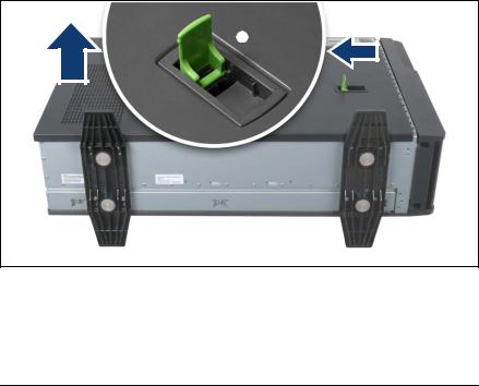
ÊIf necessary, lay the server on its right-hand side.
Get a second person to help you do this. The server can weigh around 25 - 40 kg (depending on the configuration).
Make sure that the server feet protrude over the table edge.
Figure 2: Removing the side cover
ÊPull the locking lever as far as it will go (1). This pushes the side cover backward (2).
ÊRemove the side cover (3).
28 |
Options Guide |
TX300 S6 |
Preparation |
Floorstand model |
4.1.2Removing the front cover
Remove the front cover when making the following routines:
–Installing/removing accessible drives
–Conversion from a floorstand model to a rack model
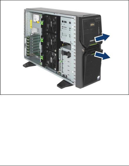
Figure 3: Removing the drive cover and the HDD cover
ÊUnlock the server and remove the key.
ÊRemove the drive cover (1).
ÊRemove the HDD cover (2).
TX300 S6 |
Options Guide |
29 |

Floorstand model |
Preparation |
|
|
Figure 4: Pulling out the locking buttons
Ê Pull out the two green locking buttons (1).
Figure 5: Removing the front cover
ÊPull the front cover forward slightly at the lower edge.
ÊUnhook the front cover at the top and remove it.
30 |
Options Guide |
TX300 S6 |
Loading...