


RX2530 M2
Table of contents
 Loading...
Upgrade and Maintenance Manual - English
FUJITSU Server PRIMERGY RX2530 M2
Upgrade and Maintenance Manual
March 2016

Comments… Suggestions… Corrections…
The User Documentation Department would like to
know your opinion of this manual. Your feedback helps
us optimize our documentation to suit your individual
needs.
Feel free to send us your comments by e-mail to
manuals@ts.fujitsu.com.
Certified documentation
according to DIN EN ISO 9001:2008
To ensure a consistently high quality standard and
user-friendliness, this documentation was created to
meet the regulations of a quality management system
which complies with the requirements of the standard
DIN EN ISO 9001:2008.
cognitas. Gesellschaft für Technik-Dokumentation mbH
www.cognitas.de
Copyright and Trademarks
Copyright © 2016 Fujitsu Technology Solutions GmbH.
All rights reserved.
Delivery subject to availability; right of technical modifications reserved.
All hardware and software names used are trademarks of their respective manufacturers.
– The contents of this manual may be revised without prior notice.
– Fujitsu assumes no liability for damages to third party copyrights or other rights arising from
the use of any information in this manual.
– No part of this manual may be reproduced in any form without the prior written permission
of Fujitsu.
Microsoft, Windows, Windows Server, and Hyper V are trademarks or registered trademarks of
Microsoft Corporation in the USA and other countries.
Intel and Xeon are trademarks or registered trademarks of Intel Corporation or its subsidiaries
in the USA and other countries.

Before reading this manual
For your safety
This manual contains important information for safely and correctly using this
product.
Carefully read the manual before using this product. Pay particular attention to
the accompanying manual "Safety Notes and Regulations" and ensure these
safety notes are understood before using the product. Keep this manual and the
manual "Safety Notes and Regulations" in a safe place for easy reference while
using this product.
Radio interference
This product is a "Class A" ITE (Information Technology Equipment). In a
domestic environment this product may cause radio interference, in which case
the user may be required to take appropriate measures. VCCI-A
Aluminum electrolytic capacitors
The aluminum electrolytic capacitors used in the product's printed circuit board
assemblies and in the mouse and keyboard are limited-life components. Use of
these components beyond their operating life may result in electrolyte leakage
or depletion, potentially causing emission of foul odor or smoke.
As a guideline, in a normal office environment (25°C) operating life is not
expected to be reached within the maintenance support period (5 years).
However, operating life may be reached more quickly if, for example, the
product is used in a hot environment. The customer shall bear the cost of
replacing replaceable components which have exceeded their operating life.
Note that these are only guidelines, and do not constitute a guarantee of
trouble-free operation during the maintenance support period.
High safety use
This product has been designed and manufactured to be used in commercial
and/or industrial areas as a server.
When used as visual display workplace, it must not be placed in the direct field
of view to avoid incommoding reflections (applies only to TX server systems).
The device has not been designed or manufactured for uses which demand an
extremely high level of safety and carry a direct and serious risk of life or body
if such safety cannot be assured.
RX2530 M2
Upgrade and Maintenance Manual

These uses include control of nuclear reactions in nuclear power plants,
automatic airplane flight control, air traffic control, traffic control in mass
transport systems, medical devices for life support, and missile guidance
control in weapons systems (hereafter, "high safety use"). Customers should
not use this product for high safety use unless measures are in place for
ensuring the level of safety demanded of such use. Please consult the sales
staff of Fujitsu if intending to use this product for high safety use.
Measures against momentary voltage drop
This product may be affected by a momentary voltage drop in the power supply
caused by lightning. To prevent a momentary voltage drop, use of an AC
uninterruptible power supply is recommended.
(This notice follows the guidelines of Voltage Dip Immunity of Personal
Computer issued by JEITA, the Japan Electronics and Information Technology
Industries Association.)
Technology controlled by the Foreign Exchange and Foreign Trade
Control Law of Japan
Documents produced by Fujitsu may contain technology controlled by the
Foreign Exchange and Foreign Trade Control Law of Japan. Documents which
contain such technology should not be exported from Japan or transferred to
non-residents of Japan without first obtaining authorization in accordance with
the above law.
Harmonic Current Standards
This product conforms to harmonic current standard JIS C 61000-3-2.
Only for the Japanese market: About SATA hard disk drives
The SATA version of this server supports hard disk drives with SATA / BC-SATA
storage interfaces. Please note that the usage and operation conditions differ
depending on the type of hard disk drive used.
Please refer to the following internet address for further information on the
usage and operation conditions of each available type of hard disk drive:
http://jp.fujitsu.com/platform/server/primergy/harddisk/
Only for the Japanese market:
Shielded LAN cables should be used in this product.
Upgrade and Maintenance Manual
RX2530 M2
Version history
Issue number Reason for update
1.0 / March 2016 Initial release
RX2530 M2
Upgrade and Maintenance Manual

Upgrade and Maintenance Manual
RX2530 M2

Contents
1 Introduction . . . . . . . . . . . . . . . . . . . . . . . . . . . 21
1.1 Notational conventions . . . . . . . . . . . . . . . . . . . . 22
2 Before you start . . . . . . . . . . . . . . . . . . . . . . . . 23
2.1 Classification of procedures . . . . . . . . . . . . . . . . . 25
2.1.1 Customer Replaceable Units (CRU) . . . . . . . . . . . . . . . 25
2.1.2 Upgrade and Repair Units (URU) . . . . . . . . . . . . . . . . 26
2.1.3 Field Replaceable Units (FRU) . . . . . . . . . . . . . . . . . 27
2.2 Average task duration . . . . . . . . . . . . . . . . . . . . . 28
2.3 Tools you need at hand . . . . . . . . . . . . . . . . . . . . 29
2.4 Documents you need at hand . . . . . . . . . . . . . . . . . 31
3 Important information . . . . . . . . . . . . . . . . . . . . . 33
3.1 Safety instructions . . . . . . . . . . . . . . . . . . . . . . . 33
3.2 ENERGY STAR . . . . . . . . . . . . . . . . . . . . . . . . . 41
3.3 CE conformity . . . . . . . . . . . . . . . . . . . . . . . . . 41
3.4 FCC Class A Compliance Statement . . . . . . . . . . . . . 42
3.5 Environmental protection . . . . . . . . . . . . . . . . . . . 43
4 Basic hardware procedures . . . . . . . . . . . . . . . . . . 45
4.1 Using diagnostics information . . . . . . . . . . . . . . . . 45
4.1.1 Locating the defective server . . . . . . . . . . . . . . . . . . 45
4.1.2 Determining the error class . . . . . . . . . . . . . . . . . . . 46
4.1.2.1 Global Error indicator . . . . . . . . . . . . . . . . . . . . 46
4.1.2.2 Customer Self Service (CSS) indicator . . . . . . . . . . . 46
4.1.3 Locating the defective component . . . . . . . . . . . . . . . . 47
4.1.3.1 Local diagnostic indicators on the system board . . . . . . . 47
4.2 Shutting down the server . . . . . . . . . . . . . . . . . . . 48
RX2530 M2
Upgrade and Maintenance Manual

Contents
4.3 Disconnecting the server from the mains . . . . . . . . . . . 49
4.4 Getting access to the component . . . . . . . . . . . . . . . 49
4.4.1 Extending the server out of the rack . . . . . . . . . . . . . . . 50
4.4.2 Removing the server from the rack . . . . . . . . . . . . . . . . 51
4.4.3 Removing the top covers . . . . . . . . . . . . . . . . . . . . . 53
4.5 Reassembling . . . . . . . . . . . . . . . . . . . . . . . . . . 54
4.5.1 Installing the top covers . . . . . . . . . . . . . . . . . . . . . . 54
4.5.2 Mounting the server in the rack . . . . . . . . . . . . . . . . . . 57
4.5.3 Sliding the server into the rack . . . . . . . . . . . . . . . . . . 59
4.6 Connecting the server to the mains . . . . . . . . . . . . . . 60
4.7 Switching on the server . . . . . . . . . . . . . . . . . . . . . 61
4.8 Handling riser modules . . . . . . . . . . . . . . . . . . . . . 62
4.8.1 Removing a riser module . . . . . . . . . . . . . . . . . . . . . 62
4.8.2 Installing a riser module . . . . . . . . . . . . . . . . . . . . . . 63
4.9 Handling fan sponges . . . . . . . . . . . . . . . . . . . . . . 65
4.9.1 Removing the fan sponges . . . . . . . . . . . . . . . . . . . . 66
4.9.2 Installing the fan sponges . . . . . . . . . . . . . . . . . . . . . 67
4.10 Handling CPU air guides . . . . . . . . . . . . . . . . . . . . 68
4.10.1 Removing the CPU air guides . . . . . . . . . . . . . . . . . . 68
4.10.2 Installing the CPU air guides . . . . . . . . . . . . . . . . . . . 69
5 Basic software procedures . . . . . . . . . . . . . . . . . . . 71
5.1 Starting the maintenance task . . . . . . . . . . . . . . . . . 71
5.1.1 Suspending BitLocker functionality . . . . . . . . . . . . . . . . 71
5.1.2 Disabling SVOM boot watchdog functionality . . . . . . . . . . . 72
5.1.2.1 Viewing boot watchdog settings . . . . . . . . . . . . . . . . 72
5.1.2.2 Configuring boot watchdog settings . . . . . . . . . . . . . . 73
5.1.3 Removing backup and optical disk media . . . . . . . . . . . . 74
5.1.4 Verifying and configuring the backup software solution . . . . . . 75
5.1.5 Note on server maintenance in a Multipath I/O environment . . . 75
5.1.6 Switching on the ID indicator . . . . . . . . . . . . . . . . . . . 78
5.2 Completing the maintenance task . . . . . . . . . . . . . . . 79
5.2.1 Updating or recovering the system board BIOS and iRMC . . . . 79
5.2.1.1 Updating or recovering the system board BIOS . . . . . . . . 79
5.2.1.2 Updating or recovering the iRMC . . . . . . . . . . . . . . . 79
5.2.2 Verifying system information backup / restore . . . . . . . . . . 81
Upgrade and Maintenance Manual
RX2530 M2

Contents
5.2.3 Updating RAID controller firmware . . . . . . . . . . . . . . . 82
5.2.4 Enabling Option ROM scan . . . . . . . . . . . . . . . . . . . 83
5.2.5 Verifying and configuring the backup software solution . . . . . 84
5.2.6 Resetting the boot retry counter . . . . . . . . . . . . . . . . . 84
5.2.6.1 Viewing the boot retry counter . . . . . . . . . . . . . . . . 84
5.2.6.2 Resetting the boot retry counter . . . . . . . . . . . . . . . 85
5.2.7 Resetting the error status after replacing memory modules or
processors . . . . . . . . . . . . . . . . . . . . . . . . . . . . 86
5.2.7.1 Memory modules . . . . . . . . . . . . . . . . . . . . . . . 86
5.2.7.2 Processors . . . . . . . . . . . . . . . . . . . . . . . . . . 88
5.2.8 Enabling SVOM boot watchdog functionality . . . . . . . . . . 89
5.2.9 Enabling replaced components in the system BIOS . . . . . . . 90
5.2.10 Verifying the memory mode . . . . . . . . . . . . . . . . . . . 91
5.2.11 Verifying the system time settings . . . . . . . . . . . . . . . . 91
5.2.12 Viewing and clearing the System Event Log (SEL) . . . . . . . 92
5.2.12.1 Viewing the SEL . . . . . . . . . . . . . . . . . . . . . . . 92
5.2.12.2 Clearing the SEL . . . . . . . . . . . . . . . . . . . . . . . 93
5.2.13 Updating the NIC configuration file in a Linux and VMware
environment . . . . . . . . . . . . . . . . . . . . . . . . . . . 93
5.2.14 Resuming BitLocker functionality . . . . . . . . . . . . . . . . 95
5.2.15 Performing a RAID array rebuild . . . . . . . . . . . . . . . . . 96
5.2.16 Looking up changed MAC / WWN addresses . . . . . . . . . . 96
5.2.16.1 Looking up MAC addresses . . . . . . . . . . . . . . . . . 96
5.2.16.2 Looking up WWN addresses . . . . . . . . . . . . . . . . . 97
5.2.17 Using the Chassis ID Prom Tool . . . . . . . . . . . . . . . . . 98
5.2.18 Configuring LAN teaming . . . . . . . . . . . . . . . . . . . . 99
5.2.18.1 After replacing / upgrading LAN controllers . . . . . . . . . 99
5.2.18.2 After replacing the system board . . . . . . . . . . . . . . . 99
5.2.19 Switching off the ID indicator . . . . . . . . . . . . . . . . . . 100
5.2.20 Performing a fan test . . . . . . . . . . . . . . . . . . . . . . 100
6 Power supply . . . . . . . . . . . . . . . . . . . . . . . . . . 103
6.1 Basic information . . . . . . . . . . . . . . . . . . . . . . . 104
6.1.1 Power supply unit configurations . . . . . . . . . . . . . . . . 105
6.1.2 Assembly rules . . . . . . . . . . . . . . . . . . . . . . . . . 105
6.2 Redundant power supply . . . . . . . . . . . . . . . . . . . 106
6.2.1 Installing a power supply unit . . . . . . . . . . . . . . . . . . 106
6.2.1.1 Preliminary steps . . . . . . . . . . . . . . . . . . . . . . . 106
6.2.1.2 Removing the dummy cover . . . . . . . . . . . . . . . . . 106
RX2530 M2
Upgrade and Maintenance Manual

Contents
6.2.1.3 Installing a power supply unit . . . . . . . . . . . . . . . . 107
6.2.1.4 Concluding steps . . . . . . . . . . . . . . . . . . . . . . 108
6.2.2 Removing a power supply unit . . . . . . . . . . . . . . . . . 109
6.2.2.1 Preliminary steps . . . . . . . . . . . . . . . . . . . . . . 111
6.2.2.2 Removing a power supply unit . . . . . . . . . . . . . . . 111
6.2.2.3 Installing the dummy cover . . . . . . . . . . . . . . . . . 112
6.2.3 Replacing a power supply unit . . . . . . . . . . . . . . . . . 112
6.2.3.1 Preliminary steps . . . . . . . . . . . . . . . . . . . . . . 113
6.2.3.2 Removing the defective power supply unit . . . . . . . . . 113
6.2.3.3 Installing the new power supply unit . . . . . . . . . . . . 114
6.2.3.4 Concluding steps . . . . . . . . . . . . . . . . . . . . . . 114
7 Hard disk drives / solid state drives . . . . . . . . . . . . . 115
7.1 Basic information . . . . . . . . . . . . . . . . . . . . . . . 116
7.2 2.5-inch HDD/SSD configurations . . . . . . . . . . . . . . 117
7.2.1 Equipping the 2.5-inch HDD/SSD bays . . . . . . . . . . . . . 117
7.2.2 Configuration with up to four HDD/SSD modules . . . . . . . . 117
7.2.3 Configuration with up to eight HDD/SSD modules . . . . . . . 118
7.2.4 Configuration with up to 10 HDD/SSD modules . . . . . . . . 120
7.2.5 Installing 2.5-inch HDD/SSD modules . . . . . . . . . . . . . 123
7.2.5.1 Preliminary steps . . . . . . . . . . . . . . . . . . . . . . 123
7.2.5.2 Removing a 2.5-inch HDD/SSD dummy module . . . . . . 123
7.2.5.3 Installing a 2.5-inch HDD/SSD module . . . . . . . . . . . 124
7.2.5.4 Concluding steps . . . . . . . . . . . . . . . . . . . . . . 125
7.2.6 Removing 2.5-inch HDD/SSD modules . . . . . . . . . . . . . 126
7.2.6.1 Preliminary steps . . . . . . . . . . . . . . . . . . . . . . 126
7.2.6.2 Removing a 2.5-inch HDD/SSD module . . . . . . . . . . 127
7.2.6.3 Installing a 2.5-inch HDD/SSD dummy module . . . . . . . 127
7.2.6.4 Concluding steps . . . . . . . . . . . . . . . . . . . . . . 127
7.2.7 Replacing a 2.5-inch HDD/SSD module . . . . . . . . . . . . 128
7.2.7.1 Preliminary steps . . . . . . . . . . . . . . . . . . . . . . 128
7.2.7.2 Removing the defective 2.5-inch HDD/SSD module . . . . 128
7.2.7.3 Installing the new 2.5-inch HDD/SSD module . . . . . . . . 129
7.2.7.4 Concluding steps . . . . . . . . . . . . . . . . . . . . . . 129
7.2.8 Replacing the 4 x 2.5-inch HDD backplane . . . . . . . . . . . 129
7.2.8.1 Preliminary steps . . . . . . . . . . . . . . . . . . . . . . 129
7.2.8.2 Removing the defective 4 x 2.5-inch HDD backplane . . . . 130
7.2.8.3 Installing the new 4 x 2.5-inch HDD backplane . . . . . . . 133
7.2.8.4 Concluding steps . . . . . . . . . . . . . . . . . . . . . . 135
Upgrade and Maintenance Manual
RX2530 M2

Contents
7.2.9 Replacing the 10 x 2.5-inch HDD backplane . . . . . . . . . . 136
7.2.9.1 Preliminary steps . . . . . . . . . . . . . . . . . . . . . . . 136
7.2.9.2 Removing the SAS expander board . . . . . . . . . . . . . 137
7.2.9.3 Removing the defective 10 x 2.5-inch HDD backplane . . . 139
7.2.9.4 Installing the new 10 x 2.5-inch HDD backplane . . . . . . . 139
7.2.9.5 Installing the SAS expander board . . . . . . . . . . . . . . 140
7.2.9.6 Concluding steps . . . . . . . . . . . . . . . . . . . . . . . 141
7.2.10 Replacing the SAS expander board . . . . . . . . . . . . . . . 142
7.2.10.1 Preliminary steps . . . . . . . . . . . . . . . . . . . . . . . 142
7.2.10.2 Removing the defective SAS expander board . . . . . . . . 142
7.2.10.3 Installing the new SAS expander board . . . . . . . . . . . 142
7.2.10.4 Concluding steps . . . . . . . . . . . . . . . . . . . . . . . 142
7.2.11 Upgrading configuration from up to four to up to eight 2.5-inch
HDDs/SSDs . . . . . . . . . . . . . . . . . . . . . . . . . . . 143
7.2.11.1 Preliminary steps . . . . . . . . . . . . . . . . . . . . . . . 143
7.2.11.2 Installing the second HDD backplane . . . . . . . . . . . . 143
7.2.11.3 Installing additional HDD/SSD modules . . . . . . . . . . . 144
7.2.11.4 Concluding steps . . . . . . . . . . . . . . . . . . . . . . . 144
7.3 3.5-inch HDD configurations . . . . . . . . . . . . . . . . . 145
7.3.1 Equipping the 3.5-inch HDD bays . . . . . . . . . . . . . . . . 145
7.3.2 Installing 3.5-inch HDD modules . . . . . . . . . . . . . . . . 146
7.3.2.1 Preliminary steps . . . . . . . . . . . . . . . . . . . . . . . 146
7.3.2.2 Removing a 3.5-inch HDD dummy module . . . . . . . . . 146
7.3.2.3 Installing a 3.5-inch HDD module . . . . . . . . . . . . . . 147
7.3.2.4 Concluding steps . . . . . . . . . . . . . . . . . . . . . . . 147
7.3.3 Removing 3.5-inch HDD modules . . . . . . . . . . . . . . . . 148
7.3.3.1 Preliminary steps . . . . . . . . . . . . . . . . . . . . . . . 148
7.3.3.2 Removing a 3.5-inch HDD module . . . . . . . . . . . . . . 149
7.3.3.3 Installing a 3.5-inch dummy module . . . . . . . . . . . . . 149
7.3.3.4 Concluding steps . . . . . . . . . . . . . . . . . . . . . . . 149
7.3.4 Replacing a 3.5-inch HDD module . . . . . . . . . . . . . . . 150
7.3.4.1 Preliminary steps . . . . . . . . . . . . . . . . . . . . . . . 150
7.3.4.2 Removing the defective 3.5-inch HDD module . . . . . . . 151
7.3.4.3 Installing the new 3.5-inch HDD module . . . . . . . . . . . 151
7.3.4.4 Concluding steps . . . . . . . . . . . . . . . . . . . . . . . 151
7.3.5 Replacing the 3.5-inch HDD backplane . . . . . . . . . . . . . 151
7.3.5.1 Preliminary steps . . . . . . . . . . . . . . . . . . . . . . . 151
7.3.5.2 Removing the defective 3.5-inch HDD backplane . . . . . . 152
7.3.5.3 Installing the new 3.5-inch HDD backplane . . . . . . . . . 153
7.3.5.4 Concluding steps . . . . . . . . . . . . . . . . . . . . . . . 154
RX2530 M2
Upgrade and Maintenance Manual

Contents
8 Fans . . . . . . . . . . . . . . . . . . . . . . . . . . . . . . 155
8.1 Basic information . . . . . . . . . . . . . . . . . . . . . . . 155
8.1.1 Numbering of the fan modules . . . . . . . . . . . . . . . . . 156
8.2 Replacing a defective fan module . . . . . . . . . . . . . . 158
8.2.1 Preliminary steps . . . . . . . . . . . . . . . . . . . . . . . . 158
8.2.2 Removing the defective fan module . . . . . . . . . . . . . . 158
8.2.3 Installing the new fan module . . . . . . . . . . . . . . . . . . 159
8.2.4 Concluding steps . . . . . . . . . . . . . . . . . . . . . . . . 160
9 Expansion cards and backup units . . . . . . . . . . . . . 161
9.1 Basic information . . . . . . . . . . . . . . . . . . . . . . . 162
9.1.1 Equipping the PCIe slots . . . . . . . . . . . . . . . . . . . . 162
9.1.2 Equipping the slot for DynamicLoM modules . . . . . . . . . . 165
9.1.2.1 PLAN EM 2x 1GB T . . . . . . . . . . . . . . . . . . . . . 166
9.1.2.2 PLAN EM 4x 1GB T . . . . . . . . . . . . . . . . . . . . . 167
9.1.2.3 PLAN EM 2x 10 GB SFP . . . . . . . . . . . . . . . . . . 168
9.1.2.4 PLAN EM 2x 10 GB T . . . . . . . . . . . . . . . . . . . . 169
9.2 Handling slot brackets . . . . . . . . . . . . . . . . . . . . 170
9.2.1 Installing a slot bracket . . . . . . . . . . . . . . . . . . . . . 170
9.2.2 Removing a slot bracket . . . . . . . . . . . . . . . . . . . . 172
9.2.2.1 Removing the slot bracket . . . . . . . . . . . . . . . . . . 172
9.3 Handling SFP+ transceiver modules . . . . . . . . . . . . . 173
9.3.1 Installing SFP+ transceiver modules . . . . . . . . . . . . . . 173
9.3.2 Removing an SFP+ transceiver module . . . . . . . . . . . . 176
9.4 DynamicLoM modules . . . . . . . . . . . . . . . . . . . . 179
9.4.1 Installing a DynamicLoM module . . . . . . . . . . . . . . . . 179
9.4.1.1 Preliminary steps . . . . . . . . . . . . . . . . . . . . . . 179
9.4.1.2 Removing the dummy cover . . . . . . . . . . . . . . . . 179
9.4.1.3 Installing the DynamicLoM module . . . . . . . . . . . . . 180
9.4.1.4 Concluding steps . . . . . . . . . . . . . . . . . . . . . . 182
9.4.1.5 Software configuration . . . . . . . . . . . . . . . . . . . 183
9.4.2 Removing the DynamicLoM module . . . . . . . . . . . . . . 184
9.4.2.1 Preliminary steps . . . . . . . . . . . . . . . . . . . . . . 184
9.4.2.2 Removing the DynamicLoM module . . . . . . . . . . . . 184
9.4.2.3 Installing the dummy cover . . . . . . . . . . . . . . . . . 185
9.4.2.4 Concluding steps . . . . . . . . . . . . . . . . . . . . . . 185
9.4.3 Replacing the DynamicLoM module . . . . . . . . . . . . . . 186
Upgrade and Maintenance Manual
RX2530 M2

Contents
9.4.3.1 Preliminary steps . . . . . . . . . . . . . . . . . . . . . . . 186
9.4.3.2 Removing the defective DynamicLoM module . . . . . . . . 186
9.4.3.3 Installing the new DynamicLoM module . . . . . . . . . . . 186
9.4.3.4 Concluding steps . . . . . . . . . . . . . . . . . . . . . . . 186
9.4.3.5 Software configuration . . . . . . . . . . . . . . . . . . . . 187
9.5 Expansion cards and riser cards . . . . . . . . . . . . . . . 188
9.5.1 Installing an expansion card . . . . . . . . . . . . . . . . . . . 189
9.5.1.1 Preliminary steps . . . . . . . . . . . . . . . . . . . . . . . 189
9.5.1.2 Removing the slot cover (only slot 2-4) . . . . . . . . . . . 190
9.5.1.3 Installing the expansion card . . . . . . . . . . . . . . . . . 190
9.5.1.4 Concluding steps . . . . . . . . . . . . . . . . . . . . . . . 192
9.5.2 Removing an expansion card . . . . . . . . . . . . . . . . . . 192
9.5.2.1 Preliminary steps . . . . . . . . . . . . . . . . . . . . . . . 192
9.5.2.2 Removing the expansion card . . . . . . . . . . . . . . . . 193
9.5.2.3 Installing the slot cover (only slot 2-4) . . . . . . . . . . . . 193
9.5.2.4 Concluding steps . . . . . . . . . . . . . . . . . . . . . . . 194
9.5.3 Replacing an expansion card . . . . . . . . . . . . . . . . . . 194
9.5.3.1 Preliminary steps . . . . . . . . . . . . . . . . . . . . . . . 194
9.5.3.2 Removing the defective expansion card . . . . . . . . . . . 195
9.5.3.3 Installing the new expansion card . . . . . . . . . . . . . . 195
9.5.3.4 Concluding steps . . . . . . . . . . . . . . . . . . . . . . . 195
9.5.4 Replacing a riser card . . . . . . . . . . . . . . . . . . . . . . 197
9.5.4.1 Preliminary steps . . . . . . . . . . . . . . . . . . . . . . . 197
9.5.4.2 Removing the defective riser card . . . . . . . . . . . . . . 197
9.5.4.3 Installing the new riser card . . . . . . . . . . . . . . . . . 198
9.5.4.4 Concluding steps . . . . . . . . . . . . . . . . . . . . . . . 198
9.5.5 Replacing a TFM . . . . . . . . . . . . . . . . . . . . . . . . 199
9.5.5.1 Preliminary steps . . . . . . . . . . . . . . . . . . . . . . . 199
9.5.5.2 Removing the defective TFM . . . . . . . . . . . . . . . . 199
9.5.5.3 Installing the new TFM . . . . . . . . . . . . . . . . . . . . 201
9.5.5.4 Concluding steps . . . . . . . . . . . . . . . . . . . . . . . 202
9.5.6 Upgrading to the full height riser module . . . . . . . . . . . . 203
9.5.6.1 Preliminary steps . . . . . . . . . . . . . . . . . . . . . . . 203
9.5.6.2 Installing the upgrade kit . . . . . . . . . . . . . . . . . . . 204
9.6 Flash Backup unit . . . . . . . . . . . . . . . . . . . . . . . 207
9.6.1 Installing an FBU in a 2.5-inch HDD chassis . . . . . . . . . . 207
9.6.1.1 Preliminary steps . . . . . . . . . . . . . . . . . . . . . . . 207
9.6.1.2 Preparing the FBU . . . . . . . . . . . . . . . . . . . . . . 207
9.6.1.3 Installing the FBU . . . . . . . . . . . . . . . . . . . . . . 208
9.6.1.4 Concluding steps . . . . . . . . . . . . . . . . . . . . . . . 210
9.6.2 Installing an FBU in a 3.5-inch HDD chassis . . . . . . . . . . 210
RX2530 M2
Upgrade and Maintenance Manual

Contents
9.6.2.1 Preliminary steps . . . . . . . . . . . . . . . . . . . . . . 210
9.6.2.2 Preparing the riser holder . . . . . . . . . . . . . . . . . . 211
9.6.2.3 Preparing the FBU . . . . . . . . . . . . . . . . . . . . . 212
9.6.2.4 Installing the FBU . . . . . . . . . . . . . . . . . . . . . . 213
9.6.2.5 Concluding steps . . . . . . . . . . . . . . . . . . . . . . 215
9.6.3 Removing an FBU from a 2.5-inch HDD chassis . . . . . . . . 215
9.6.3.1 Preliminary steps . . . . . . . . . . . . . . . . . . . . . . 215
9.6.3.2 Removing the FBU with the holder . . . . . . . . . . . . . 216
9.6.3.3 Disconnecting the FBU cable from the FBU . . . . . . . . 216
9.6.3.4 Removing the FBU from the holder . . . . . . . . . . . . . 216
9.6.3.5 Concluding steps . . . . . . . . . . . . . . . . . . . . . . 216
9.6.4 Removing an FBU from a 3.5-inch HDD chassis . . . . . . . . 217
9.6.4.1 Preliminary steps . . . . . . . . . . . . . . . . . . . . . . 217
9.6.4.2 Removing the FBU with the holder . . . . . . . . . . . . . 218
9.6.4.3 Disconnecting the FBU cable from the FBU . . . . . . . . 218
9.6.4.4 Removing the FBU from the holder . . . . . . . . . . . . . 219
9.6.4.5 Concluding steps . . . . . . . . . . . . . . . . . . . . . . 219
9.6.5 Replacing an FBU . . . . . . . . . . . . . . . . . . . . . . . 220
9.6.5.1 Preliminary steps . . . . . . . . . . . . . . . . . . . . . . 220
9.6.5.2 Removing the defective FBU . . . . . . . . . . . . . . . . 220
9.6.5.3 Installing the new FBU . . . . . . . . . . . . . . . . . . . 220
9.6.5.4 Concluding steps . . . . . . . . . . . . . . . . . . . . . . 221
10 Main memory . . . . . . . . . . . . . . . . . . . . . . . . . 223
10.1 Basic information . . . . . . . . . . . . . . . . . . . . . . . 224
10.1.1 Population rules . . . . . . . . . . . . . . . . . . . . . . . . . 226
10.1.2 Modes of operation . . . . . . . . . . . . . . . . . . . . . . . 227
10.1.2.1 Independent Channel mode . . . . . . . . . . . . . . . . . 227
10.1.2.2 Mirrored Channel and Performance modes . . . . . . . . . 228
10.1.2.3 Rank Sparing mode . . . . . . . . . . . . . . . . . . . . . 229
10.2 Installing a memory module . . . . . . . . . . . . . . . . . 233
10.2.1 Preliminary steps . . . . . . . . . . . . . . . . . . . . . . . . 233
10.2.2 Selecting the memory slot . . . . . . . . . . . . . . . . . . . 233
10.2.3 Installing a memory module . . . . . . . . . . . . . . . . . . . 234
10.2.4 Concluding steps . . . . . . . . . . . . . . . . . . . . . . . . 234
10.3 Removing a memory module . . . . . . . . . . . . . . . . . 235
10.3.1 Preliminary steps . . . . . . . . . . . . . . . . . . . . . . . . 235
10.3.2 Removing a memory module . . . . . . . . . . . . . . . . . . 235
10.3.3 Concluding steps . . . . . . . . . . . . . . . . . . . . . . . . 236
Upgrade and Maintenance Manual
RX2530 M2

Contents
10.4 Replacing a memory module . . . . . . . . . . . . . . . . . 236
10.4.1 Preliminary steps . . . . . . . . . . . . . . . . . . . . . . . . 236
10.4.2 Removing the defective memory module . . . . . . . . . . . . 236
10.4.3 Installing the new memory module . . . . . . . . . . . . . . . 237
10.4.4 Concluding steps . . . . . . . . . . . . . . . . . . . . . . . . 237
11 Processors . . . . . . . . . . . . . . . . . . . . . . . . . . . 239
11.1 Basic information . . . . . . . . . . . . . . . . . . . . . . . 240
11.1.1 Supported processors . . . . . . . . . . . . . . . . . . . . . . 241
11.1.2 General equipping rules . . . . . . . . . . . . . . . . . . . . . 241
11.2 Upgrading to dual processor configuration . . . . . . . . . 241
11.2.1 Preliminary steps . . . . . . . . . . . . . . . . . . . . . . . . 242
11.2.2 Installing the processor . . . . . . . . . . . . . . . . . . . . . 242
11.2.3 Installing the heat sink . . . . . . . . . . . . . . . . . . . . . . 248
11.2.4 Upgrading the main memory . . . . . . . . . . . . . . . . . . 249
11.2.5 Installing four additional fan modules . . . . . . . . . . . . . . 250
11.2.6 Concluding steps . . . . . . . . . . . . . . . . . . . . . . . . 250
11.3 Replacing a processor . . . . . . . . . . . . . . . . . . . . . 251
11.3.1 Preliminary steps . . . . . . . . . . . . . . . . . . . . . . . . 251
11.3.2 Removing the heat sink . . . . . . . . . . . . . . . . . . . . . 252
11.3.3 Removing the defective processor . . . . . . . . . . . . . . . 253
11.3.4 Installing the new processor . . . . . . . . . . . . . . . . . . . 256
11.3.5 Applying the thermal paste to the processor surface . . . . . . 256
11.3.6 Installing the heat sink . . . . . . . . . . . . . . . . . . . . . . 257
11.3.7 Concluding steps . . . . . . . . . . . . . . . . . . . . . . . . 258
11.4 Replacing the heat sink . . . . . . . . . . . . . . . . . . . . 258
11.4.1 Preliminary steps . . . . . . . . . . . . . . . . . . . . . . . . 258
11.4.2 Removing the defective heat sink . . . . . . . . . . . . . . . . 259
11.4.3 Installing the new heat sink . . . . . . . . . . . . . . . . . . . 259
11.4.4 Concluding steps . . . . . . . . . . . . . . . . . . . . . . . . 259
12 Optical disk drive . . . . . . . . . . . . . . . . . . . . . . . . 261
12.1 Basic information . . . . . . . . . . . . . . . . . . . . . . . 262
12.2 Installing the ODD . . . . . . . . . . . . . . . . . . . . . . . 264
12.2.1 Preliminary steps . . . . . . . . . . . . . . . . . . . . . . . . 264
12.2.2 Removing the dummy cover . . . . . . . . . . . . . . . . . . . 265
12.2.3 Installing the ODD . . . . . . . . . . . . . . . . . . . . . . . . 265
RX2530 M2
Upgrade and Maintenance Manual

Contents
12.2.4 Concluding steps . . . . . . . . . . . . . . . . . . . . . . . . 267
12.3 Removing the ODD . . . . . . . . . . . . . . . . . . . . . . 268
12.3.1 Preliminary steps . . . . . . . . . . . . . . . . . . . . . . . . 268
12.3.2 Removing the ODD . . . . . . . . . . . . . . . . . . . . . . . 268
12.3.3 Installing the dummy cover . . . . . . . . . . . . . . . . . . . 270
12.3.4 Concluding steps . . . . . . . . . . . . . . . . . . . . . . . . 270
12.4 Replacing the ODD . . . . . . . . . . . . . . . . . . . . . . 271
12.4.1 Preliminary steps . . . . . . . . . . . . . . . . . . . . . . . . 271
12.4.2 Removing the defective ODD . . . . . . . . . . . . . . . . . . 271
12.4.3 Installing the new ODD . . . . . . . . . . . . . . . . . . . . . 271
12.4.4 Concluding steps . . . . . . . . . . . . . . . . . . . . . . . . 271
13 Front panel . . . . . . . . . . . . . . . . . . . . . . . . . . . 273
13.1 Basic information . . . . . . . . . . . . . . . . . . . . . . . 273
13.2 Front panel module . . . . . . . . . . . . . . . . . . . . . . 274
13.2.1 Replacing the front panel module . . . . . . . . . . . . . . . . 274
13.2.1.1 Preliminary steps . . . . . . . . . . . . . . . . . . . . . . 274
13.2.1.2 Removing the front panel module . . . . . . . . . . . . . . 275
13.2.1.3 Installing the front panel module . . . . . . . . . . . . . . 278
13.2.1.4 Concluding steps . . . . . . . . . . . . . . . . . . . . . . 280
13.3 Front VGA board . . . . . . . . . . . . . . . . . . . . . . . . 280
13.3.1 Installing the front VGA board . . . . . . . . . . . . . . . . . 280
13.3.1.1 Preliminary steps . . . . . . . . . . . . . . . . . . . . . . 280
13.3.1.2 Removing the dummy cover . . . . . . . . . . . . . . . . 281
13.3.1.3 Installing the front VGA board . . . . . . . . . . . . . . . . 281
13.3.1.4 Concluding steps . . . . . . . . . . . . . . . . . . . . . . 282
13.3.2 Removing the front VGA board . . . . . . . . . . . . . . . . . 282
13.3.2.1 Preliminary steps . . . . . . . . . . . . . . . . . . . . . . 282
13.3.2.2 Removing the front VGA board . . . . . . . . . . . . . . . 283
13.3.2.3 Installing the dummy cover . . . . . . . . . . . . . . . . . 283
13.3.2.4 Concluding steps . . . . . . . . . . . . . . . . . . . . . . 283
13.3.3 Replacing the front VGA board . . . . . . . . . . . . . . . . . 284
13.3.3.1 Preliminary steps . . . . . . . . . . . . . . . . . . . . . . 284
13.3.3.2 Removing the defective front VGA board . . . . . . . . . . 284
13.3.3.3 Installing the new front VGA board . . . . . . . . . . . . . 284
13.3.3.4 Concluding steps . . . . . . . . . . . . . . . . . . . . . . 284
13.4 Front panel on QRL (10 x 2.5-inch HDD configuration) . . . 285
13.4.1 Replacing the front panel on QRL . . . . . . . . . . . . . . . 285
Upgrade and Maintenance Manual
RX2530 M2

Contents
13.4.1.1 Preliminary steps . . . . . . . . . . . . . . . . . . . . . . . 285
13.4.1.2 Removing the front panel on QRL . . . . . . . . . . . . . . 286
13.4.1.3 Installing the front panel on QRL . . . . . . . . . . . . . . . 287
13.4.1.4 Concluding steps . . . . . . . . . . . . . . . . . . . . . . . 289
14 Serial interface . . . . . . . . . . . . . . . . . . . . . . . . . 291
14.1 Installing the serial interface . . . . . . . . . . . . . . . . . 291
14.1.1 Preliminary steps . . . . . . . . . . . . . . . . . . . . . . . . 292
14.1.2 Removing the slot cover . . . . . . . . . . . . . . . . . . . . . 292
14.1.3 Installing the serial interface . . . . . . . . . . . . . . . . . . . 292
14.1.4 Concluding steps . . . . . . . . . . . . . . . . . . . . . . . . 293
14.2 Removing the serial interface . . . . . . . . . . . . . . . . . 294
14.2.1 Preliminary steps . . . . . . . . . . . . . . . . . . . . . . . . 294
14.2.2 Removing the serial interface . . . . . . . . . . . . . . . . . . 294
14.2.3 Installing the slot cover . . . . . . . . . . . . . . . . . . . . . 295
14.2.4 Concluding steps . . . . . . . . . . . . . . . . . . . . . . . . 295
14.3 Replacing the serial interface . . . . . . . . . . . . . . . . . 296
14.3.1 Preliminary steps . . . . . . . . . . . . . . . . . . . . . . . . 296
14.3.2 Removing the defective serial interface . . . . . . . . . . . . . 296
14.3.3 Installing the new serial interface . . . . . . . . . . . . . . . . 296
14.3.4 Concluding steps . . . . . . . . . . . . . . . . . . . . . . . . 296
15 System board and components . . . . . . . . . . . . . . . . 297
15.1 Basic information . . . . . . . . . . . . . . . . . . . . . . . 297
15.2 CMOS battery . . . . . . . . . . . . . . . . . . . . . . . . . . 298
15.2.1 Replacing the CMOS battery . . . . . . . . . . . . . . . . . . 298
15.2.1.1 Preliminary steps . . . . . . . . . . . . . . . . . . . . . . . 299
15.2.1.2 Replacing the defective CMOS battery . . . . . . . . . . . 299
15.2.1.3 Concluding steps . . . . . . . . . . . . . . . . . . . . . . . 300
15.3 USB Flash Module (UFM) . . . . . . . . . . . . . . . . . . . 300
15.3.1 Installing the UFM . . . . . . . . . . . . . . . . . . . . . . . . 300
15.3.1.1 Preliminary steps . . . . . . . . . . . . . . . . . . . . . . . 300
15.3.1.2 Installing the UFM . . . . . . . . . . . . . . . . . . . . . . 301
15.3.1.3 Concluding steps . . . . . . . . . . . . . . . . . . . . . . . 302
15.3.1.4 Software configuration . . . . . . . . . . . . . . . . . . . . 302
15.3.2 Removing the UFM . . . . . . . . . . . . . . . . . . . . . . . 303
15.3.2.1 Preliminary steps . . . . . . . . . . . . . . . . . . . . . . . 303
RX2530 M2
Upgrade and Maintenance Manual

Contents
15.3.2.2 Removing the UFM . . . . . . . . . . . . . . . . . . . . . 304
15.3.2.3 Concluding steps . . . . . . . . . . . . . . . . . . . . . . 305
15.3.3 Replacing the UFM . . . . . . . . . . . . . . . . . . . . . . . 306
15.3.3.1 Preliminary steps . . . . . . . . . . . . . . . . . . . . . . 306
15.3.3.2 Removing the defective UFM . . . . . . . . . . . . . . . . 306
15.3.3.3 Installing the new UFM . . . . . . . . . . . . . . . . . . . 307
15.3.3.4 Concluding steps . . . . . . . . . . . . . . . . . . . . . . 308
15.3.3.5 Software configuration . . . . . . . . . . . . . . . . . . . 308
15.4 Trusted Platform Module (TPM) . . . . . . . . . . . . . . . . 309
15.4.1 Installing the TPM . . . . . . . . . . . . . . . . . . . . . . . . 309
15.4.1.1 Preliminary steps . . . . . . . . . . . . . . . . . . . . . . 309
15.4.1.2 Installing the TPM . . . . . . . . . . . . . . . . . . . . . . 310
15.4.1.3 Concluding steps . . . . . . . . . . . . . . . . . . . . . . 312
15.4.2 Removing the TPM . . . . . . . . . . . . . . . . . . . . . . . 313
15.4.2.1 Preliminary steps . . . . . . . . . . . . . . . . . . . . . . 313
15.4.2.2 Removing the TPM . . . . . . . . . . . . . . . . . . . . . 315
15.4.2.3 Concluding steps . . . . . . . . . . . . . . . . . . . . . . 316
15.4.3 Replacing the TPM . . . . . . . . . . . . . . . . . . . . . . . 317
15.4.3.1 Preliminary steps . . . . . . . . . . . . . . . . . . . . . . 317
15.4.3.2 Removing the defective TPM . . . . . . . . . . . . . . . . 318
15.4.3.3 Installing the new TPM . . . . . . . . . . . . . . . . . . . 318
15.4.3.4 Concluding steps . . . . . . . . . . . . . . . . . . . . . . 318
15.5 SATA DOM . . . . . . . . . . . . . . . . . . . . . . . . . . . 319
15.5.1 Installing the SATA DOM . . . . . . . . . . . . . . . . . . . . 319
15.5.1.1 Preliminary steps . . . . . . . . . . . . . . . . . . . . . . 319
15.5.1.2 Installing the SATA DOM . . . . . . . . . . . . . . . . . . 319
15.5.1.3 Concluding steps . . . . . . . . . . . . . . . . . . . . . . 320
15.5.2 Removing the SATA DOM . . . . . . . . . . . . . . . . . . . 321
15.5.2.1 Preliminary steps . . . . . . . . . . . . . . . . . . . . . . 321
15.5.2.2 Removing the SATA DOM . . . . . . . . . . . . . . . . . . 321
15.5.2.3 Concluding steps . . . . . . . . . . . . . . . . . . . . . . 321
15.5.3 Replacing the SATA DOM . . . . . . . . . . . . . . . . . . . 322
15.5.3.1 Preliminary steps . . . . . . . . . . . . . . . . . . . . . . 322
15.5.3.2 Replacing the SATA DOM . . . . . . . . . . . . . . . . . . 322
15.5.3.3 Concluding steps . . . . . . . . . . . . . . . . . . . . . . 322
15.6 iRMC microSD card . . . . . . . . . . . . . . . . . . . . . . 323
15.6.1 Installing the iRMC microSD card . . . . . . . . . . . . . . . . 323
15.6.1.1 Preliminary steps . . . . . . . . . . . . . . . . . . . . . . 323
15.6.1.2 Installing the iRMC microSD card . . . . . . . . . . . . . . 323
15.6.1.3 Concluding steps . . . . . . . . . . . . . . . . . . . . . . 324
15.6.2 Removing the iRMC microSD card . . . . . . . . . . . . . . . 324
Upgrade and Maintenance Manual
RX2530 M2

Contents
15.6.2.1 Preliminary steps . . . . . . . . . . . . . . . . . . . . . . . 324
15.6.2.2 Removing the iRMC microSD card . . . . . . . . . . . . . 325
15.6.2.3 Concluding steps . . . . . . . . . . . . . . . . . . . . . . . 325
15.6.3 Replacing the iRMC microSD card . . . . . . . . . . . . . . . 325
15.6.3.1 Preliminary steps . . . . . . . . . . . . . . . . . . . . . . . 326
15.6.3.2 Replacing the iRMC microSD card . . . . . . . . . . . . . . 326
15.6.3.3 Concluding steps . . . . . . . . . . . . . . . . . . . . . . . 326
15.7 System board . . . . . . . . . . . . . . . . . . . . . . . . . . 327
15.7.1 Replacing the system board . . . . . . . . . . . . . . . . . . . 327
15.7.1.1 Preliminary steps . . . . . . . . . . . . . . . . . . . . . . . 329
15.7.1.2 Removing the defective system board . . . . . . . . . . . . 330
15.7.1.3 Installing the new system board . . . . . . . . . . . . . . . 331
15.7.1.4 Concluding steps . . . . . . . . . . . . . . . . . . . . . . . 333
16 Cables . . . . . . . . . . . . . . . . . . . . . . . . . . . . . . 335
16.1 Overview cables . . . . . . . . . . . . . . . . . . . . . . . . 335
16.2 Cabling . . . . . . . . . . . . . . . . . . . . . . . . . . . . . 337
17 Appendix . . . . . . . . . . . . . . . . . . . . . . . . . . . . 351
17.1 Mechanical overview . . . . . . . . . . . . . . . . . . . . . . 351
17.1.1 Server front . . . . . . . . . . . . . . . . . . . . . . . . . . . 351
17.1.2 Server rear . . . . . . . . . . . . . . . . . . . . . . . . . . . . 353
17.1.3 Server interior . . . . . . . . . . . . . . . . . . . . . . . . . . 354
17.2 Connectors and indicators . . . . . . . . . . . . . . . . . . 356
17.2.1 Connectors and indicators on the system board . . . . . . . . 356
17.2.1.1 Onboard connectors . . . . . . . . . . . . . . . . . . . . . 356
17.2.1.2 Onboard indicators and controls . . . . . . . . . . . . . . . 358
17.2.1.3 I/O panel connectors . . . . . . . . . . . . . . . . . . . . . 360
17.2.1.4 I/O panel indicators . . . . . . . . . . . . . . . . . . . . . . 361
17.2.1.5 Indicators on power supply units (slide-in units) . . . . . . . 362
17.2.2 Indicators on the front panel . . . . . . . . . . . . . . . . . . . 363
17.2.3 Indicators on the accessible drives/components . . . . . . . . 366
17.3 Onboard settings . . . . . . . . . . . . . . . . . . . . . . . . 368
17.4 Minimum startup configuration . . . . . . . . . . . . . . . . 369
RX2530 M2
Upgrade and Maintenance Manual

Contents
Upgrade and Maintenance Manual
RX2530 M2

1 Introduction
This Upgrade and Maintenance Manual provides instructions for the following
procedures:
●
Upgrading the server configuration by adding optional hardware
components
●
Upgrading the server configuration by replacing existing hardware
components with superior ones.
●
Replacing defective hardware components
This manual focuses on on-site maintenance tasks. It is recommended to
prepare each service assignment following remote diagnostics procedures, as
described in the "ServerView Suite Local Service Concept (LSC)" manual (see
section "Documents you need at hand" on page 31.
V
CAUTION!
The document at hand comprises procedures of a wide range of
complexity. Check the profile of qualification for technicians before
assigning tasks. Before you start, carefully read "Classification of
procedures" on page 25.
RX2530 M2
Upgrade and Maintenance Manual 21
Introduction
1.1 Notational conventions
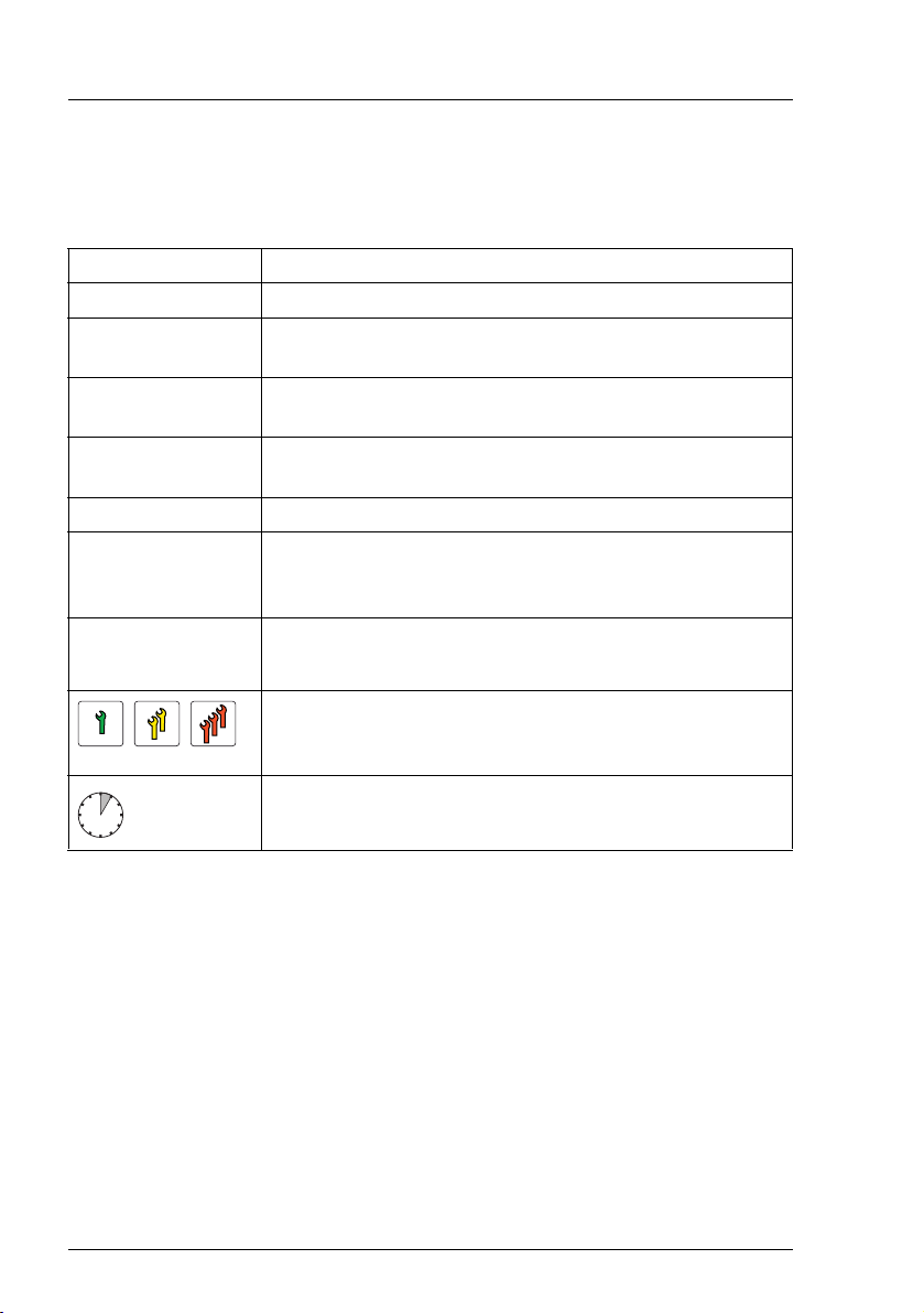
The following notational conventions are used in this manual:
Text in italics indicates commands or menu items
fixed font indicates system output
semi-bold fixed
font
"Quotation marks" indicate names of chapters and terms that are being
Ê describes activities that must be performed in the order
[Abc] indicates keys on the keyboard
V
CAUTION! Pay particular attention to texts marked with this symbol!
I
indicates text to be entered by the user
emphasized
shown
Failure to observe this warning may endanger your life,
destroy the system or lead to the loss of data.
indicates additional information, notes and tips
indicates the procedure category in terms of complexity
and qualification requirements, see "Classification of
procedures" on page 25
22 Upgrade and Maintenance Manual
indicates the average task duration, see "Average task
duration" on page 28
RX2530 M2
2 Before you start
Before you start any upgrade or maintenance task, please proceed as follows:
Ê Carefully read the safety instructions in chapter "Important information" on
page 33.
Ê Make sure that all necessary manuals are available. Refer to the
documentation overview in section "Documents you need at hand" on
page 31. Print the PDF files if required.
Ê Make yourself familiar with the procedure categories introduced in section
"Classification of procedures" on page 25.
Ê Ensure that all required tools are available according to section "Tools you
need at hand" on page 29.
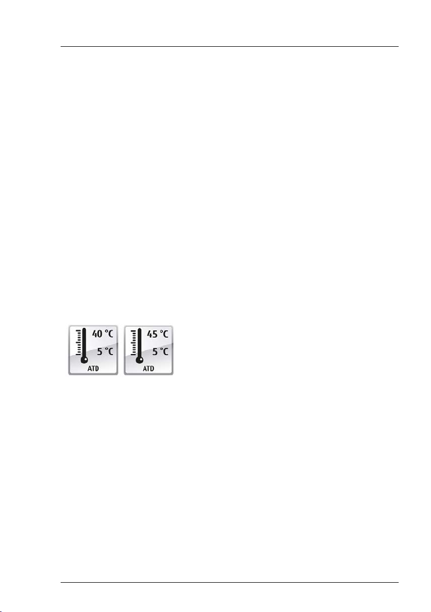
Advanced Thermal Design
The Advanced Thermal Design option allows you to operate the system with a
wider temperature range either of 5 °C to 40 °C or 5 °C to 45 °C, depending on
your system and configuration.
This option can only be ordered from the
manufacturer and is indicated by the respective
logo on the identification rating plate.
V
CAUTION
In a system that is configured with Advanced Thermal Design, only
certain components which support the respectively increased higher
operating temperature range may be installed and used. For applicable
restrictions, please refer to the official configurator tool.
Installing optional components
The operating manual of your server gives an introduction to server features
and provides an overview of available hardware options.
Use the Fujitsu ServerView Suite management software and the iRMC web
frontend to prepare hardware expansions. ServerView Suite documentation is
available online at http://manuals.ts.fujitsu.com
(http://jp.fujitsu.com/platform/server/primergy/manual/ for the Japanese market).
RX2530 M2
Upgrade and Maintenance Manual 23

Before you start
Please refer to the following ServerView Suite topics:
– Operation
– Virtualization
– Maintenance
– Out-Of-Band Management
I
For the latest information on hardware options, refer to your server’s
hardware configurator available online at the following address:
for the global market:
http://ts.fujitsu.com/products/standard_servers/index.htm
for the Japanese market:
http://jp.fujitsu.com/platform/server/primergy/system/
Please contact your local Fujitsu customer service partner for details on how to
order expansion kits or spare parts. Use the Fujitsu Illustrated Spares Catalog
to identify the required spare part and obtain technical data and order
information. Illustrated Spares catalogs are available online at
http://manuals.ts.fujitsu.com/illustrated_spares (global market only).
Replacing a defective component
The Global Error indicator on the front of the server reports defective hardware
components that need to be replaced. For further information on the controls
and indicators of your server, refer to the operating manual of your server and
section "Connectors and indicators" on page 356.
If the system has been powered off in order to replace a non-hot plug unit, a
system of PRIMERGY diagnostic indicators guides you to the defective
component. The "Indicate CSS" button enables the indicator next to the
defective component even if the server has been switched off and disconnected
from the mains. For further information, please refer to sections "Using
diagnostics information" on page 45 and "Indicators on the front panel" on
page 363.
If the defective component is a customer replaceable unit included in the CSS
concept (Customer Self Service), the CSS indicator on the front side of the
server will light up.
It is recommended to prepare local maintenance tasks using remote diagnostics
procedures, as described in the "ServerView Suite Local Service Concept
(LSC)" manual.
24 Upgrade and Maintenance Manual
RX2530 M2
Before you start
2.1 Classification of procedures
The complexity of maintenance procedures varies significantly. Procedures
have been assigned to one of three unit categories, indicating the level of
difficulty and required qualification.
At the beginning of each procedure, the involved unit type is indicated by one of
the symbols introduced in this section.
I
Please ask your local Fujitsu service center for more detailed
information.
2.1.1 Customer Replaceable Units (CRU)
Customer Replaceable Units (CRU)
Customer Replaceable Units are intended for customer self service and may be
installed or replaced as hot-plug components during operation.
I
Components that the customer is entitled to replace may differ according
to the service form in his country.
For the Japanese market use the following address:
http://jp.fujitsu.com/platform/server/primergy/
Hot-plug components increase system availability and guarantee a high degree
of data integrity and fail-safe performance. Procedures can be carried out
without shutting down the server or going offline.
Components that are handled as Customer Replaceable Units
– Hot-plug power supply units
– Hot-plug fan modules
– Hot-plug HDD/SSD modules
Peripherals that are handled as Customer Replaceable Units
– Keyboard
– Mouse
RX2530 M2
Upgrade and Maintenance Manual 25

Before you start
2.1.2 Upgrade and Repair Units (URU)
Upgrade and Repair Units (URU)
Upgrade and Repair Units are non hot-plug components that can be ordered
separately to be installed as options (Upgrade Units) or are available to the
customer through customer self service (Repair Units).
I
Server management error messages and diagnostic indicators on the
front panel and system board will report defective Upgrade and Repair
Units as customer replaceable CSS components.
Upgrade and repair procedures involve shutting down and opening the server.
V
CAUTION!
The device may be seriously damaged or cause damage if it is opened
without authorization or if repairs are attempted by unauthorized and
untrained personnel.
Components that are handled as Upgrade Units
– Processors (upgrade kits)
– Optical disk drives
– Expansion cards
– Flash backup units
– Memory modules
–SATA DOM
– iRMC microSD card
Components that are handled solely as Repair Units
– CMOS battery
26 Upgrade and Maintenance Manual
RX2530 M2

Before you start
2.1.3 Field Replaceable Units (FRU)
Field Replaceable Units (FRU)
Removing and installing Field Replaceable Units involves complex maintenance
procedures on integral server components. Procedures will require shutting
down, opening and disassembling the server.
V
CAUTION!
Maintenance procedures involving Field Replaceable Units must be
performed exclusively by Fujitsu service personnel or technicians trained
by Fujitsu. Please note that unauthorized interference with the system
will void the warranty and exempt the manufacturer from all liability.
Components that are handled as Field Replaceable Units
– Processor (replacement)
– SAS / SATA backplanes
– Front panel module
– System board
– Trusted Platform Module (TPM)
– USB Flash Module (UFM)
I
Please ask your local Fujitsu service center for more detailed
information.
RX2530 M2
Upgrade and Maintenance Manual 27
Before you start
2.2 Average task duration
Hardware: 10 minutes
The average task duration including preliminary and concluding steps is
indicated at the beginning of each procedure next to the procedure class.
Refer to the following table for an overview of steps taken into account for
calculating the average task duration:
Step included Explanation
Shutdown time depends on hardware and
software configuration and may vary
Server shutdown no
Rack removal,
disassembly
Transport no
Maintenance
procedures
Transport no
Assembly,
rack installation
Starting up no
Table 1: Calculation of the average task duration
yes
yes
yes
significantly.
Software tasks necessary before
maintenance are described in section
"Starting the maintenance task" on page 71.
making the server available, removing the
server from the rack (if applicable)
Transporting the server to the service table
(where required) depends on local
customer conditions.
maintenance procedures including
preliminary and concluding software tasks
Returning the server to its installation site
(where required) depends on local
customer conditions.
reassembling the server, installing the
server in the rack (if applicable)
Booting time depends on hardware and
software configuration and may vary
significantly.
28 Upgrade and Maintenance Manual
RX2530 M2
Before you start
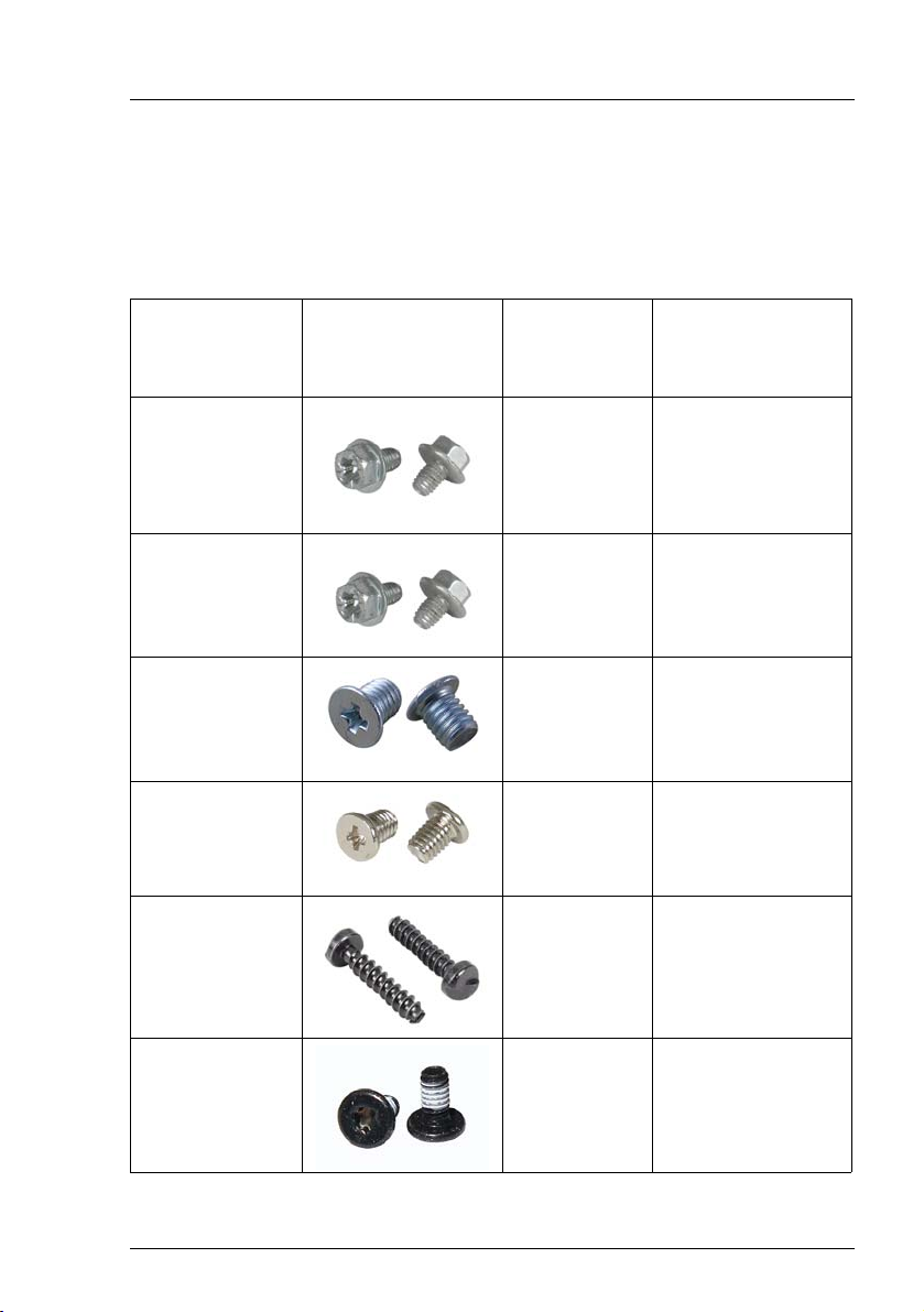
2.3 Tools you need at hand
When preparing the maintenance task, ensure that all required tools are
available according to the overview below. You will find a list of required tools at
the beginning of each procedure.
Screw driver /
Bit insert
Torque
Phillips
PH2 / (+) No. 2
0.6 Nm
Screw Usage Type
Slot bracket to
chassis,
system board,
SAS expander
board
M3 x 4.5 mm
(silver)
C26192-Y10-C67
Phillips
PH2 / (+) No. 2
0.6 Nm
Phillips
PH2 / (+) No. 1
0.6 Nm
Phillips
PH1 / (+) No. 1
0.4 Nm
Special bit insert
0.4 Nm
Torx Plus 6
0.2 Nm
Table 2: List of used screws (not applicable for the Japanese market)
Slot bracket to
expansion
card
3.5-inch HDD
Front VGA,
2.5-inch HDD,
DynamicLoM
module
TPM screw
ODD latch
M3 x 3.5 mm
(silver)
C26192-Y10-C151
UNC
6-32 x 5 mm
(black)
C26192-Y10-C200
M3 x 3.5 mm
(silver)
C26192-Y10-C102
REM 3 x 15 mm
(black)
C26192-Y10-C176
M2 x 4 mm
(black)
C26192-Y10-C166
RX2530 M2
Upgrade and Maintenance Manual 29
Before you start
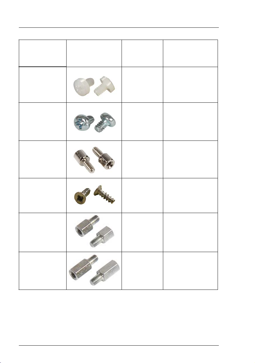
Screw driver /
Bit insert
Torque
Screw Usage Type
Phillips
PH1 / (+) No. 1
0.06 Nm
Phillips
PH1 / (+) No. 1
0.4 Nm
Hexagon bolt
0.6 Nm
Phillips
PH1 / (+) No. 1
0.4 Nm
SW5
0.6 Nm
UFM nylon
screw
TFM
Front VGA
connector,
serial interface
Front panel on
QRL
DynamicLoM
module
(D3245,
D3255)
M3 x 4.5 mm
(white)
A3C40109082
M2.5 x 4 mm
(silver)
A3C40137316
UNC #4-40
(silver)
V26827-B408-V989
M2.5 x 8 mm
(silver)
C26192-Y10-C174
M3 x 5 mm
(silver)
C26192-Y1-C65
SW5
0.6 Nm
Table 2: List of used screws (not applicable for the Japanese market)
30 Upgrade and Maintenance Manual
DynamicLoM
module
(D3265,
D3275)
M3 x 8 mm
(silver)
C26192-Y1-C66
RX2530 M2
Loading...