


Operator’s
Manual
 7000 Series ATB
Automatic Transfer &
Bypass–Isolation Switches
F–design, 3000 and 4000 amp. sizes
TABLE OF CONTENTS
section-page INSTALLATION . . . . . . . . . . . . . . . . . . . . . . . . 1-1 Mounting . . . . . . . . . . . . . . . . . . . . . . . . . . . . . 1-1 Power Connections . . . . . . . . . . . . . . . . . . . . 1-2 Engine Starting & Auxiliary Circuits . . . . . . 1-2 Functional Test . . . . . . . . . . . . . . . . 1-5, 1-6, 1–7
TESTING & SERVICE . . . . . . . . . . . . . . . . . . 2-1 Transfer Test . . . . . . . . . . . . . . . . . . . . . . . . . . 2-1 Preventive Maintenance . . . . . . . . . . . . . . . . 2-1 Disconnecting the Controller . . . . . . . . . . . . 2-1 Manual Load Transfer . . . . . . . . . . . . . . . . . . 2-2 Trouble-Shooting . . . . . . . . . . . . . . . . . . . . . . 2-2
BYPASSING & ISOLATING . . . . . . . . . . . . . . 3-1 Bypassing the ATS . . . . . . . . . . . . . . . . . . . . 3-1 Isolating the ATS . . . . . . . . . . . . . . . . . . . . . . 3-1 Return to Service . . . . . . . . . . . . . . . . . . . . . . 3-3
INDEX . . . . . . . . . . . . . . . . . . . . . . . . . back cover
An experienced licensed electrician must install ATB
Refer to the outline and wiring drawings provided with your 7000 Series ATB for all installation and connection details and accessories.
Refer to Group 5 Controller User’s Guide 381333–126 for ATS status display messages, time delays, pickup & dropout settings, and adjustments.
Rating Label
Each 7000 Series ATB contains a rating label to define the loads and fault circuit withstand/closing ratings. Refer to the label on the Transfer Switch for specific values.
!
Do not exceed the values on the rating label. Exceeding the rating can cause personal injury or serious equipment damage.
Nameplate
The Transfer Switch nameplate includes data for each specific 7000 Series ATB. Use the switch only within the limits shown on this nameplate. A typical Catalog Number is shown below with its elements explained:
Catalog Number Identification
Typical 7000 Series ATB catalog no. for overlapping neutral, 3 pole, 4000 amp, 480 V, in Type 1 enclosure:
7ATB C 3 4000 N 5 C
Neutral |
|
Phase Poles |
|
Amperes |
|
Voltage |
|
|
Controller |
|
Enclosure |
|
A – solid |
|
2 – single Ø |
|
3000 |
|
A 115 |
J 400 |
|
|
5 – standard |
|
C – type 1 |
C – overlapping |
|
3 – three Ø |
|
4000 |
|
B 120 |
K 415 |
|
|
5X – if accesso- |
|
F – type 3R |
blank --- none |
|
|
|
|
|
C 208 |
L 440 |
|
|
ries ordered |
|
G – type 4 |
|
|
|
|
|
|
|
|
|
||||
|
|
|
|
|
|
D 220 |
M 460 |
|
|
|
|
L – type 12 |
|
|
|
|
|
|
E 230 |
N 480 |
|
|
|
|
blank – open type |
|
|
|
|
|
|
F 240 |
P 550 |
|
|
|
|
|
|
|
|
|
|
|
|
|
|
|
|
||
|
|
|
|
|
|
G 277 |
Q 575 |
|
|
|
|
|
|
|
|
|
|
|
H 380 |
R 600 |
|
|
|
|
|
|
|
|
|
|
|
|
|
|
||||
|
50 Hanover Road, Florham Park, New Jersey 07932–1591 USA |
|
381333–133 A |
|||||||||
|
1 800 937–2726 (ASCO), for service call 1 800 800–2726 (ASCO) |
www.asco.com |
||||||||||
ASCO POWER TECHNOLOGIES CANADA PO Box 1238, 17 Airport Road, Brantford, Ontario, Canada N3T 5T3 telephone 519 758–8450, fax 519 758–0876, for service call 1 888 234–2726 (ASCO) www.asco.ca
SECTION 1 INSTALLATION
The ASCO 7000 Series Automatic Transfer & Bypass– Isolation Switch (ATB) consists of an upper bypass–isola- tion switch, a transfer switch, a monitoring and transfer controller, and door–mounted controls. The ATB is factory wired and tested. Installation requires removal of the shipping skid then securing the enclosure to the supporting foundation.
Remove the Transfer Switch
The Transfer Switch is shipped inside the enclosure (ATS side) in the fully engaged position. Before installing the enclosure remove the Transfer Switch as follows:
1.Open the enclosure doors and install the two ramps (stored on right side).
2.Remove the Isolation Handle which is stored on the lower right front of the Transfer Switch carriage frame. Install the Isolation Handle onto the protruding shaft and turn it counterclockwise (approximately 10 turns) until it stops.
3.Unplug J2 and J5 harness plugs, and roll out the Transfer Switch. Cover it to keep it clean.
Supporting Foundation
The supporting foundation and adjacent area must be level and straight, otherwise the Transfer Switch and enclosure may not align causing door problems. The floor under the enclosure must be flat and level. This is very important! The structure of the enclosure must be straight and square. Allow at least 36 inches for roll out of Transfer Switch. Refer to the enclosure drawing for required door opening space.
If bottom cable entry is used, the foundation must be prepared so that conduit stubs are located correctly. Refer to appropriate enclosure outline drawing for specified cable entrance area and location. Provide cable bending space and clearance to live metal parts. When a concrete floor is poured, use interlocking conduit spacer caps or a wood or metal template to maintain proper conduit alignment.
Mounting
Refer to the enclosure outline drawing furnished with this switch and mount the 7000 Series ATB according to the details and instructions shown on the drawing.
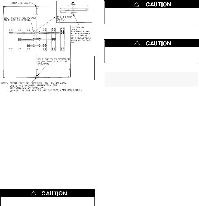
Bolt the cubicle sections together so that they are lined up on the front faces. See Figure 1–1.
De–energize the conductors before making any line or auxiliary circuitry connections. Be sure that Normal and Emergency line connections are in proper phase rotation. Place engine generator starting control in the OFF position. Make sure engine generator is not in operation.
Testing Power Conductors
Do not connect the power conductors to the ATB until they are tested. Installing power cables in conduit, cable troughs, and ceiling-suspended hangers often requires considerable force. The pulling of cables can damage insulation and stretch or break the conductor’s strands. For this reason, after the cables are pulled into position, and before they are connected they should be tested to verify that they are not defective or have been damaged during installation.
!
Protect the switch from construction grit and metal chips to prevent malfunction or shortened life for the ATB switch.
1--1
INSTALLATION (continued)
Connecting Power Conductors
A Wiring Diagram is furnished with the ATB. All wiring must be made in accordance with the local codes. After the power cables have been tested, connect them to the appropriate terminal lugs on the Bypass Switch as shown on the wiring diagram provided with this ATB. Make sure that the lugs provided are suitable for use with the cables being installed. Standard terminal lugs are solderless screw type and will accept the wire sizes listed on the drawings provided with the ATB. Be careful when stripping insulation from conductors; avoid nicking or ringing the conductor. Remove surface oxides from conductors by cleaning with a wire brush. Follow conductor manufacturer’s instructions when aluminum conductor is used. Apply joint compound to conductor, then carefully wipe away excess compound. Tighten the cable lugs to the torque specified on the rating label.
!
Be sure that the Normal and Emergency power connections are in proper phase rotation.
Figure 1–1. Bus tie plates (top view).
!
See job specific drawings supplied with ATB.
Bus Connections
If bus connection is used, use SAE grade 5 hardware to connect bus to appropriate terminal plates on bypass switching device. Wipe off bus surfaces before they are joined. If bus is dirty, gently clean surfaces with a non-flammable solvent. Avoid touching cleaned surfaces.
!
Do not breathe cleaning solvent vapors.
Use SAE grade 5 hardware and tighten the bolted joints to the torque specified in Table 2-1.
!
The reliability of the connection depends on how clean and how tight the joint is.
Table 2-1. Tightening torque values for bolted joints.
Bolt Diameter |
Recommended |
(Grade 5 hardware) |
Tightening Torque |
in inches |
in foot pounds |
5/16 |
12 |
3/8 |
20 |
1/2 |
50 |
5/8 |
95 |
3/4 |
155 |
Harnesses
All internal connections are made at the factory. The bypass switch, transfer switch, and control panel are joined together by an interconnecting wire harness. The disconnect plugs are already engaged on enclosed switches. For open–type switches, the plugs must be engaged after installation is completed. Align harness plugs with sockets in the control and push them together until they are secure.
Engine Starting Contacts
and Auxiliary Circuits
The engine control contact signal connections and auxiliary circuits are located on terminal block TB as shown on the Wiring Diagram provided with the ATB. Connect the signal wires to the appropriate terminals.
1--2

INSTALLATION (continued)
Install the Transfer Switch
After the enclosure is installed and power cables or bus connected to the Bypass Switch, the Transfer Switch carriage can be rolled in. The floor of the cabinet must be free of debris and clean. If necessary, use a vacuum cleaner. Make a thorough inspection to be sure no tools are left inside. The Bypass Handle must be in the BYPASS POS position (closed on normal). The Isolation Handle (drawout crank) must be fully counterclockwise against stop.
Do not apply any electrical power to the ATB yet.
It is not necessary to remove the barriers from the bypass switch and transfer switch. If you do remove them, however, reinstall them carefully.
NOTE: Be sure to roll the correct Transfer Switch into the enclosure. If more than one is supplied, each will be labeled above the solenoid operator.
The Transfer Switch NORMAL contacts must be closed. If not, use the manual operator handle (maintenance handle stored on lower carriage) to manually operate the switch. See Figure 1–10. Check that all arc chutes and interphase barriers are in place on the Transfer Switch. Then grasp the Transfer Switch carriage frame and roll it into the cabinet (isolation contacts facing inward). Align the rollers between the floor guides and push the carriage in until its crank pins engage the latch plates on both sides. Then follow the procedure below:
NOTE: Solenoid lock SL1 on the Isolation shaft inhibits operation of the drawout (Isolation contacts) unless the Transfer Switch and Bypass Switch are in compatible positions. This solenoid must energize to unlock. Because all power sources are de-energized, the interference tag defeats the solenoid in the following inspections.
Do the three inspections on page 1-4 without any electrical power connected. The inspections will verify that the isolation contacts are in proper alignment. If necessary, add shims under the floor. It may be helpful to remove the the right side of the enclosure to expose the isolation contacts during the inspections.
!
Do not apply any power to the Bypass Switch. Be sure that the Normal and Emergency source circuit breakers are OPEN before proceeding.
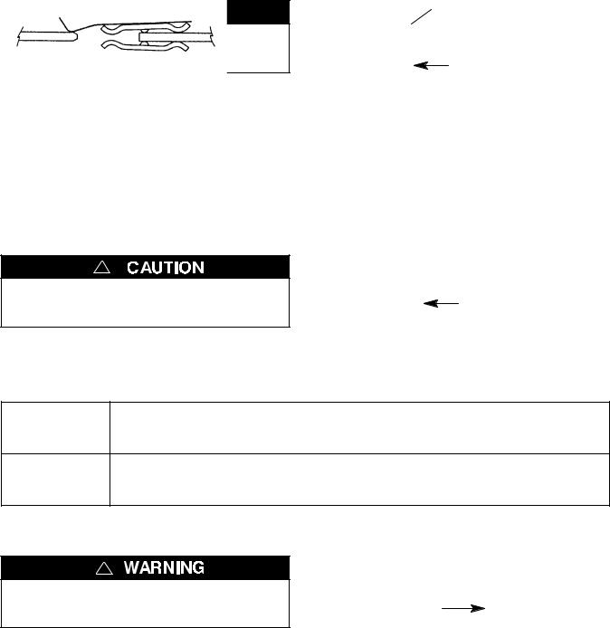
Remove interference tag after making inspection
on page 1-4. SL1 solenoid
lock
handle
carriage |
Isolation |
frame |
Handle shaft |
Figure1–2. Solenoid latch interference tag.
Turn the draw-out crank while checking alignment of the isolation contacts.
Figure 1–3. Isolation Handle.
Transfer Switch
NOMINAL CONTACT GAP 1/8” WHEN OPEN.
Figure 1–4. Switched neutral interlock.
1--3
INSTALLATION (continued)
Inspection 1
!
Do not force the Isolation Handle. Be sure that the sensing lead isolation contacts do not hit the male stabs head on, but rather slide on them.
TS
Figure 1–5. Isolation contacts in TEST position.
|
Move ATS from DISCONNECTED To TEST Position |
|
|
(without electrical power) |
|
|
|
|
Action |
Turn the Isolation Handle (Figure 1–3) clockwise approximately 7 or 8 turns. |
|
Observe |
The Transfer Switch should be pulled inward; the sensing lead isolation |
|
contacts should make with the male stabs as shown in Figure 1–5. |
||
|
||
|
Inspection 2 |
!
Do not force the Isolation Handle. Be sure that the isolation contact fingers make with the male stabs on both sides in the CONNECTED position.
IS 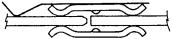 TS
TS
Figure 1–6. Isolation contacts CONNECTED (CLOSED).
Move ATS From TEST To CONNECTED Position
(without electrical power)
With solenoid latch interference tag in place (Figure 1–2), continue slowly Action turning the Isolation Handle clockwise until it stops (approximately 6 or 7
turns). Now remove the interference tag from the solenoid latch.
The Transfer Switch should be pulled inward; the isolation contact fingers Observe should make with the male stabs as shown in Figure 1–6. Also check that
the Bypass Switch switched neutral contacts have opened (Figure 1–4).
Inspection 3
!
Be sure that the isolation contacts disconnect in the TEST position; the sensing lead contacts should still touch the male stabs.
IS 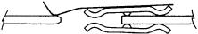 TS
TS
Figure 1–7. Isolation contacts back in TEST position.
|
Move ATS From CONNECTED Back To TEST Position |
|
|
(without electrical power) |
|
|
|
|
Action |
Turn the Isolation Handle (Figure 1–3) back counterclockwise until the |
|
isolation contacts separate (approximately 6 or 7 turns). |
||
|
||
|
The Transfer Switch should be pushed outward; the isolation contacts |
|
Observe |
should disconnect, but the sensing lead contacts should remain touching |
|
|
as shown in Figure 1–7. |
If all inspections are satisfactory connect harness plugs J2 and J5. Proceed to the Function Test.
1--4
 Loading...