


48HJ015-025
Installation Instructions
CONTENTS
Page
SAFETY CONSIDERATIONS ...................1
INSTALLATION .............................1-12
Step 1 — Provide Unit Support ...............1
• ROOF CURB
• ALTERNATE UNIT SUPPORT
Step 2 — Rig and Place Unit ..................3
• POSITIONING
• ROOF MOUNT
Step 3 — Field Fabricate Ductwork ............7
Step 4 — Make Unit Duct Connections ........7
Step 5 — Install Flue Hood ...................7
Step6—TrapCondensate Drain .............8
Step 7 — Install Gas Piping ...................8
Step 8 — Make Electrical Connections ........9
• FIELD POWER SUPPLY
• FIELD CONTROL WIRING
Step 9 — Make Outdoor-Air Inlet
Adjustments ...............................10
• MANUAL OUTDOOR-AIR DAMPER
• OPTIONAL FACTORY-INSTALLED
ECONOMIZER
Step 10 — Install Outdoor-Air Hood ..........10
START-UP ................................12-17
SERVICE ..................................18-27
START-UP CHECKLIST .....................CL-1
48HJ015-025
Single Package Rooftop Units
Electric Cooling/Gas Heating
1. Improper installation, adjustment, alteration, service, or maintenance can cause property damage, personal injury, or loss of life. Refer to the User’s Information Manual provided with this unit for more
details.
2. Do not store or use gasoline or other flammable vapors and liquids in the vicinity of this or any other
appliance.
What to do if you smell gas:
1. DO NOT try to light any appliance.
2. DO NOT touch any electrical switch, or use any phone
in your building.
3. IMMEDIATELY call your gas supplier from a neighbor’s phone. Follow the gas supplier’s instructions.
4. If you cannot reach your gas supplier, call the fire
department.
Disconnect gas piping from unit when pressure testing
at pressure greater than 0.5 psig. Pressures greater than
0.5 psig will cause gas valve damage resulting in haz-
ardous condition. If gas valve is subjected to pressure
greater than 0.5 psig, it must be replaced before use. When
pressure testing field-supplied gas piping at pressures of
0.5 psig or less, a unit connected to such piping must be
isolated by closing the manual gas valve(s).
SAFETY CONSIDERATIONS
Installation and servicing of air-conditioning equipment
can be hazardous due to system pressure and electrical components. Only trained andqualified service personnel should
install, repair, or service air-conditioning equipment.
Untrained personnel can perform the basic maintenance
functions of cleaning coils and filters and replacing filters.
All other operations should be performed by trained service
personnel. When working on air-conditioning equipment, observe precautions in the literature, tags and labels attached
to the unit, and other safety precautions that may apply.
Follow all safety codes.W earsafetyglasses and work gloves.
Use quenching cloth for unbrazing operations. Have fire extinguishers available for all brazing operations.
Before performing service or maintenance operations on
unit, turn offmain power switch to unit. Electrical shock
could cause personal injury.
Manufacturer reserves the right to discontinue, or change at any time, specifications or designs without notice and without incurring obligations.
Book 1
Tab 1a
PC 111 Catalog No. 534-807 Printed in U.S.A. Form 48HJ-9SI Pg 1 2-95 Replaces: 48HJ-5SI
Step 1 — Provide Unit Support
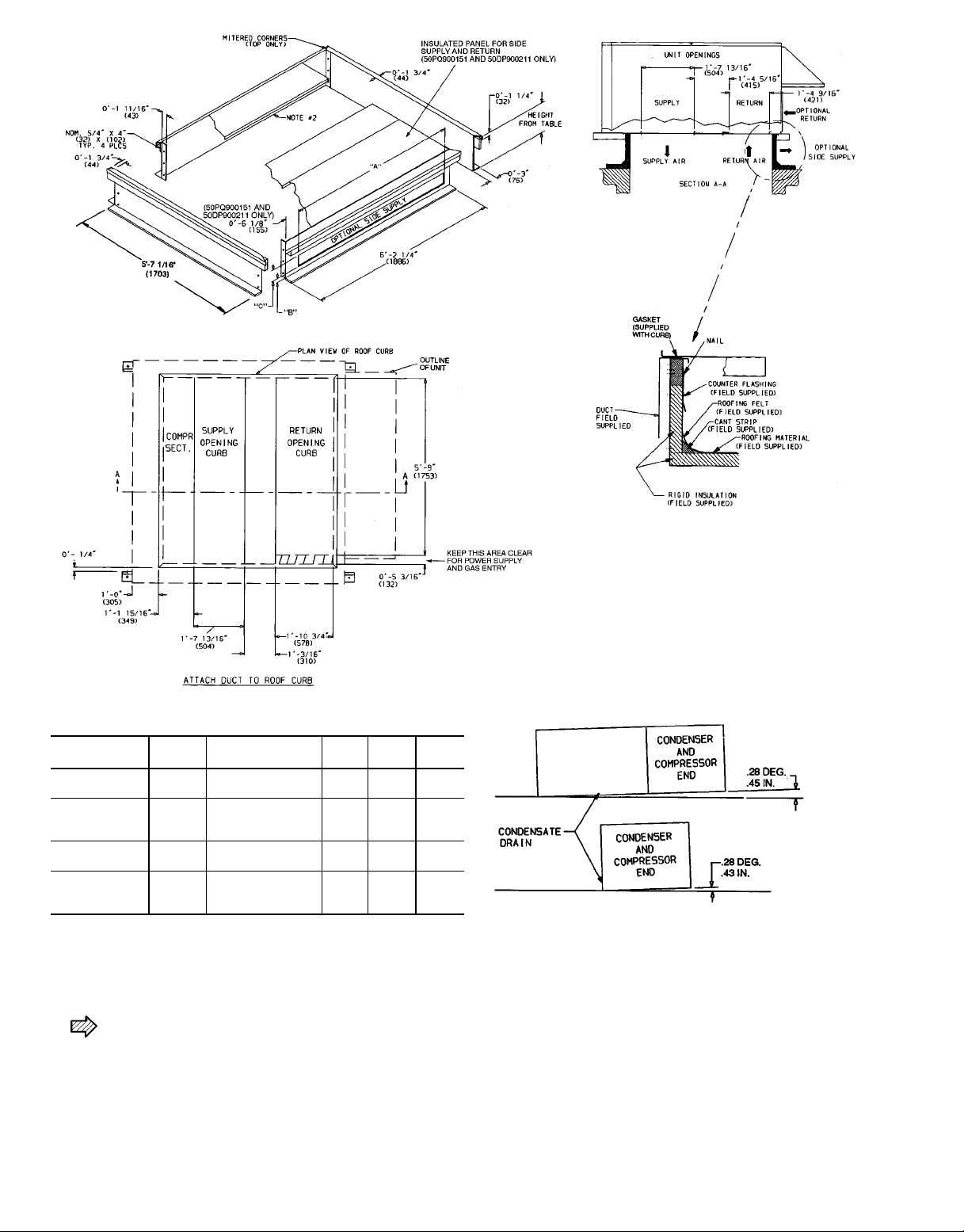
ROOF CURB — Assemble or install accessory roof curb in
accordance with instructions shipped with this accessory. See
Fig. 1 and 2. Install insulation, cant strips, roofing, and counter
flashing as shown. Ductwork can be installed to roof curb
before unit is set in place. Curb should be level. This is necessary to permit unit drain to function properly. Unit leveling tolerance is ±1⁄16in. per linear ft in any direction. Refer
to Accessory Roof Curb Installation Instructions for additional information as required. When accessory roof curb is
used, unit may be installed on class A, B, or C roof covering
material.
IMPORTANT: The gasketing of the unit to the roof
curb is critical for a watertight seal. Install gasket with
the roof curb as shown in Fig. 1. Improperly applied
gasket can also result in air leaks and poor unit
performance.
INSTALLATION
Instructions continued on page 3.
ACCESSORY
PACKAGE NO.
50PQ900221
50PQ900141
50PQ900151
50DP900211
CURB
HEIGHT
18-29
(305)
28-09
(610)
28-09
(610)
18-119
(584)
DESCRIPTION ‘‘A’’ ‘‘B’’ ‘‘C’’
Standard Curb —
149 High
Standard Curb
for Units Requiring
High Installation
Horizontal Supply
and Return Curb
Pre-Assembled,
High-Static,
Horizontal Adapter
LEGEND
COMP SECT. — Compressor Section
NOTES:
1. Roof curb accessory is shipped unassembled.
2. Insulated panels,
3. Dimensions in ( ) are in millimeters.
1
⁄2-in. thick neoprene-coated, 2 lb density.
4. Direction of airflow.
5. Roof curb: 18 gage steel.
6. Attach all ductwork to roof curb.
7. Field installation of sidewall is mandatory.
Fig. 1 — Roof Curb and Horizontal Adapter Details
———
———
08-2
(64)
08-6
(159)
1
⁄
2
9
18-69
(457)
1
⁄
4
9
18-25⁄
(371)
58-69
(1676)
68-29
(1880)
8
9
NOTE: To prevent the hazard of stagnant water build-up in the drain
pan of the indoor-air section, unit can only be pitched as shown.
2
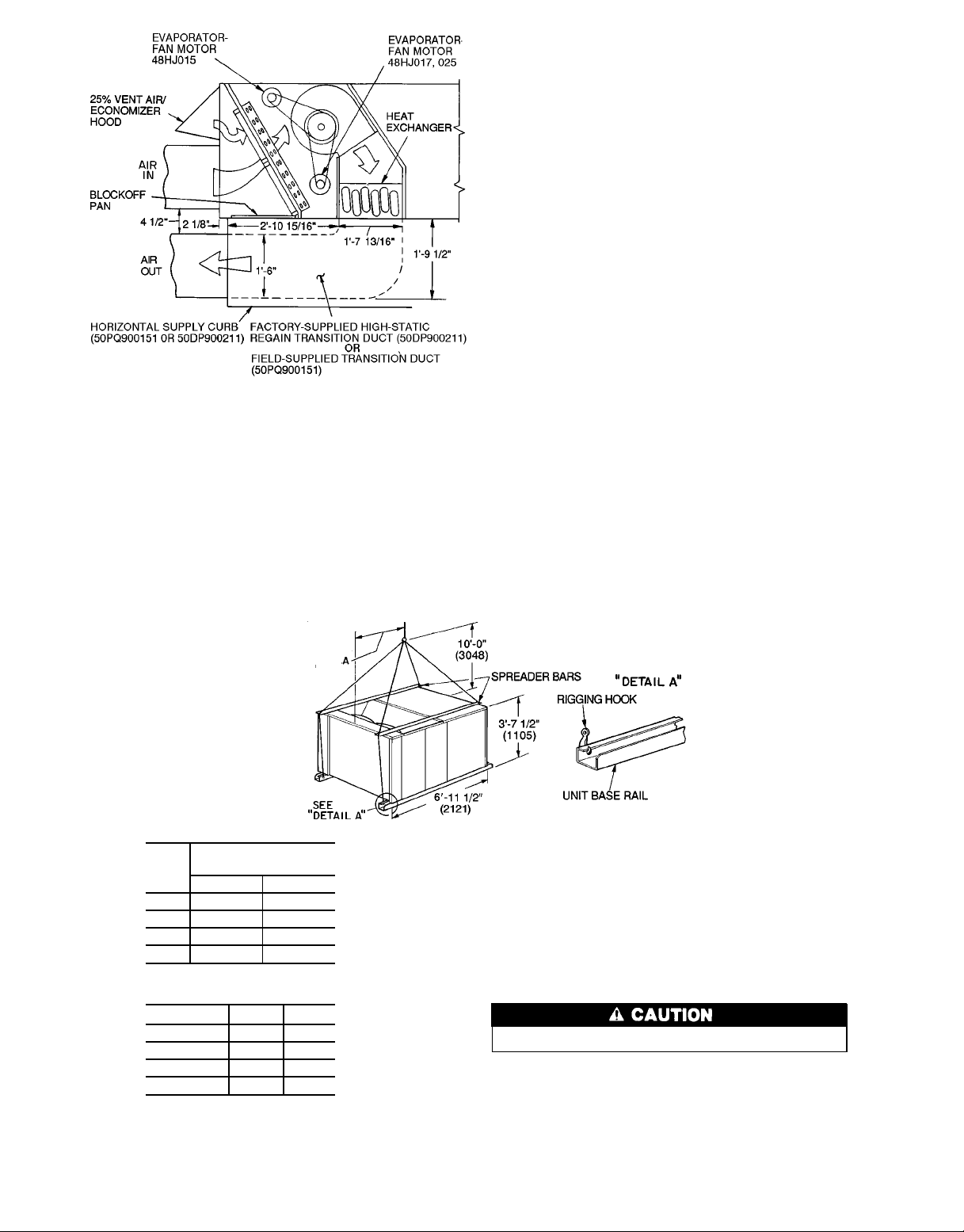
Fig. 2 — Horizontal Supply/Return Curb
and Horizontal Adapter Details
ALTERNATE UNIT SUPPORT — When the curb cannot
be used, install unit on a noncombustible surface. Support
unit with sleepers, using unit curb support area. If sleepers
cannot be used, support long sides of unit with a minimum
of 3 equally spaced 4-in. x 4-in. pads on each side.
Step2 — Rig and Place Unit — Inspect unit for trans-
portation damage. File any claim with transportation agency.
Do not drop unit; keep upright. Use spreader bars over
unit to prevent sling or cable damage. Rollers may be used
to move unit across a roof. Level by using unit frame as a
reference; leveling tolerance is ±
1
⁄16in. per linear ft in any
direction. See Fig. 3 for additional information. Unit operating weight is shown in Table 1.
Four lifting holes are provided in ends of unit base rails
as shown in Fig. 3. Refer to rigging instructions on unit.
POSITIONING — Maintain clearance, per Fig. 4 and 5, around
and above unit to provide minimum distance from combustible materials, proper airflow, and service access.
Do not install unit in an indoor location. Do not locate
unit air inlets near exhaust vents or other sources of contaminated air. For proper unit operation, adequate combustion and ventilation air must be provided in accordance with
Section 5.3 (Air for Combustion and Ventilation) of the
National Fuel Gas Code, ANSI Z223.1 (American National
Standards Institute).
Although unit is weatherproof, guard against water from
higher level runoff and overhangs.
Locate mechanical draft system flue assembly at least
4 ft from any opening through which combustion products
could enter the building, and at least 4 ft from any adjacent
building. When unit is located adjacent to public walkways,
flue assembly must be at least 7 ft above grade.
ROOF MOUNT — Check building codes for weight distribution requirements. Unit weight is shown in Table 1.
Instructions continued on page 7.
MAXIMUM SHIPPING
UNIT
48HJ
D015 1920 871
E015 1940 880
E017 2310 1048
D025 2535 1150
WEIGHT
Lb Kg
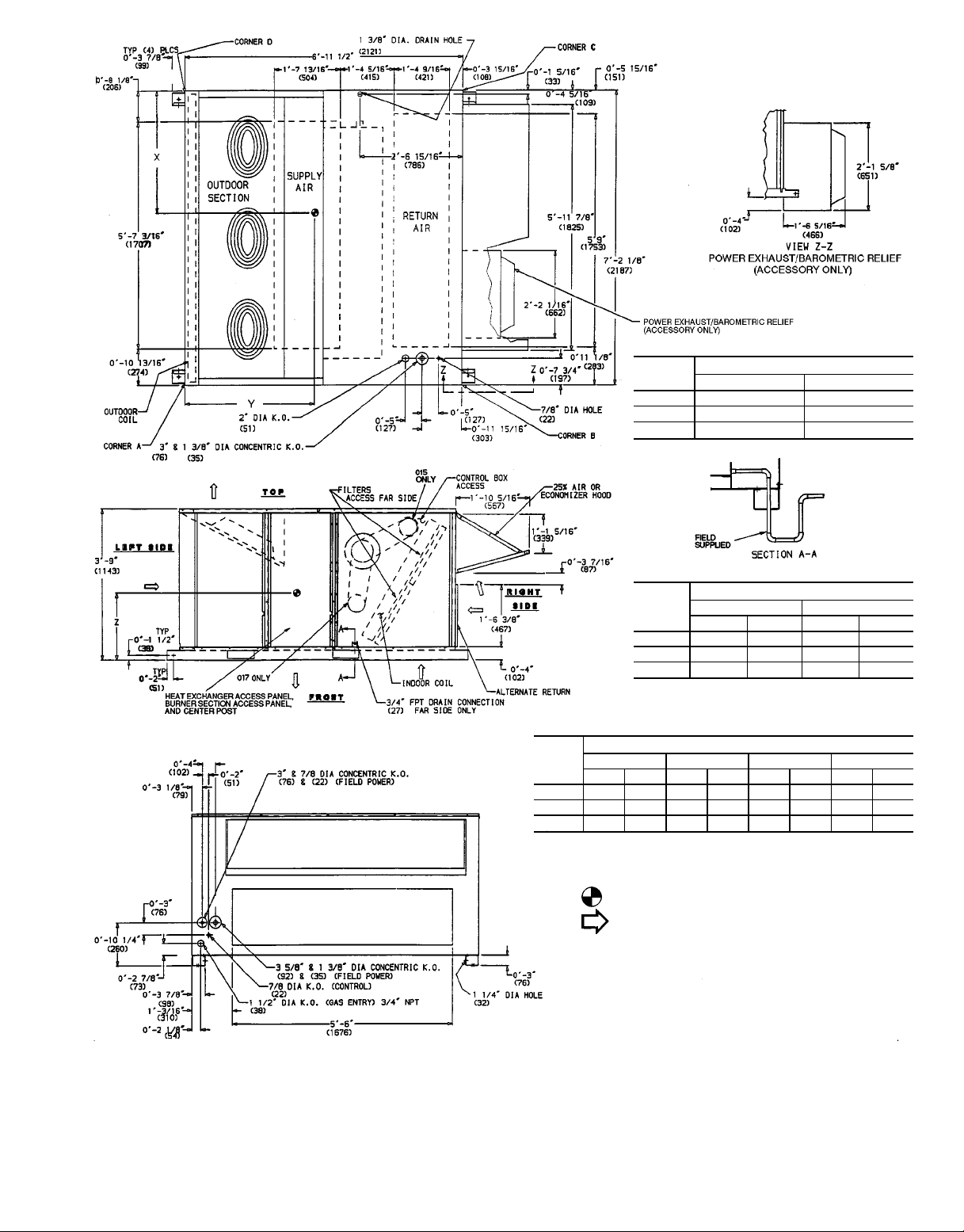
Dimension A
UNIT Ft-in. mm
48HJD015 3-1
48HJE015 3-1
48HJE017 3-4
48HJD025 3-4
3
⁄
8
1
⁄
4
3
⁄41035
3
⁄41010
949
946
NOTES:
1. Dimensions in ( ) are in millimeters.
2. Refer to Table 1 for unit operating weights.
3. Remove boards at ends of unit and runners prior to rigging.
4. Rig by inserting hooks into unit base rails as shown. Use corner
postfrompackaging to protect coil fromdamage.Usebumper boards
for spreader bars.
5. Weights do not include optional economizer.See Table1 for economizer weight.
6. Weights given are for aluminum evaporator coil plate fins and copper condenser coil plate fins. Weights of other metal combinations
are listed in Table 1.
All panels must be in place when rigging.
Fig. 3 — Rigging Details
3
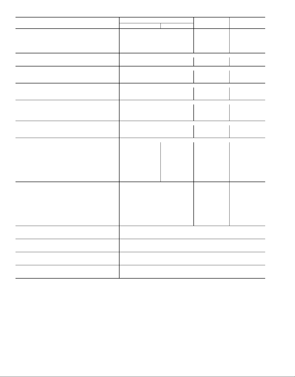
Table 1 — Physical Data
UNIT SIZE 48
OPERATING WT (lb)
COMPRESSOR 06D Semi-Hermetic
REFRIGERANT TYPE R-22
CONDENSER COIL Copper Tubes, Aluminum or Copper Plate Fins
CONDENSER FAN Propeller Type, Direct Drive
EVAPORATOR COIL Copper Tubes, Aluminum or Copper Plate Fins
EVAPORATOR FAN Centrifugal, Adjustable Pitch Belt Drive
FURNACE SECTION
HIGH-PRESSURE SWITCH
LOW-PRESSURE SWITCH
Al/Al* 1640/1660 2010 2235
Unit Al/Cu* 1770/1790 2160 2385
Cu/Cu* 1840/1860 2250 2515
Economizer 110 110 110
Roof Curb† 200 200 200
Number 122
Cylinders 646
Charge (lb)
System 1 22.50 14.25 17.50
System 2 — 15.00 17.00
Rows 344
Fins/in. 15 15 15
Total Face Area (sq ft) 22.2 22.2 22.2
Nominal Cfm 10,500 10,500 14,200
Number...Diameter (in.) 3...22 3...22 2...30
Motor Hp (1075 Rpm)
Watts Input (Total) 1090 1090 3400
Rows 234
Fins/in. 17 15 15
Total Face Area (sq ft) 17.9 17.9 17.9
Quantity...Size (in.) 2...10 x 10 2...10 x 10 2...12 x 12 2...12 x12
Nominal Cfm 5000 5000 6000 8000
Fan Rpm Range 1194-1526 1201-1462 1238-1494 1323-1579
Maximum Allowable Rpm 1550 1550 1550 1550
Motor Pulley Pitch Diameter (in.) 3.4/4.4 4.3/5.3 5.4/6.6 5.8/7.0
Fan Pulley Pitch Diameter (in.) 5.2 6.4 7.9 7.9
Belt, Quantity...Type...Length (in.) 1...AX...42 1...B...45 1...BX...50 1...BX...51
Factory Speed Setting (Rpm) 1293 1279 1366 1451
Motor Hp (Service Factor) 3.7 (1.15) 3 (1.15) 5 (1.15) 10 (1.15)
Motor Frame Size 56H 56H 184T 215T
Rollout Switch Cutout Temp (F)** 190 190 190
Burner Orifice Diameter (in. ...drill size)
Natural Gas
Pilot Orifice Diameter (Quantity) in. ...drill size
Natural Gas
Thermostat Heat Anticipator Setting
Stage 1
Stage 2
Gas Valve Quantity 1/2 2 2
Cutout (psig) 426
Reset (psig) 320
Cutout (psig) 7
Reset (psig) 22
208/230, 460 V 575 V
AIR INLET SCREENS Cleanable
Economizer, Quantity...Size (in.)
RETURN-AIR FILTERS (TYPE) 10% Efficient — 2-in. Throwaway Fiberglass
Quantity... Size (in.)
HJD015/HJE015
1
⁄
2
HJE017 HJD025
1
⁄
2
.113...33 .113...33 .113...33
(1) .055...54/
(1) .055...54
(1) .041...59
1.2/1.2
—/0.6
2...20 x 25 x 1
1...20 x 20 x 1
4...20 x 20 x 2
4...16 x 20 x 2
(1) .055...54
(1) .041...59
1.2
0.6
1...1075
(1) .055...54
(1) .041...59
1.2
0.6
LEGEND
Al — Aluminum
Cu — Copper
*Evaporator coil fin material/condenser coil fin material.
†Weight of 14 in. roof curb.
**Rollout switch is manual reset.
4
UNIT
48HJ
MAXIMUM SHIPPING WEIGHT
Lb Kg
D015 1920 871
E015 1940 880
E017 2310 1048
UNIT
48HJ
Ft-in. mm Ft-in. mm
DIMENSIONS
XY
D015 3-2 965 4-0 1219
UNIT
48HJ
E015 3-2 965 4-0 1219
E017 3-7
ABCD
Lb Kg Lb Kg Lb Kg Lb Kg
3
⁄
8
1102 3-65⁄
WEIGHT OF CORNER*
8
D015 365 166 360 163 373 169 540 245
E015 372 169 363 165 377 171 547 248
E017 509 231 506 230 475 216 519 235
*Weights are for unit only and do not include options or crating.
NOTES:
1. Dimensions in ( ) are in millimeters.
2. Center of gravity.
3. Direction of airflow.
4. Ductwork to be attached to accessory roof curb only.
5. Minimum clearance:
a. Rear: 78-09 (2134)for coil removal. This dimension can bereduced
to 48-09 (1219) if conditions permit coil removal from the top.
b. Left side: 48-09 (1219) for proper condenser coil airflow.
c. Front: 48-09 (1219) for control box access.
d. Right side: 48-09 (1219) for proper operation of damper and power
exhaust (if so equipped).
e. Top: 68-09 (1829) to assure proper condenser fan operation.
f. Local codes or jurisdiction may prevail.
6. Withtheexception of clearance forthe condenser coil andthe damper/
power exhaust as stated in Note No. 5, a removable fence or barricade requires no clearance.
7. Dimensions are from outside of corner post. Allow 08side for top cover drip edge.
5
⁄169 (8) on each
1083
Fig. 4 — Base Unit Dimensions, 48HJ015,017
5
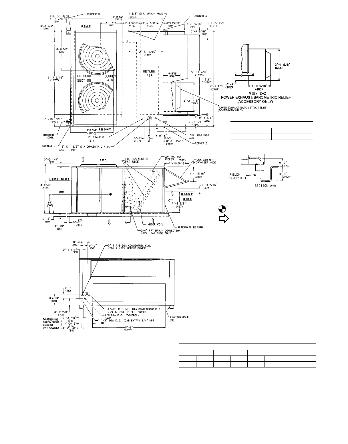
MAXIMUM SHIPPING WEIGHT
Lb Kg
2535 1150
NOTES:
1. Dimensions in ( ) are in millimeters.
2. Center of gravity.
3. Direction of airflow.
4. Ductwork tobe attached to accessoryroofcurb only.
5. Minimum clearance:
a. Rear: 7809 (2134) for coil removal. This dimen-
sion can be reduced to 4809 (1219) if conditions
permit coil removal from the top.
b. 4809 (1219) to combustible surfaces, allfour sides
(includes between units).
c. Left side: 4809 (1219) for proper condenser coil
airflow.
d. Front: 4809 (1219) for control box access.
e. Right side: 4809 (1219) for proper operation of
damper and power exhaust (if so equipped).
f. Top: 6809 (1829) to assure proper condenser fan
operation.
g. Bottom: 149 (356)tocombustible surfaces (when
not using curb).
h. Control box side: 3809 (914) to ungrounded sur-
faces (non-combustible).
i. Controlboxside: 3869 (1067) to block or concrete
walls, or other grounded surfaces.
j. Local codes or jurisdiction may prevail.
6. With the exception of clearance for the condenser
coilandthe damper/power exhaust asstated in Note
No. 5, a removable fence or barricade requires no
clearance.
7. Dimensions are from outside of corner post. Allow
5
⁄169 (8) on each side for top cover drip edge.
08-
ABCD
Lb Kg Lb Kg Lb Kg Lb Kg
523 237 541 245 574 260 596 270
*Weights are for unit only and do not include options or crating.
Fig. 5 — Base Unit Dimensions, 48HJ025
6
CORNER WEIGHT*

Step 3 — Field Fabricate Ductwork — Secure all
ducts to building structure. Use flexible duct connectors between unit and ducts as required. Insulate and weatherproof
all external ductwork, joints, and roof openings with counter
flashing and mastic in accordance with applicable codes.
Ducts passing through an unconditioned space must be
insulated and covered with a vapor barrier.
Step 4 — Make Unit Duct Connections — Unit
is shipped for through-the-bottom duct connections. Ductwork openings are shown in Fig. 1, 4, and 5. Duct connections are shown in Fig. 6. Field-fabricated concentric ductwork may be connected as shown in Fig. 7 and 8. Attach all
ductwork to roof curb and roof curb basepans.
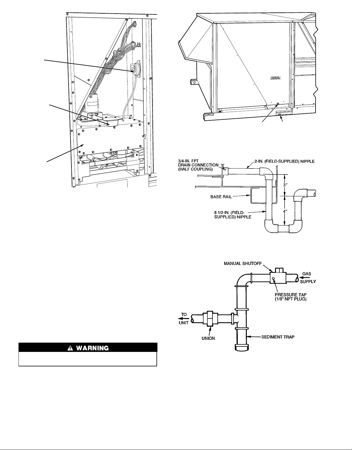
Step 5 — Install Flue Hood — Flue hood is shipped
secured to a baffle under main control box. To install, secure
flue hood to access panel. See Fig. 9.
NOTE: When properly installed, flue hood will line up with
combustion fan housing. See Fig. 10.
NOTE: Dimensions A, A8, B, and B8 are obtained from field-supplied
ceiling diffuser.
areas indicate block-off pans.
Fig. 8 — Concentric Duct Details
NOTE: Do not drill in this area; damage to basepan may result in
water leak.
Fig. 6 — Air Distribution — Through-the-Bottom
(48HJ017 and 025 Shown)
NOTE: Do not drill in this area; damage to basepan may result in
water leak.
Fig. 7 — Concentric Duct Air Distribution
(48HJ017 and 025 Shown)
Fig. 9 — Flue Hood Location
7
PRESSURE
SWITCH
COMBUSTION
FAN HOUSING
HEAT
EXCHANGER
SECTION
Fig. 10 — Combustion Fan Housing Location
Step6—TrapCondensate Drain — See Fig. 11
for drain location. One3⁄4-in. half coupling is provided
inside unit evaporator section for condensate drain connection. An 81⁄2in. x3⁄4-in. diameter and 2-in. x3⁄4-in. diameter
pipe nipple, coupled to standard3⁄4-in. diameter elbows, provides a straight path down through hole in unit base rail (see
Fig. 12). A trap at least 4-in. deep must be used.
Step 7 — Install Gas Piping — Unit is equipped for
use with natural gas. Installation must conform with local
building codes or, in the absence of local codes, with the
National Fuel Gas Code, ANSI Z223.1.
Install manual gas shutoff valve with a
sure tap for test gage connection at unit. Field gas piping
must include sediment trap and union. See Fig. 13.
1
⁄8-in. NPT pres-
3/4" FPT DRAIN
CONNECTION
1-3/8"
DRAIN HOLE
Fig. 11 — Condensate Drain Details
Fig. 12 — Condensate Drain Piping Details
Do not pressure test gas supply while connected to unit.
Always disconnect union before servicing.
Natural gas pressure at unit gas connection must not be
less than 5 in. wg or greater than 13.5 in. wg.
Size gas-supply piping for 0.5-in. wg maximum pressure
drop. Do not use supply pipe smaller than unit gas connec-
3
tion (
⁄4-in. NPT).
Fig. 13 — Field Gas Piping
8
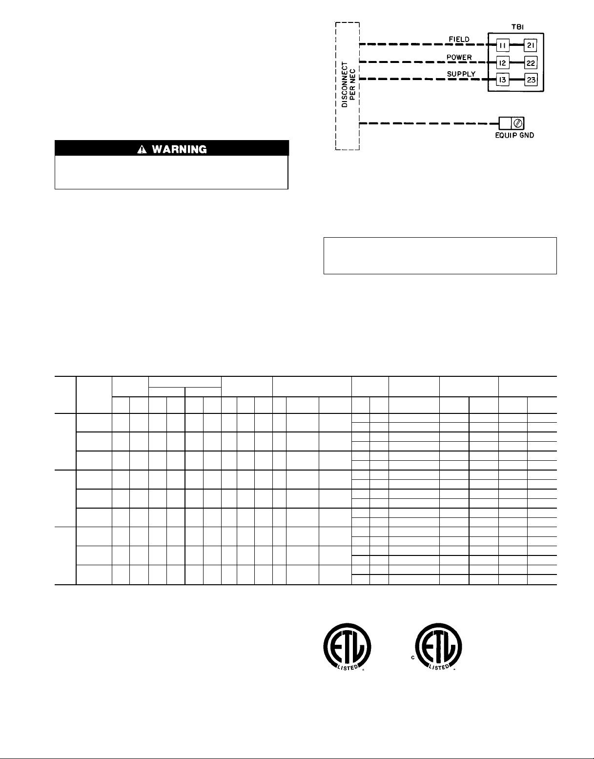
Step 8 — Make Electrical Connections
FIELD POWER SUPPLY — Unit is factory wired for voltage shown on unit nameplate.
When installing units, provide a disconnect per NEC
(National Electrical Code) of adequate size (Table 2).
All field wiring must comply with NEC and local
requirements.
Route power and ground lines through control box end
panel or unit basepan (see Fig. 4 and 5) to connections as
shown on unit wiring diagram and Fig. 14.
The unit must be electrically grounded in accordance
with local codes and NEC ANSI/NFPA 70 (National Fire
Protection Association).
Field wiring must conform to temperature limitations for
type ‘‘T’’wire. All field wiring must comply with NEC and
local requirements.
Transformer no. 1 is wired for 230-v unit. If 208/230-v
unit is to be run with 208-v power supply, the transformer
must be rewired as follows:
1. Remove cap from red (208 v) wire.
2. Remove cap from orange (230 v) spliced wire.
3. Replace orange wire with red wire.
4. Recap both wires.
Table 2 — Electrical Data
NOMINAL
UNIT
VOLTAGE
48HJ
(3 Ph,
60 Hz)
208/230 187 254 39.7 228 — — 3 1.7 3.8 3.7 10.5/10.5 84.5/84.5
015
208/230 187 254 28.2 160 28.2 160 3 1.7 24.8 5 15.8/15.8 105/91
017
208/230 187 254 35.6 198 35.6 198 2 5.5 24.8 10 28.0/28.0 193/168
025
FLA — Full Load Amps
HACR — Heating, Air Conditioning and Refrigeration
IFM — Indoor (Evaporator) Fan Motor
LRA — Locked Rotor Amps
MCA — Minimum Circuit Amps
MOCP — Maximum Overcurrent Protection
NEC — National Electrical Code
OFM — Outdoor (Condenser) Fan Motor
RLA — Rated Load Amps
*This is the maximum size permissible; smaller fuse size may be used where
conditions permit.
VOLTAGE
RANGE
Min Max RLA LRA RLA LRA Qty
460 414 508 19.9 114 — — 3 0.8 1.9 3.7 4.8 42.3
575 518 632 16.0 91 — — 3 0.75 1.5 3 3.9 23.4
460 414 508 14.1 80 14.1 80 3 0.8 10.8 5 7.9 46
575 518 632 11.3 64 11.3 64 3 0.75 8.4 5 6.0 37
460 414 508 17.8 99 17.8 99 2 2.8 10.8 10 14.6 84
575 518 632 14.3 79 14.3 79 2 3.4 8.4 10 13.0 66
LEGEND
COMPRESSOR
No. 1 No. 2
OFM IFM
FLA
LRA
(ea)
Hp FLA LRA FLA LRA FLA MCA MOCP* FLA LRA
(ea)
LEGEND
EQUIP — Equipment
GND — Ground
NEC — National Electrical Code
TB — Terminal Board
NOTE: Maximum wire size for TB1 is 2/0.
Fig. 14 — Field Power Wiring Connections
IMPORTANT: BE CERTAIN UNUSED WIRES
ARE CAPPED. Failure to do so may damage the
transformers.
Operating voltage to compressor must be within voltage
range indicated on unit nameplate. On 3-phase units, voltages between phases must be balanced within 2%.
POWER
EXHAUST
— — 0.57 65/65 100/100 64/64 324/324
4.6 18.8 0.57 70/70 100/100 70/70 343/343
— — 0.30 32 50 32 162
2.3 6.0 0.30 34 50 34 168
— — 0.57 26 40 26 119
2.1 4.8 0.57 28 40 29 124
— — 0.57 84/84 110/100 90/90 499/485
4.6 18.8 0.57 89/89 110/110 95/95 518/504
— — 0.30 42 50 45 238
2.3 6.0 0.30 44 50 47 244
— — 0.57 34 40 36 190
2.1 4.8 0.57 36 45 39 195
— — 0.57 119/119 150/150 127/127 639/614
4.6 18.8 0.57 124/124 150/150 133/133 657/632
— — 0.30 60 70 65 304
2.3 6.0 0.30 63 80 67 310
— — 0.57 52 60 56 241
2.1 4.8 0.57 54 60 59 246
NOTES: In compliance with NEC requirements for multimotor and combination load equipment (refer to NEC Articles 430 and 440), the overcurrent protective device for the unit shall be fuse or HACR breaker. The Canadian units
may be fuse or circuit breaker.
COMBUSTION
FAN MOTOR
POWER SUPPLY
DISCONNECT
SIZE
9
Use the following formula to determine the percent volt-
age imbalance.
% Voltage Imbalance:
= 100 x
max voltage deviation from average voltage
average voltage
EXAMPLE: Supply voltage is 460-3-60.
AB =452 v
BC =464 v
AC =455 v
Average Voltage =
452 +464 +455
1371
=
3
3
= 457
Determine maximum deviation from average voltage:
(AB) 457 −452 =5 v
(BC) 464 −457 =7 v
(AC) 457 −455 =2 v
Maximum deviation is 7 v.
Determine percent voltage imbalance:
% Voltage Imbalance =100 x
7
457
=1.53%
This amount of phase imbalance is satisfactory as it is below the maximum allowable 2%.
IMPORTANT: If the supply voltage phase imbalance
is more than 2%, contact your local electric utility company immediately.
Unit failure as a result of operation on improper line
voltage or excessive phase imbalance constitutes abuse and
may cause damage to electrical components.
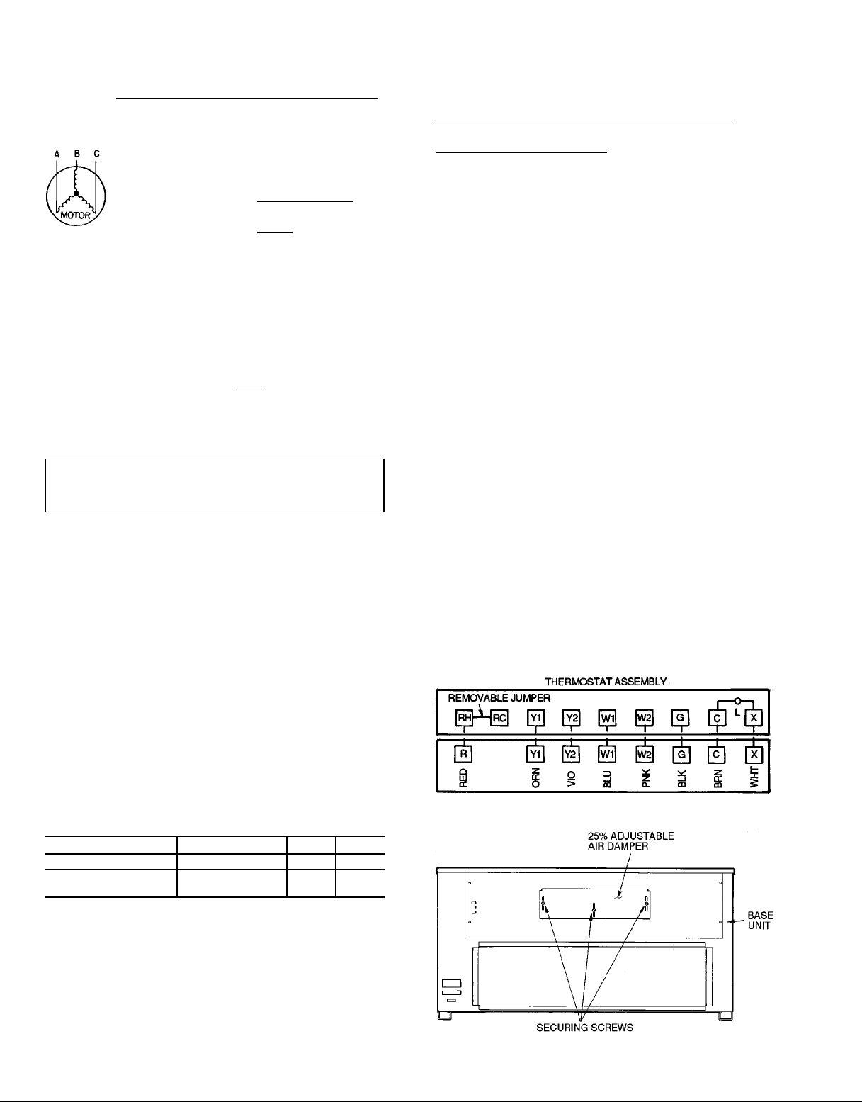
FIELD CONTROL WIRING — Install a Carrier-approved
accessory thermostat assembly according to installation
instructions included with accessory. Locate thermostat assembly on a solid interior wall in the conditioned space to
sense average temperature.
Route thermostat cable or equivalent single leads of colored wire from subbase terminals through conduit in unit to
low-voltage connections as shown on unit label wiring diagram and in Fig. 15.
NOTE: For wire runs up to 50 ft, use no. 18 AWG (American Wire Gage) insulated wire (35 C minimum). For 50 to
75 ft, use no. 16 AWG insulated wire (35 C minimum). For
over 75 ft, use no. 14 AWG insulated wire (35 C minimum).
All wire larger than no. 18 AWG cannot be directly connected at the thermostat and will require a junction box and
splice at the thermostat.
Set heat anticipator settings as follows:
Damper can be preset to admit up to 25% outdoor air into
return-air compartment. To adjust, loosen securing screws
and move damper to desired setting, then retighten screws to
secure damper (Fig. 16).
OPTIONAL FACTORY-INSTALLED ECONOMIZER
Economizer Motor Control Module (See Fig. 17-19) — Set
economizer motor to the D setting (Fig. 18).
Damper Vent Position Setting
1. Set fan switch at ON position (continuous fan operation)
and close night switch if used.
2. Set system selector switch at OFF position.
3. Turn damper adjustment knob located on control module
clockwise slowly until dampers assume desired vent position. Do not manually operate economizer motor. Dam-
age to motor will result.
NOTE: Refer to accessory installation instructions included
with the field-installed economizer for installation information.Also see Accessory Field-Installed Economizer Adjustment section on page 12.
Step10 — Install Outdoor-Air Hood— The outdoor-
air hood is common to 25% air ventilation and economizer.
If economizer is used, all electrical connections have been
made and adjusted at the factory.Assemble and install hood
in the field.
NOTE: The hood top cover, upper and lower filter retainers, hood drain pan, baffle (017 and 025 only), and filter support bracket are secured opposite the condenser end of the
unit. The screens, hood side panels, remaining section of filter support bracket, seal strip, and hardware are in a package
located inside the return-air filter access panel (Fig. 20).
1. Attach seal strip to upper filter retainer. See Fig. 21.
2. Assemble hood top cover, side panels, upper filter re-
tainer, and drain pan (see Fig. 22).
3. Secure lower filter retainer and long portion of support
bracket to unit. See Fig. 22. Leave screws loose on 017
and 025 units.
4. 48HJ017,025 Units Only: Slide baffle behind lower filter
retainer and tighten screws.
Fig. 15 — Field Control Thermostat Wiring
UNIT VOLTAGE UNIT W1 W2
48HJD015 All 1.20 —
48HJD025, HJE015,
HJE017
All 1.20 0.60
Settings may be changed slightly to provide a greater de-
gree of comfort for a particular installation.
Refer to Accessory Remote Control Panel instructions if
required.
Step 9 — Make Outdoor-Air Inlet Adjustments
MANUAL OUTDOOR-AIR DAMPER — All units (except
those equipped with a factory-installed economizer) have a
manual outdoor-air damper to provide ventilation air.
Fig. 16 — 25% Outdoor-Air Section Details
10
 Loading...