


GM9

USER’S INFORMATION,
MAINTENANCE AND
SERVICE MANUAL
HIGH EFFICIENCY
TUBULAR HEAT EXCHANGER SERIES
MODELS: GF9/GM9/GY9
(Single Stage Downflow/Horizontal)
EFFICIENCY
RATING
CERTIFIED
ISO 9001
Certified Quality
Management System
TABLE OF CONTENTS
CONTACT INFORMATION . . . . . . . . . . . . . . . . . . . . . . . . . . . . . . . .1
USER’S INFORMATION . . . . . . . . . . . . . . . . . . . . . . . . . . . . . . . . . . . 1
SAFETY . . . . . . . . . . . . . . . . . . . . . . . . . . . . . . . . . . . . . . . . . . . . . .1
INSTRUCTIONS FOR EXAMINING THE FURNACE
INSTALLATION . . . . . . . . . . . . . . . . . . . . . . . . . . . . . . . . . . . . . . . . .2
HOW YOUR GAS FURNACE WORKS . . . . . . . . . . . . . . . . . . . . . .3
START-UP AND SHUTDOWN INSTRUCTIONS . . . . . . . . . . . . . . .3
Read the Instructions Below Before Trying to Start the Furnace . .3
Operating Instructions: . . . . . . . . . . . . . . . . . . . . . . . . . . . . . . . . . .3
To Turn Off the Appliance: . . . . . . . . . . . . . . . . . . . . . . . . . . . . . . .3
FURNACE USER MAINTENANCE . . . . . . . . . . . . . . . . . . . . . . . . . .4
Blower Care . . . . . . . . . . . . . . . . . . . . . . . . . . . . . . . . . . . . . . . . . .4
Air Filters . . . . . . . . . . . . . . . . . . . . . . . . . . . . . . . . . . . . . . . . . . . .4
Removing Filters . . . . . . . . . . . . . . . . . . . . . . . . . . . . . . . . . . . . . .4
Motor Lubrication . . . . . . . . . . . . . . . . . . . . . . . . . . . . . . . . . . . . . .5
SERVICE AND MAINTENANCE MANUAL . . . . . . . . . . . . . . . . . . . . .5
SAFETY SECTION . . . . . . . . . . . . . . . . . . . . . . . . . . . . . . . . . . . . . .5
FURNACE MAINTENANCE SECTION . . . . . . . . . . . . . . . . . . . . . . .5
SEQUENCE OF OPERATION . . . . . . . . . . . . . . . . . . . . . . . . . . . . .5
Continuous Blower . . . . . . . . . . . . . . . . . . . . . . . . . . . . . . . . . . . . .5
Intermittent Blower - Cooling . . . . . . . . . . . . . . . . . . . . . . . . . . . . .5
Heating Cycle . . . . . . . . . . . . . . . . . . . . . . . . . . . . . . . . . . . . . . . . .5
Hot Surface Ignition System . . . . . . . . . . . . . . . . . . . . . . . . . . . . . .6
FURNACE CLEANING SECTION . . . . . . . . . . . . . . . . . . . . . . . . . . .6
Burner Removal/Cleaning . . . . . . . . . . . . . . . . . . . . . . . . . . . . . . .6
Cleaning the Heat Exchanger . . . . . . . . . . . . . . . . . . . . . . . . . . . .6
Cleaning the Secondary Heat Exchanger . . . . . . . . . . . . . . . . . . .6
Cleaning the Vent / Air Intake System . . . . . . . . . . . . . . . . . . . . . .6
TROUBLESHOOTING . . . . . . . . . . . . . . . . . . . . . . . . . . . . . . . . . . .6
FURNACE CONTROL DIAGNOSTICS . . . . . . . . . . . . . . . . . . . . . . .6
DIAGNOSTIC FAULT CODE STORAGE AND RETRIEVAL . . . . . .7
REPLACEMENT PARTS LIST . . . . . . . . . . . . . . . . . . . . . . . . . . . . . .8
REPLACEMENT PART CONTACT INFORMATION . . . . . . . . . . . . .10
WIRING DIAGRAM . . . . . . . . . . . . . . . . . . . . . . . . . . . . . . . . . . . . . .11
LIMITED WARRANTY . . . . . . . . . . . . . . . . . . . . . . . . . . . . . . . . . . . .12
CONTACT INFORMATION
• Go to website at www.york.com click on “contact”, then click on “contact form” and follow the instructions.
• Contact us by mail:
York International
Consumer Relations
5005 York Drive
Norman, OK 73069
The manufacturer recommends that the user read all sections of this manual and keep the manual for future reference.
FIRE OR EXPLOSION HAZARD - Failure to follow safety
warnings exactly could result in serious injury, death, or property damage.
— Do not store or use gasoline or other flammable vapors
and liquids in the vicinity of this or any other appliance.
— WHAT TO DO IF YOU SMELL GAS:
• Do not try to light any appliance.
• Do not touch any electrical switch; do not use any phone
(including cell phone) in your building.
• Leave the building immediately.
• Immediately call your gas supplier from a neighbor’s
phone. Follow the gas supplier’s instructions.
• If you cannot reach your gas supplier, call the fire department.
— Installation and service must be performed by a quali-
fied installer, service agency or the gas supplier.
SECTION I: USER’S INFORMATION
SAFETY
1. The furnace area must be kept clear and free of combustible materials, gasoline and other flammable vapors and liquids.
2. Insulating materials may be combustible. The furnace must be
kept free and clear of insulating materials. The furnace area must
be examined when installed in an attic or other insulated space or
when insulation is added to be sure that the insulation material has
been kept away from the furnace.
3. The furnace needs air for combustion in order to operate properly
and safely. Do not block or obstruct air openings on the furnace,
air openings to the area where the furnace is installed, or spaces
around the furnace.
4. Follow the instructions exactly as shown on the OPERATING
INSTRUCTION LABEL or the Start-up and Shutdown Instructions
on Page 3 of this manual when lighting the furnace or turning the
furnace off.
5. Should the gas supply fail to shut off or if overheating occurs, shut
off the gas valve to the furnace before shutting off the electrical
supply.
6. Do not use this furnace if any part has been under water. A flooddamaged furnace is extremely dangerous. Attempts to use the furnace can result in fire or explosion. A qualified service agency
should be contacted to inspect the furnace and replace all gas
controls, control system parts, electrical parts that have been wet
or the furnace if deemed necessary.
168106-PUM-A-1205
168106-PUM-A-1205
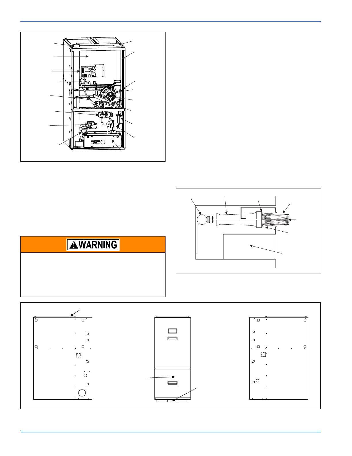
COMBUSTION
AIR PIPE
BLOWER
ACCESS
PANEL
CONTROL
BOARD
TRANSFORMER
PRESSURE
SWITCH
TUBING
PRESSURE
SWITCHES
GAS
VALV E
GAS
REFERENCE
HOSE
BURNER BOX
FIGURE 1: Component Locations
7. NEVER . . .Store flammable materials of any kind near your furnace. Gasoline, solvents, and other volatile liquids should be
stored only in approved containers outside your home. These
materials vaporize easily and are extremely dangerous.
8. NEVER . . .Store cleaning materials near your furnace. Materials
such as bleaches, detergents, powdered cleansers, etc., can
cause corrosion of the heat exchangers.
9. NEVER . . . Use the area around your furnace as a storage area
for items which could block the normal flow of air. This flow of air is
required for ventilation of the various furnace components.
VENT PIPE
CONDENSATE
HOSE
RAIN
GUTTER
INDUCER
HOUSING
INDUCER
MOTOR
CONDENSATE
DRAIN HOSE
CONDENSATE
TRAP
LIMIT
SWITCH
INSTRUCTIONS FOR EXAMINING THE FURNACE
INSTALLATION
It is the owner’s responsibility to ensure that an annual inspection of the
entire heating portion of the unit is made by a qualified service agency.
1. Examine the heat exchanger, through a field installed access
panel located on the supply air plenum. Visually examine the exterior sections of the vent/combustion air piping and the vent connectors to be sure that they are physically sound without holes or
excessive corrosion.
2. Examine the vent pipe making sure it is firmly in place, that it
slopes slightly upward and is physically sound without holes and
all of the connections are secure.
3. Examine the return-air duct connections to make sure they are
physically sound, sealed to the furnace casing, and the ducts terminate outside the space containing the furnace.
4. Examine the furnace casing making sure the physical support is
sound without sagging, cracks or gaps. Examine the furnace base
making sure it is physically sound without cracks, gaps or sagging
and has a good seal.
5. Examine the furnace casing for obvious signs of deterioration.
6. Examine the burner flames to make sure they are in good adjustment. Refer to the pictorial sketch shown in Figure 2 as a comparison to the actual flame.
7. Examine the furnace as outlined above in steps 1 - 6 before each
heating season. Use Figure 3 for visual reference.
MANIFOLD
MAIN BURNER
END OF
BURNER
BURNER
FLAME
YELLOW
TIPS
INNER FLAME
CONES
(Blue Flame)
FIRE OR EXPLOSION HAZARD
This furnace is designed and approved for use with Nat-
ural Gas and (LP) Propane Gas ONLY. DO NOT BURN
ANY LIQUID FUEL OR SOLID FUEL IN THIS FURNACE.
Burning any unapproved fuel will result in damage to the
furnace heat exchanger, which could result in Fire, Personal Injury, and/or Property Damage.
3
EXAMINE RETURN AIR
DUCT CONNECTION
4
EXAMINE
FURNACE
CASING
5
EXAMINE CASING
FOR DETERIORATION
6
REMOVE THIS
PANEL TO
EXAMINE THE
BURNER FLAMES
FIGURE 3: Furnace Examination Checkpoints
FIGURE 2: Burner Flame Drawing
BLOWER DOOR
2
REMOVE
THIS PANEL
TO EXAMINE
VENT PIPE
BURNER DOOR
1
PLACE A FIELD
INSTALLED ACCESS
PANEL LOCATED IN
THE DOWNFLOW
PLENUM TO EXAMINE
THE HEAT EXCHANGER
COMBUSTION AIR
TRANSITION
(not shown)
4
EXAMINE
FURNACE
CASING
5
EXAMINE CASING
FOR DETERIORATION
2 Unitary Products Group
168106-PUM-A-1205
HOW YOUR GAS FURNACE WORKS
Your furnace is a very easy appliance to take for granted. Season after
season, it sits there in your home, keeping you warm and comfortable.
For this reason, you may never have given much thought to the way
your furnace operates. In order to get the safest and most efficient operation from your furnace, you should understand how your furnace does
its job.
When you set your thermostat to provide more heat in your home, you
are starting the heating cycle of the furnace. First, the inducer motor
starts to purge the heat exchanger of any remaining gases. Next, the
hot surface igniter glows and after a warm-up period the gas valve
opens and ignition occurs. A short time later, the blower starts and distributes the warm air throughout the home. When the temperature setting on your thermostat is reached, the gas valve closes, the main
burners are turned off, and the blower continues to run until the remaining warm air in the system is distributed. When the blower stops, the
heating cycle has ended.
START-UP AND SHUTDOWN INSTRUCTIONS
Read the Instructions Below Before Trying to Start the
Furnace
If you do not follow these instructions exactly, a fire or
explosion may result causing property damage, personal
injury, and/or loss of life.
A. This appliance does not have a pilot. It is equipped with an ignition
device which automatically lights the burner. Do not try to light the
burner by hand.
B. BEFORE OPERATING; smell all around the appliance area for
gas. Be sure to smell next to the floor because some gas is
heavier than air and will settle on the floor.
C. Use only your hand to push the gas control switch to the “on” posi-
tion. Never use tools. If the switch will not operate by hand, don’t
try to repair it, call a qualified service technician. Force or
attempted repair may result in a fire or explosion.
D. Do not use this appliance if any part has been under water. Imme-
diately call a qualified service technician to inspect the appliance
and to replace any part of the control system and any gas control,
which has been under water.
Operating Instructions:
1. STOP! Read the safety information above.
2. Set the thermostat to the lowest setting.
3. Turn off all electric power to the appliance.
4. Remove burner door.
5. Move gas control switch to the “OFF” position. Do not force. See
Figure 4.
6. Wait five (5) minutes to clear out any gas. If you then smell gas,
STOP! Follow “B” in the safety information above. If you don’t
smell gas, go to next step.
7. Move gas control switch to the “ON” position. Do not force. See
Figure 4.
8. Replace burner door.
9. Turn on all electric power to the appliance.
10. Set thermostat to the desired setting. Burner will light, which may
take 30-60 seconds.
11. After three (3) trials for ignition, if the appliance will not operate follow the instructions, “TO TURN OFF THE APPLIANCE” and call
your service technician or gas supplier.
To Turn Off the Appliance:
1. Set the thermostat to lowest setting.
2. Turn off all electric power to the appliance if service is to be performed.
3. Remove burner access panel.
4. Move gas control switch to the “OFF” position. See Figure 4.
5. Replace burner access panel.
Should overheating occur, or the gas valve fail to shut off,
turn the external manual gas valve in the gas supply line to
the furnace to the “off” position and let the furnace cool off
before shutting off the electrical power supply. Refer to
Figures 5 & 6.
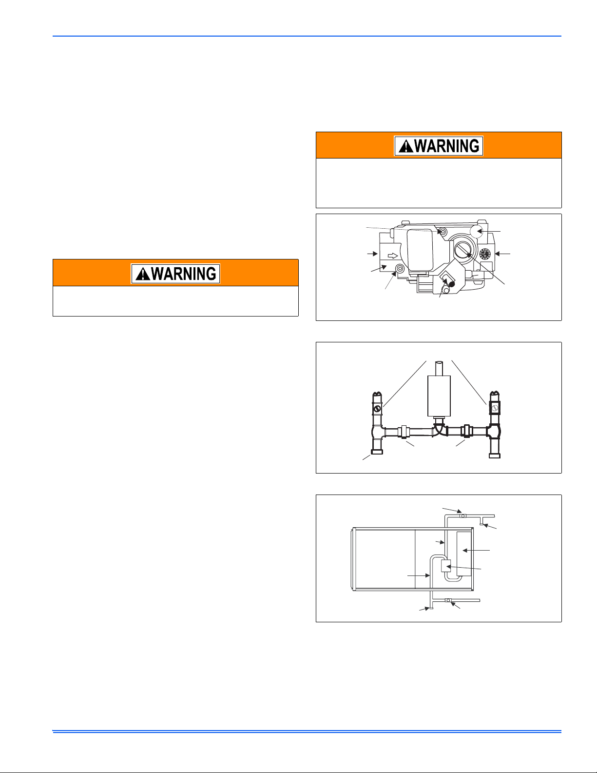
OUTLET
PRESSURE
PORT
INLET
WRENCH
BOSS
INLET
PRESSURE
PORT
ON/OFF SWITCH
(Shown in ON position)
OFF
ON
FIGURE 4: Gas Valve - White Rodgers
EXTERNAL MANUAL
SHUTOFF VALVE
TO GAS
SUPPLY
GROUNDED JOINT UNION
DRIP
LEG
MAY BE INSTALLED
INSIDE OR OUTSIDE UNIT.
FIGURE 5: Downflow Gas Piping
MANUAL
SHUT-OFF
VALV E
GAS
PIPE
GAS
PIPE
DRIP
LEG
MANUAL
SHUT-OFF VALVE
FIGURE 6: Horizontal Gas Piping
NOTE: The spring-loaded safety cut-off switch, mounted on the blower
deck, behind the indoor fan access panel will automatically cut
off the electrical power supply to the furnace when the blower
panel is removed. As a safety precaution, all electrical power
and the gas supply to the furnace should be turned off before
servicing.
VENT PORT
OUTLET
MAIN REGULATOR
ADJUSTMENT
TO GAS
SUPPLY
DRIP
LEG
GAS BURNERS
GAS VALVE
Unitary Products Group 3
168106-PUM-A-1205
FURNACE USER MAINTENANCE
Before proceeding, be sure the area is well ventilated. Turn
the thermostat OFF. If the blower is running, wait until it
stops automatically. Turn OFF the gas and electrical power
supplies to the furnace. Check all metal parts and surfaces
to be sure they have cooled to room temperature before
you begin.
Blower Care
Even with good filters properly in place, blower wheels and motors will
become dust laden after long months of operation. The entire blower
assembly should be inspected annually. If the motor and wheel are
heavily coated with dust, they can be brushed and cleaned with a vacuum cleaner. If the blower cannot be properly cleaned without removing
it from the furnace, then this service must be performed by a qualified
service agency.
The blower can be serviced/removed through the blower access panel
on the inside of the furnace. If there is a combustion air pipe installed
inside the furnace, it may have to be removed to access the blower
access panel. After the combustion air pipe is removed, it is easy to
remove the inside blower access panel by removing the screws of the
access panel. Blower is now ready to be serviced through the opening.
If the blower has to be removed through the inside blower access panel,
then the top and bottom angles will have to be removed to slide the
blower out of the furnace.
Make sure you DO NOT move the clip-on weight on the
indoor fan wheel when cleaning the wheel. This weight is
used to balance the wheel. Moving the weight will cause
the fan wheel to vibrate.
Air Filters
The filters should be checked every 3 months. On new construction,
check the filters every week for the first four weeks and every three
weeks after that, especially if the indoor fan is running continuously.
When replacing the filter(s), refer to Table 1 to be sure you install the
right size filter for your furnace. Dirty filters greatly restrict the flow of air
and may cause damage to the moving parts of the furnace. If the filters
become clogged the heat exchangers and blower motor could overheat
resulting in a potentially dangerous situation.
Never operate your furnace without a suitable air filter.
Use the following procedure to determine the filter size.
1. Measure the furnace width and use that measurement to determine the cabinet width.
• A 14-1/2” wide cabinet is a “A” cabinet.
• A 17-1/2” wide cabinet is a “B” cabinet.
• A 21” wide cabinet is a “C” cabinet.
• A 24-1/2” wide cabinet is a “D” cabinet.
2. After you determine the cabinet size and what return configuration
you have, look up the recommended filter size from Table 1.
Removing Filters
Some downflow furnaces have their filters located on the top of the furnace in an external filter rack. To check filters you should:
1. Follow the instructions to turn off the appliance before servicing.
2. Filters are installed in the return air plenum above the blower
assembly. An “A” frame assembly supports the filters. Lift the filter
slightly and remove for service.
3. Follow the instructions “HOW TO CLEAN YOUR FURNACE’S FILTER”.
4. Reverse the procedure to reinstall filters.
5. Follow the operating instructions to place appliance in operation.
Externally Mounted Air Filters
Some installations may have the air filter in a rack attached to the casing of the furnace or placed in the return air duct. You can gain access
to the filter by pulling on the door or unscrewing the retaining screw,
then slide the filter(s) out of its channel. Replace throw away filter(s)
with the same size new filter(s). Throw away filter(s) may be replaced
with cleanable filter(s) at this time. Cleanable filter(s) may be cleaned as
described in the manufacturer instructions or as described below and
then re-installed.
How to Clean your Filter
High-velocity filters may be cleaned with a vacuum cleaner or washed
with a garden hose. Be sure to shake off excess water and allow filter to
completely dry before re-installing the filter.
To replace the filter after cleaning you must do the following:
1. Slide filter into place.
2. Snap the door on or place the door in position and tighten the
retaining screws, if provided.
3. Make sure the door is secure to the end of the filter rack.
4. For filter grilles, place the filter into the grilles, close the grille cover
and tighten the retaining screw.
Every time the filters are changed the following items should be visually
inspected:
• Check combustion air and vent pipe for blockage or leakage.
• Check all components to be sure they are in good condition and
that there are no obvious signs of deterioration.
• Check the drain lines to make sure there are no cracks or leaks.
• Check for dirt or lint on any surfaces or on components. Do not try
to clean any of the surfaces or components. Cleaning of the furnace and its components must be done by a qualified service professional.
If, during the inspection of your furnace, you find any of the following
conditions:
• Excessive amounts of dust and lint on components.
• Damaged or deteriorated components or surfaces.
• Leaks or blockage in the vent pipe passages.
• Water on any surface inside or outside of the furnace.
Do not operate the furnace, call a certified dealer / servicing contractor
to check and / or clean your furnace, or for more information if you have
questions about the operation of your furnace.
If all components appear to be in good operating condition, replace the
front panels. Turn ON the gas and electrical power supplies to the furnace, and set thermostat to the desired temperature.
4 Unitary Products Group
 Loading...