


OWNER’S MANUAL
YP125E
YP180E
5XL-F819D-E3


INTRODUCTION
EAU10110
Welcome to the Yamaha world of motorcycling!
As the owner of the YP125E/YP180E, you are benefiting from Yamaha’s vast experience and newest technology regarding the design and manufacture of high-quality products, which have earned Yamaha a reputation for dependability. Please take the time to read this manual thoroughly, so as to enjoy all advantages of your YP125E/YP180E. The owner’s manual does not only instruct you in how to operate, inspect and maintain your scooter, but also in how to safeguard yourself and others from trouble and injury.
In addition, the many tips given in this manual will help keep your scooter in the best possible condition. If you have any further questions, do not hesitate to contact your Yamaha dealer.
The Yamaha team wishes you many safe and pleasant rides. So, remember to put safety first!
IMPORTANT MANUAL INFORMATION
|
|
|
|
|
EAU34110 |
Particularly important information is distinguished in this manual by the following notations: |
|||||
|
|
|
|
|
|
|
t |
|
The Safety Alert Symbol means ATTENTION! BECOME ALERT! YOUR SAFETY IS |
||
|
|
|
|
|
INVOLVED! |
|
|
|
|
|
|
|
|
|
|
|
|
|
|
|
|
|
|
|
|
|
|
||
|
s WARNING |
|
Failure to follow WARNING instructions could result in severe injury or death to the |
||
|
|
|
|
|
scooter operator, a bystander, or a person inspecting or repairing the scooter. |
|
|
|
|
|
|
|
|
|
|
|
|
|
CAUTION |
|
|
A CAUTION indicates special precautions that must be taken to avoid damage to |
|
|
|
|
|
|
the scooter. |
|
|
|
|
|
|
|
|
|
|
|
|
|
NOTE: |
A NOTE provides key information to make procedures easier or clearer. |
|||
|
|
|
|
|
|
NOTE:
●This manual should be considered a permanent part of this scooter and should remain with it even if the scooter is subsequently sold.
●Yamaha continually seeks advancements in product design and quality. Therefore, while this manual contains the most current product information available at the time of printing, there may be minor discrepancies between your scooter and this manual. If you have any questions concerning this manual, please consult your Yamaha dealer.
EWA12410
s WARNING
PLEASE READ THIS MANUAL CAREFULLY AND COMPLETELY BEFORE OPERATING THIS SCOOTER.
IMPORTANT MANUAL INFORMATION
EAUS1171
YP125/YP180
OWNER’S MANUAL
©2005 by YAMAHA MOTOR ESPAÑA S.A. 1st edition, September 2005
All rights reserved.
Any reprinting or unauthorized use without the written permission of YAMAHA MOTOR ESPAÑA S.A. is expressly prohibited.
Printed in Spain.

TABLE OF CONTENTS
SAFETY INFORMATION ..................... |
1-1 |
DESCRIPTION..................................... |
2-1 |
Left view ........................................... |
2-1 |
Right view ......................................... |
2-2 |
Controls and Instruments ................. |
2-3 |
INSTRUMENT AND CONTROL |
|
FUNCTION .......................................... |
3-1 |
Main switch....................................... |
3-1 |
Indicator lights .................................. |
3-1 |
Speedometer unit ............................. |
3-3 |
Battery voltage/fuel gauge ............... |
3-3 |
Clock................................................. |
3-4 |
Handlebar switches .......................... |
3-4 |
Front brake lever............................... |
3-5 |
Rear brake lever................................ |
3-6 |
Fuel tank cap .................................... |
3-6 |
Fuel ................................................... |
3-6 |
Seat................................................... |
3-7 |
Front storage compartment.............. |
3-7 |
Storage compartment....................... |
3-7 |
Adjusting the rear shock absorber |
|
assemblies..................................... |
3-8 |
Sidestand.......................................... |
3-8 |
Sidestand switch operation check ... |
3-9 |
PRE-OPERATION CHECKS ............... |
4-1 |
Pre-operation check list.................... |
4-2 |
OPERATION AND IMPORTANT RIDING
POINTS................................................ |
5-1 |
Starting a cold engine ...................... |
5-1 |
Starting off ........................................ |
5-2 |
Acceleration and deceleration .......... |
5-2 |
Braking.............................................. |
5-2 |
Parking.............................................. |
5-3 |
PERIODIC MAINTENANCE AND |
|
MINOR REPAIRS ................................ |
6-1 |
Owner’s tool kit................................. |
6-1 |
Periodic maintenance and |
|
lubrication chart ............................ |
6-2 |
Removing and installing cowlings |
|
and panels..................................... |
6-5 |
Checking the spark plug .................. |
6-6 |
Engine oil .......................................... |
6-7 |
Final gear oil ..................................... |
6-9 |
Coolant ........................................... |
6-10 |
Air filter and V-belt case air filter |
|
elements ...................................... |
6-11 |
Adjusting the carburetor ................. |
6-12 |
Checking the throttle cable free |
|
play.............................................. |
6-12 |
Tires ................................................ |
6-13 |
Adjusting the brake lever free |
|
play.............................................. |
6-15 |
Checking the front and rear brake |
|
pads............................................. |
6-15 |
Checking the brake fluid level ........ |
6-15 |
Changing the brake fluid ................ |
6-16 |
Checking and lubricating the |
|
cables .......................................... |
6-16 |
Checking and lubricating the |
|
centerstand and sidestand ......... |
6-17 |
Checking the front fork................... |
6-17 |
Checking the steering..................... |
6-17 |
Checking the wheel bearings ......... |
6-18 |
Battery ............................................ |
6-18 |
Replacing the fuse.......................... |
6-20 |
Replacing the headlight bulb or |
|
a front turn signal light bulb ........ |
6-20 |
Replacing a front turn signal light |
|
bulb ............................................. |
6-21 |
Replacing the license plate light |
|
bulb ............................................. |
6-21 |
Replacing the tail/brake light bulb |
|
or a rear turn signal light bulb ..... |
6-22 |
Troubleshooting .............................. |
6-23 |
Troubleshooting chart ..................... |
6-24 |
SCOOTER CARE AND STORAGE ..... |
7-1 |
Care .................................................. |
7-1 |
Storage ............................................. |
7-3 |
SPECIFICATIONS ............................... |
8-1 |
CONSUMER INFORMATION ............. |
9-1 |
Identification numbers ...................... |
9-1 |

SAFETY INFORMATION t
EAU10260
SCOOTERS ARE SINGLE TRACK VEHICLES. THEIR SAFE USE AND OPERATION ARE DEPENDENT UPON THE USE OF PROPER RIDING TECHNIQUES AS WELL AS THE EXPERTISE OF THE OPERATOR. EVERY OPERATOR SHOULD KNOW THE FOLLOWING REQUIREMENTS BEFORE RIDING THIS SCOOTER.
HE OR SHE SHOULD:
●OBTAIN THOROUGH INSTRUCTIONS FROM A COMPETENT
SOURCE ON ALL ASPECTS OF SCOOTER OPERATION.
●OBSERVE THE WARNINGS AND MAINTENANCE REQUIREMENTS IN THE OWNER’S MANUAL.
●OBTAIN QUALIFIED TRAINING IN SAFE AND PROPER RIDING TECHNIQUES.
●OBTAIN PROFESSIONAL TECH-
NICAL SERVICE AS INDICATED BY THE OWNER’S MANUAL AND/OR WHEN MADE NECESSARY BY MECHANICAL CONDITIONS.
Safe riding
●Always make pre-operation checks. Careful checks may help prevent an accident.
●This scooter is designed to carry the operator and passenger.
●The failure of motorists to detect and recognize scooters in traffic is the predominating cause of automobile/scooter accidents. Many accidents have been caused by an automobile driver who did not see the scooter. Making yourself conspicuous appears to be very effective in reducing the chance of this type of accident.
Therefore:
•Wear a brightly colored jacket.
•Use extra caution when approaching and passing through intersections, since intersections are the most likely places for scooter accidents to occur.
•Ride where other motorists can see you. Avoid riding in another motorist’s blind spot.
●Many accidents involve inexperienced operators. In fact, many operators who have been involved in accidents do not even have a current driver’s license.
•Make sure that you are qualified and that you only lend your scooter to other qualified operators.
•Know your skills and limits. Staying within your limits may help you to avoid an accident.
•We recommend that you practice riding your scooter where there is no traffic until you have become thoroughly familiar with the scooter and all of its controls.
●Many accidents have been caused by error of the scooter operator. A typical error made by the operator is veering wide on a turn due to EXCESSIVE SPEED or undercornering (insufficient lean angle for the speed).
1-1

t SAFETY INFORMATION
•Always obey the speed limit and never travel faster than warranted by road and traffic
1conditions.
•Always signal before turning or changing lanes. Make sure that other motorists can see you.
●The posture of the operator and passenger is important for proper control.
•The operator should keep both hands on the handlebar and both feet on the footboard during operation to maintain control of the scooter.
•The passenger should always hold onto the operator, the seat strap or grab bar, if equipped, with both hands and keep both feet on the passenger footrests.
•Never carry a passenger unless he or she can firmly place both feet on the passenger footrests.
●Never ride under the influence of alcohol or other drugs.
●This scooter is designed for onroad use only. It is not suitable for off-road use.
Protective apparel
The majority of fatalities from scooter accidents are the result of head injuries. The use of a safety helmet is the single most critical factor in the prevention or reduction of head injuries.
●Always wear an approved helmet.
●Wear a face shield or goggles.
Wind in your unprotected eyes could contribute to an impairment of vision which could delay seeing a hazard.
●The use of a jacket, substantial shoes, trousers, gloves, etc., is effective in preventing or reducing abrasions or lacerations.
●Never wear loose-fitting clothes, otherwise they could catch on the control levers or wheels and cause injury or an accident.
●Never touch the engine or exhaust system during or after operation. They become very hot and can cause burns. Always wear protective clothing that
1-2
covers your legs, ankles, and feet.
●Passengers should also observe the above precautions.
Modifications
Modifications made to this scooter not approved by Yamaha, or the removal of original equipment, may render the scooter unsafe for use and may cause severe personal injury. Modifications may also make your scooter illegal to use.
Loading and accessories
Adding accessories or cargo to your scooter can adversely affect stability and handling if the weight distribution of the scooter is changed. To avoid the possibility of an accident, use extreme caution when adding cargo or accessories to your scooter. Use extra care when riding a scooter that has added cargo or accessories. Here are some general guidelines to follow if loading cargo or adding accessories to your scooter:

SAFETY INFORMATION t
Loading
The total weight of the operator, passenger, accessories and cargo must not exceed the maximum load limit of 183kg, (403,5lb). When loading within this weight limit, keep the following in mind:
●Cargo and accessory weight should be kept as low and close to the scooter as possible. Make sure to distribute the weight as evenly as possible on both sides of the scooter to minimize imbalance or instability.
●Shifting weights can create a sudden imbalance. Make sure that accessories and cargo are securely attached to the scooter before riding. Check accessory mounts and cargo restraints frequently.
●Never attach any large or heavy items to the handlebar, front fork, or front fender. Such items can create unstable handling or a slow steering response.
Accessories
Genuine Yamaha accessories have been specifically designed for use on this scooter. Since Yamaha cannot test all other accessories that may be available, you must personally be responsible for the proper selection, installation and use of non-Yamaha accessories. Use extreme caution when selecting and installing any accessories.
Keep the following guidelines in mind, as well as those provided under “Loading” when mounting accessories.
●Never install accessories or carry cargo that would impair the performance of your scooter. Carefully inspect the accessory before using it to make sure that it does not in any way reduce ground clearance or cornering clearance, limit suspension travel, steering travel or control operation, or obscure lights or reflectors.
•Accessories fitted to the handlebar or the front fork area can
create instability due to impro-
per weight distribution or 1 aerodynamic changes. If accessories are added to the handlebar or front fork area, they must be as lightweight as possible and should be kept to
a minimum.
•Bulky or large accessories may seriously affect the stability of the scooter due to aerodynamic effects. Wind may attempt to lift the scooter, or the scooter may become unstable in cross winds. These accessories may also cause instability when passing or being passed by large vehicles.
•Certain accessories can displace the operator from his or her normal riding position. This improper position limits the freedom of movement of the operator and may limit control ability, therefore, such accessories are not recommended.
1-3

t SAFETY INFORMATION
●Use caution when adding electrical accessories. If electrical accessories exceed the capacity
1of the scooter’s electrical system an electric failure could result, which could cause a dangerous loss of lights or engine power.
Gasoline and exhaust gas
●GASOLINE IS HIGHLY FLAMMABLE:
•Always turn the engine off when refueling.
•Take care not to spill any gasoline on the engine or exhaust system when refueling.
•Never refuel while smoking or in the vicinity of an open flame.
●Never start the engine or let it run for any length of time in a closed area. The exhaust fumes are poisonous and may cause loss of consciousness and death within a short time. Always operate your scooter in an area that has adequate ventilation.
●Always turn the engine off before leaving the scooter unattended and remove the key from the main switch. When parking the scooter, note the following:
•The engine and exhaust system may be hot, therefore, park the scooter in a place where pedestrians or children are not likely to touch these hot areas.
•Do not park the scooter on a slope or soft ground, otherwise it may fall over.
•Do not park the scooter near a flammable source (e.g., a kerosene heater, or near an open flame), otherwise it could catch fire.
●If you should swallow any gasoline, inhale a lot of gasoline vapor, or allow gasoline to get into your eyes, see your doctor immediately. If any gasoline spills on your skin or clothing, immediately wash the affected area with soap and water and change your clothes.
EAU10360
Further safe-riding points
●Be sure to signal clearly when making turns.
●Braking can be extremely difficult on a wet road. Avoid hard braking, because the scooter could slide. Apply the brakes slowly when stopping on a wet surface.
●Slow down as you approach a corner or turn. Once you have completed a turn, accelerate slowly.
●Be careful when passing parked cars. A driver might not see you and open a door in your path.
●Railroad crossings, streetcar rails, iron plates on road construction sites, and manhole covers become extremely slippery when wet. Slow down and cross them with caution. Keep the scooter upright, otherwise it could slide out from under you.
●The brake lining could get wet when you wash the scooter. After washing the scooter, check the brakes before riding.
1-4
SAFETY INFORMATION t
●Always wear a helmet, gloves, trousers (tapered around the cuff and ankle so they do not flap),
and a bright colored jacket. |
1 |
|
●Do not carry too much luggage on the scooter. An overloaded scooter is unstable. Use a strong cord to secure any luggage to the carriers. A loose load will affect the stability of the scooter and could divert your attention from the road.
1-5
DESCRIPTION
EAU10410
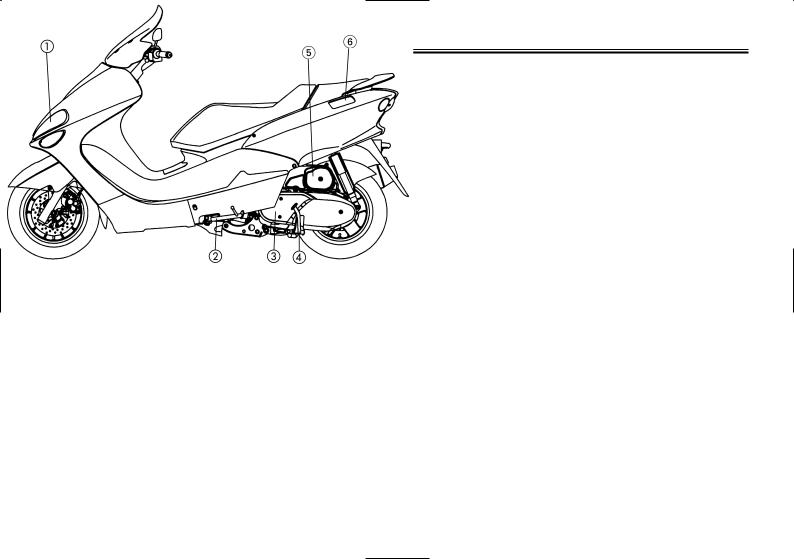
Left view
2
1. |
Headlight (page 6-20) |
4. |
Centerstand (page 6-17) |
2. |
Sidestand (page 3-8) |
5. |
Air filter (page 6-11) |
3. |
V-Belt case air filter (page 6-11) |
6. |
Fuel tank cap (page 3-6) |
2-1
DESCRIPTION
EAU10420
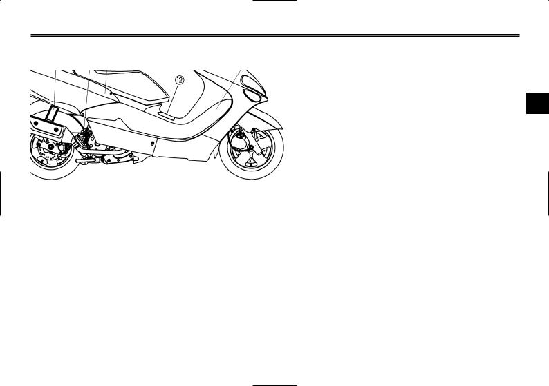
Right view
2
7. |
Passenger handle |
11. |
Storage compartment (page 3-7) |
8. |
Rear shock absorber (page 3-8) |
12. |
Battery/fuse box (page 6-18) |
9. |
Seat (page 3-7) |
13. |
Coolant reservoir (page 6-10) |
10. |
Engine oil dipstick (page 6-7) |
14. |
Radiator |
2-2
DESCRIPTION
EAU10430
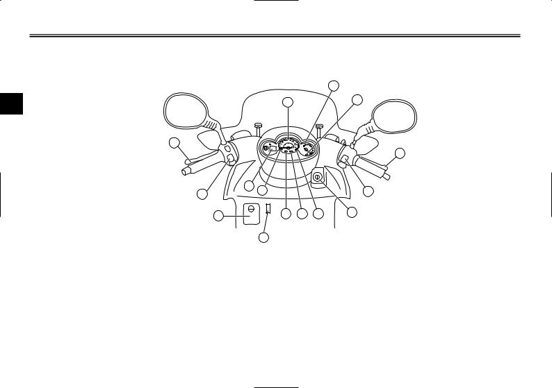
Controls and instruments
|
|
21 |
2 |
17 |
24 |
|
||
|
15 |
|
22
25 |
18 |
|
|
|
23 |
16 |
|
|
|
|
|
27 |
|
19 |
20 |
18 |
26 |
|
28 |
|
|
|
|
15.Rear brake lever (page 3-6)
16.Left handlebar switch (page 3-4)
17.Speedometer (page 3-3)
18.Turn indicator lights (page 3-1)
19.High beam indicator light (page 3-1)
20.Coolant temperature warning light (page 3-1)
21.Fuel gauge (page 3-3)
22.Front brake lever (page 3-5)
23.Right handlebar switch (page 3-4)
24.Battery voltage (page 3-3)
25.Odometer/Clock (page 3-4)
26.Main switch/Steering lock (page 3-1)
27.Front compartment (page 3-7)
28.Coolant level gauge window (page 6-10)
2-3
INSTRUMENT AND CONTROL FUNCTIONS
EAU10450
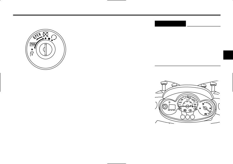
Main switch
The main switch controls the ignition and lighting systems. The various main switch positions are described below.
EAU10630
ON
All electrical systems are supplied with power, and the engine can be started. The key cannot be removed.
EAU10660
OFF
All electrical systems are off. The key can be removed.
EAUM1020
“h”
The coolant temperature warning light should come on when the key is turned to “h”. (See page 3-2.)
EAU10700
LOCK
The steering is locked, and all electrical systems are off. The key can be removed.
To lock the steering
1.Turn the handlebars all the way to the left.
2.Push the key in from the “OFF” position, release it, and then turn it to “LOCK”.
3.Remove the key.
To unlock the steering
Insert the key and turn it to “OFF”.
EWA10060
s WARNING
Never turn the key to “OFF” or “LOCK” while the vehicle is moving, otherwise the electrical systems will be switched off, which may result in loss of control or an
accident. Make sure that the vehi-
3
cle is stopped before turning the key to “OFF” or “LOCK”.
EAU10980
Indicator lights
1 2 1
1.Turn signal indicator lights
2.High beam indicator light
3-1
INSTRUMENT AND CONTROL FUNCTIONS
EAU11030
Turn signal indicator lights “c” and “d”
The corresponding indicator light flashes when the turn signal switch is pushed to the left or right.
EAU11080
3High beam indicator light “j”
This indicator light comes on when the high beam of the headlight is switched on.
EAU11390
Oil change indicator light “z”
12
1.Oil change indicator
2.Coolant temperature warning light
This indicator light comes on at the initial 1000 km (600 mi) and every
3000 km (1800 mi) thereafter to indi-
cate that the engine oil should be changed.
If the engine oil is changed before the oil change indicator comes on (i.e. before the periodic oil change interval has been reached), the indicator light must be reset after the oil change for the next periodic oil change to be indicated at the correct time. (See page 6-8.)
The electrical circuit of the indicator light can be checked according to the following procedure.
1.Set the engine stop switch to “h” and turn the key to “ON”.
2.Check that the indicator comes on for a few seconds and then goes off.
3.If the indicator light does not come on, have a Yamaha dealer check the electrical circuit.
NOTE:
The oil change indicator light may flash when the engine is revved with the scooter on the centerstand, but this does not indicate a malfunction.
EAUM1080
Coolant temperature warning light “y”
This warning light comes on when the engine overheats. When this occurs, stop the engine immediately and allow the engine to cool.
The electrical circuit of the warning light can be checked according to the following procedure.
1.Turn the key to “h”.
2.If the warning light does not come on, have a Yamaha dealer check the electrical circuit.
ECA10020
CAUTION
Do not operate the engine if it is overheated.
3-2
INSTRUMENT AND CONTROL FUNCTIONS
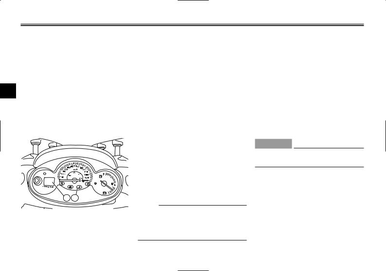
EAU11660
Speedometer unit
1
2
1.Speedomenter unit
2.Odometer
The speedometer unit is equipped with a speedometer, an odometer and a tripmeter. The speedometer shows riding speed. The odometer shows the total distance traveled. The tripmeter shows the distance traveled since it was last set to zero.
Pushing the “TRIP” button switches the display between the odometer mode “ODO” and the tripmeter mode “TRIP”. To reset the tripmeter, enter the “TRIP” mode, and then hold down the “TRIP” button for at least one second. The tripmeter can be used together with the fuel gauge to esti-
mate the distance that can be trave- |
NOTE: |
|
|
||
led with a full tank of fuel. This infor- |
● The odometer/tripmeter reading |
|
|||
mation will enable you to plan future |
mode can be changed any num- |
|
|||
fuel stops. |
ber of times while the odometer |
|
|||
Setting the odometer/tripmeter |
reading is below 10, but it cannot |
|
|||
reading mode |
be changed anymore after the |
|
|||
The odometer and tripmeter can be |
reading has reached 10. |
|
|||
set to count in either miles or kilome- |
● Switching between the mile and |
3 |
|||
ters according to the following proce- |
the kilometer mode does not |
||||
|
|||||
dure. |
change or convert the current |
|
|||
1. |
Turn the key to “ON” while pres- |
odometer/tripmeter reading. |
|
||
|
sing the reset button. |
|
|
|
|
2. |
Release the reset button when |
|
EAUM1100 |
|
|
|
the display comes on. |
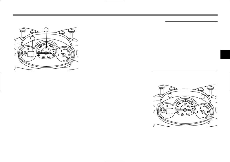
Battery voltage/fuel gauge |
|
||
3. |
The current mode appears in the |
|
|
|
|
|
display: “CONT” (continental) for |
|
|
|
|
|
the kilometer mode and “EnGL” |
2 |
1 |
|
|
|
(English) for the mile mode. |
|
|
||
|
|
|
|
||
4. |
Press the reset button to switch |
|
|
|
|
|
the mode. |
|
|
|
|
5. |
Press the reset button for two |
|
|
|
|
|
seconds to confirm the setting. |
|
|
|
|
1.Fuel gauge
2.Clock
3-3
INSTRUMENT AND CONTROL FUNCTIONS
When the key is turned to “OFF”, the voltage/fuel gauge indicates the battery voltage.
NOTE:
If the battery voltage drops to 10 V, have a Yamaha dealer check the bat-
tery.
3
When the key is turned to “ON”, the voltage/fuel gauge indicates the amount of fuel in the fuel tank after indicating the battery voltage for two seconds. The needle moves towards “E” (empty) as the fuel level decreases. When the needle reaches “E”, refuel as soon as possible.
NOTE:
Do not allow the fuel tank to empty itself completely.
EAU12330
EAUS1210
Clock
To set the clock
1.Turn the key to “ON”.
2.Press the “TRIP” button for two seconds, and the hour display will flash.
3.Press the “TRIP” button to set the hours.
4.Press the “TRIP” button for two seconds, and the first minute digit will flash.
5.Press the “TRIP” button to set the first minute digit.
6.Press the “TRIP” button for two more seconds, and the second minute digit will flash.
7.Press the “TRIP” button to set the second minute digit.
8.Press the “TRIP” button for two seconds to set the clock.
EAU12343
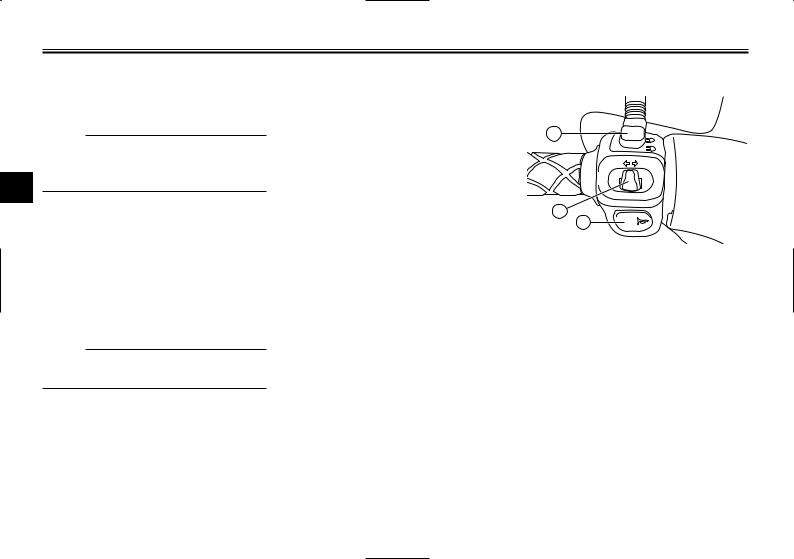
Handlebar switches
1
2
3
1.Dimmer switch “j, k”
2.Turn signal switch “b”
3.Horn switch“a”
EAUS1020
Dimmer switch “j/k”
Set this switch to “j” for the high beam and to “k” for the low beam. With the headlight on low beam, press this switch downwards to flash the headlight.
Anti-theft alarm (optional)
This motorcycle can be equipped with an optional anti-theft alarm by a Yamaha dealer. Contact a Yamaha dealer for more information.
3-4
INSTRUMENT AND CONTROL FUNCTIONS
EAU12460
Turn signal switch “c/d”
To signal a right-hand turn, push this switch to “d”. To signal a left-hand turn, push this switch to “c”. When released, the switch returns to the center position. To cancel the turn signal lights, push the switch in after it has returned to the center position.
EAU12500
Horn switch “a”
Press this switch to sound the horn.
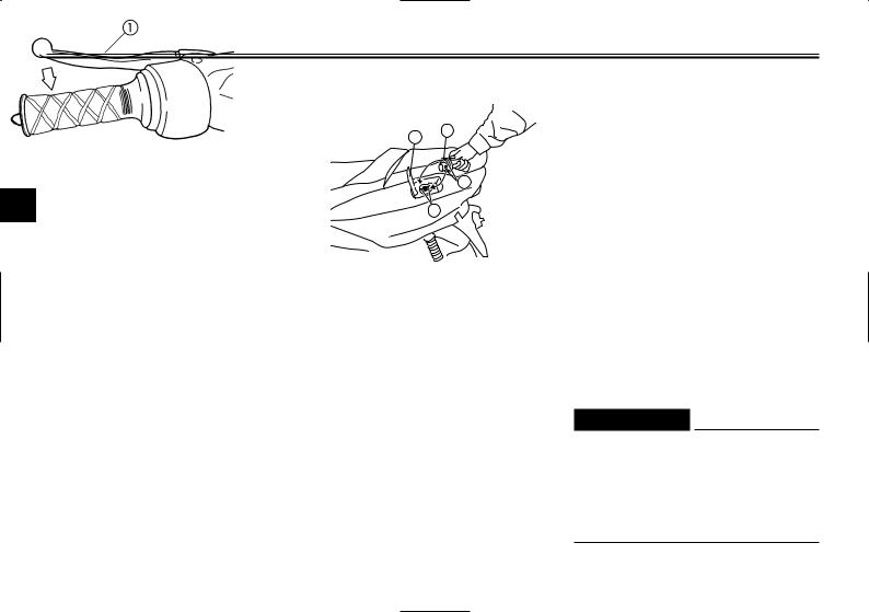
EAU12690
Start switch “g”
Push this switch to crank the engine
with the starter.
ECA10050
CAUTION
See page 5-1 for starting instructions prior to starting the engine.
EAU12763
Hazard switch “  ”
”
1
•
g 2
1.Hazard switch “  ”
”
2.Start switch “g”
With the key in the “ON” position, turn this switch to “  ” to turn on the hazard lights (simultaneous flashing of all turn signal lights).
The hazard lights are used in case of an emergency or to warn other drivers when your vehicle is stopped where it
might be a traffic hazard.
ECA10060
CAUTION
EAU12900
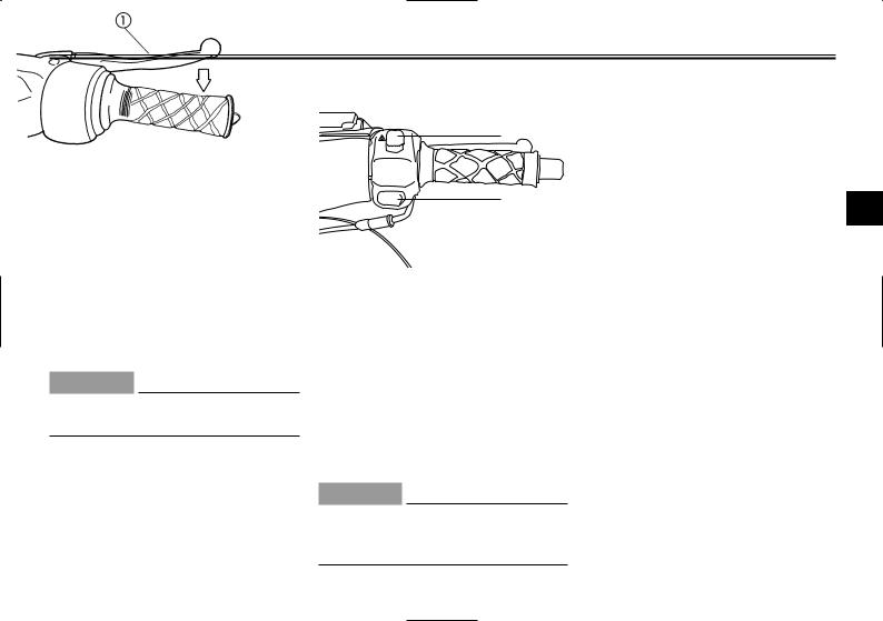
Front brake lever
3
1. Front brake lever
The front brake lever is located on the right handlebar grip. To apply the front brake, pull this lever toward the handlebar grip.
Do not use the hazard light for an extended length of time, otherwisethe battery may discharge.
3-5
INSTRUMENT AND CONTROL FUNCTIONS
EAU12950
Rear brake lever
3
1. Rear brake lever
The rear brake lever is located on the left handlebar grip. To apply the rear brake, pull this lever toward the handlebar grip.
EAUS1040 |
EAU13220 |
Fuel tank cap |
Fuel |
2 3
 1
1
1
1.Aligning marks
2.Fuel tank cover
3.Fuel tank cap
To open the fuel tank cap
1.Open the fuel tank cap cover by pushing in on the rear end of it.
2.Insert the key in the lock and turn it clockwise.
To close the fuel tank cap
1.Align the match marks, and then push the fuel tank cap into the original position.
2.Turn the key counterclockwise and remove it.
3.Close the fuel tank cover.
1.Filling tube
2.Fuel level
Make sure that there is sufficient fuel in the tank. When refueling, be sure to insert the pump nozzle into the fuel tank filler hole and to fill the tank to
the bottom of the filler tube as shown.
EWA10880
s WARNING
●Do not overfill the fuel tank, otherwise it may overflow when the fuel warms up and expands.
●Avoid spilling fuel on the hot engine.
3-6
 Loading...