


WaveRunner GP1200R
ASSEMBLY MANUAL
*LIT186660028*
LIT-18666-00-28 |
F0X-28107-ZA-11 |

E
WaveRunner GP1200R
ASSEMBLY MANUAL
©2000 Yamaha Motor Co., Ltd. 1st Edition, January 2000
All rights reserved. Any reprinting or unauthorized use without the written permission of Yamaha Motor Co., Ltd.
is expressly prohibited. Printed in USA LIT-18666-00-28
PREFACE
This Assembly Manual contains the information needed to assemble the Yamaha water vehicle correctly prior to delivery to the customer. Since some external parts of the water vehicle have not been assemblied at the Yamaha factory for convenience of packing, assembly by the Yamaha dealer is required. It should be noted that the reassembled water vehicle should be thoroughly cleaned, inspected, and adjusted prior to delivery to the customer.
NOTICE
Because Yamaha constantly strives for product improvement, the service specifications may be subject to change in the future. If any change is introduced into the specifications or assembly procedures, Yamaha dealers will be notified by a technical bulletin.
IMPORTANT MANUAL INFORMATION:
Particularly important information is distinguished in this manual by the following notations.
 The safety Alert Symbol means ATTENTION! BECOME ALERT! YOUR SAFETY IS INVOLVED!
 WARNING
Failure to follow WARNING instructions could result in severe injury or death to the machine operator, a bystander, or a person inspecting or repairing the water vehicle.
CAUTION:
A CAUTION indicates special precautions that must be taken to avoid damage to the water vehicle.
NOTE:
A NOTE provides key information to make procedures easier or cleaner.
E
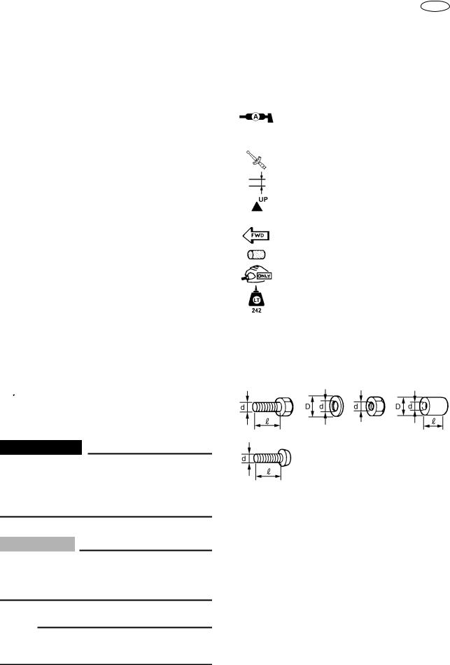
SYMBOLS USED IN THIS
ASSEMBLY MANUAL
In order to simplify descriptions in assembly manuals, the following symbols are used:
:Coat with water resistant grease. (Yamaha grease A, Yamaha marine grease)
:Tightening torque.
:Provide clearance.
:Install so that the arrow mark faces upward.
:Frontword of the water vehicle.
:Made of rubber or plastics.
:Tighten temporarily.
:Apply locking agent.
LOCTITE ‚ No.242 (BLUE LOCTITE)
Size:
d/D : Diameter of part.
R: Length of part.
|
|
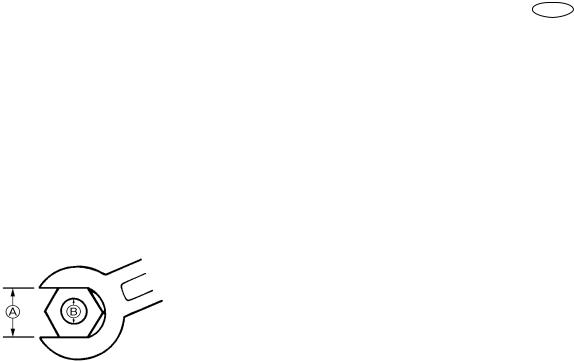
General torque |
||
Nut A |
Bolt B |
specifications |
||
|
|
Nm |
kgf•m |
lb•ft |
|
|
|
|
|
8 mm |
M5 |
5.0 |
0.5 |
3.6 |
10 mm |
M6 |
8.0 |
0.8 |
5.8 |
12 mm |
M8 |
18 |
1.8 |
13 |
14 mm |
M10 |
36 |
3.6 |
25 |
17 mm |
M12 |
43 |
4.3 |
31 |
|
|
|
|
|
|
|
|
|
|
|
|
|
|
|
E
GENERAL TORQUE SPECIFICATIONS
This chart specifies the torques for tightening standard fasteners with standard clean dry ISO threads at room temperature. Torque specifications for special components or assemblies are given in applicable sections of this manual. To avoid causing warpage, tighten multi-fastener assemblies in a criss-cross fashion, in progressive stages until the specified torque is reached.
E
UNPACKING AND CHECKING
Carefully uncrate unit and inventory any missing or damaged parts.
NOTE: For USA:
If concealed damage is found during uncrating, refer to the Yamaha Warranty Handbook, Chapter 3. Documentation may be required for warranty reimbursement. Do not continue with uncrating or throw the crate away until the requirements in Chapter 3 have been met.
COMPARTMENT DIAGRAM
COMPARTMENT PART CHART
No. |
Part name |
Q’ty |
Remarks |
1 |
Water vehicle body |
1 |
|
2 |
Carton box |
1 |
|
|
|
|
|
– 1 –
E
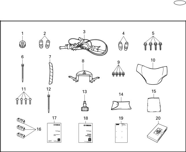
COMPARTMENT DIAGRAM
COMPARTMENT PART CHART
No. |
Part name |
Q’ty |
Part number |
1 |
Grommet |
1 |
F0X-61469-00 |
2 |
Lower handlebar holder |
2 |
EU0-23814-01 |
3 |
Handlebar assembly |
1 |
F0X-U155A-00 |
4 |
Upper handlebar holder |
2 |
EU0-23814-30 |
5 |
Bolt 8 × 55 mm (0.31 × 2.17 in) |
4 |
90119-089UM |
6 |
Band |
1 |
90464-32801 |
7 |
Spiral tube |
1 |
90448-25800 |
8 |
Handlebar cover stay |
1 |
GP7-U142K-00 |
9 |
Screw 6 × 15 mm (0.24 × 0.59 in) |
4 |
90159-069U1 |
10 |
Handlebar cover |
1 |
GP7-U142A-11 |
11 |
Screw 6 × 19 mm (0.24 × 0.75 in) |
4 |
90149-069U9 |
12 |
Band |
1 |
90601-200U2 |
13 |
Flashing conduction fitting |
1 |
67X-12590-00 |
14 |
Tool kit |
1 |
EU0-65986-00 |
15 |
Vinyl bag |
1 |
EU0-65901-01 |
|
|
|
|
16 |
Spark plug |
3 |
94702-00396 |
17 |
Owner’s/Operator’s manual |
1 |
F0X-F8199-10 |
18 |
Riding practice tips |
1 |
F0X-F819T-10 |
19 |
Riding instruction card |
1 |
FN8-U595B-02 |
20 |
Basic orientation video |
1 |
F0D-U595A-00 |
– 2 –
E
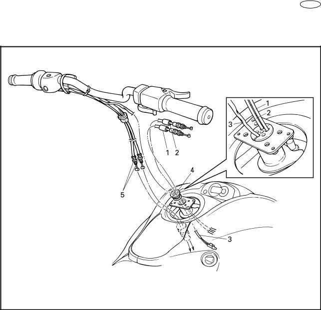
WIRE LEAD AND CABLE ROUTING
EXPLODED DIAGRAM
INSTALLATION CHART
Step |
Procedure/Part name |
Q’ty |
|
|
Service points |
|
|
WIRE LEAD AND CABLE |
|
|
Follow “Step” order for installation. |
||
|
ROUTING |
|
|
NOTE: |
|
|
|
|
|
|
Working from the bow side, open the front |
||
|
|
|
|
hood, and then remove the storage com- |
||
|
|
|
|
partment. |
||
1 |
Choke cable |
1 |
|
|
|
|
|
|
|
|
|||
2 |
Throttle cable |
1 |
|
|
|
|
3 |
Handlebar switch lead |
1 |
|
|
|
|
4 |
Grommet |
1 |
|
NOTE: |
|
|
|
|
|
|
Apply soapy water to the grommet for eas- |
||
|
|
|
|
ier installation. |
||
5 |
QSTS cable |
2 |
|
|
|
|
|
|
|
|
|||
|
|
|
|
|
|
|
– 3 –

E
HANDLEBAR AND THROTTLE CABLE INSTALLATION
EXPLODED DIAGRAM
INSTALLATION CHART
Step |
Procedure/Part name |
Q’ty |
|
|
Service points |
|
|
HANDLEBAR AND THROTTLE |
|
|
Follow “Step” order for installation. |
||
|
CABLE INSTALLATION |
|
|
|
|
|
1 |
Lower handlebar holder |
2 |
|
|
|
|
2 |
Handlebar assembly |
1 |
|
|
|
|
3 |
Upper handlebar holder |
2 |
|
NOTE: |
|
|
|
|
|
|
● Align the punched marks a on the handle- |
||
|
|
|
|
bar with the top surface of the lower han- |
||
|
|
|
|
dlebar holders. |
||
|
|
|
|
● The upper handlebar holder should be |
||
|
|
|
|
installed with the punched mark b forward. |
||
|
|
|
|
|
||
4 |
Bolt (with washer) |
4 |
|
NOTE: |
|
|
|
8 × 55 mm (0.31 × 2.17 in) |
|
|
Tighten the bolts so that the front clearance |
||
|
|
|
|
c of the upper handlebar holder is smaller |
||
|
|
|
|
than the rear clearance d. |
||
|
|
|
|
|
|
|
|
|
|
|
|
|
|
– 4 –
 Loading...