


FCC INFORMATION (U.S.A.)
1.IMPORTANT NOTICE: DO NOT MODIFY THIS UNIT!
This product, when installed as indicated in the instructions contained in this manual, meets FCC requirements. Modifications not expressly approved by Yamaha may void your authority, granted by the FCC, to use the product.
2.IMPORTANT: When connecting this product to accessories and/or another product use only high quality shielded cables. Cable/s supplied with this product MUST be used. Follow all installation instructions. Failure to follow instructions could void your FCC authorization to use this product in the USA.
3.NOTE: This product has been tested and found to comply with the requirements listed in FCC Regulations, Part 15 for Class ”B” digital devices. Compliance with these requirements provides a reasonable level of assurance that your use of this product in a residential environment will not result in harmful interference with other electronic devices. This equipment generates/uses radio frequencies and, if not installed and used according to the instructions found in the users manual, may cause interference harmful to the operation of other electronic devices. Compliance with FCC regulations does not guarantee that interference will not occur in all installations. If this product is found to be the source of interference, which can be determined by turning the unit ”OFF” and ”ON”, please try to eliminate the problem by using one of the following measures:
Relocate either this product or the device that is being affected by the interference.
Utilize power outlets that are on different branch (circuit breaker or fuse) circuits or install AC line filter/s.
In the case of radio or TV interference, relocate/reorient the antenna. If the antenna lead-in is 300 ohm ribbon lead, change the lead-in to co-axial type cable.
If these corrective measures do not produce satisfactory results, please contact the local retailer authorized to distribute this type of product. If you can not locate the appropriate retailer, please contact Yamaha Corporation of America, Electronic Service Division, 6600 Orangethorpe Ave, Buena Park, CA 90620
The above statements apply ONLY to those products distributed by Yamaha Corporation of America or its subsidiaries.
*This applies only to products distributed by YAMAHA CORPORATION OF AMERICA.
Litiumbatteri!
Bör endast bytas av servicepersonal. Explosionsfara vid felaktig hantering.
VAROITUS!
Lithiumparisto, Räjähdysvaara. Pariston saa vaihtaa ainoastaan alan ammattimies.
ADVARSEL!
Lithiumbatteri!
Eksplosionsfare. Udskiftning må kun foretages af en sagkyndig, – og som beskrevet i servicemanualen.
CANADA
THIS DIGITAL APPARATUS DOES NOT EXCEED THE “CLASS B” LIMITS FOR RADIO NOISE EMISSIONS FROM DIGITAL APPARATUS SET OUT IN THE RADIO INTERFERENCE REGULATION OF THE CANADIAN DEPARTMENT OF COMMUNICATIONS.
LE PRESENT APPAREIL NUMERIQUE N’EMET PAS DE BRUITS RADIOELECTRIQUES DEPASSANT LES LIMITES APPLICABLES AUX APPAREILS NUMERIQUES DE LA “CLASSE B” PRESCRITES DANS LE REGLEMENT SUR LE BROUILLAGE RADIOELECTRIQUE EDICTE PAR LE MINISTERE DES COMMUNICATIONS DU CANADA.
*This applies only to products distributed by YAMAHA CANADA MUSIC LTD.
*Ceci ne s’applique qu’aux produits distribués par Yamaha Canada Musique Ltée.
SPECIAL MESSAGE SECTION
This product utilizes an external power supply (adapter). DO NOT connect this product to any power supply or adapter other than one described in the manual, on the name plate, or specifically recommended by Yamaha.
WARNING: Do not place this product in a position where anyone could walk on, trip over, or roll anything over power or connecting cords of any kind. The use of an extension cord is not recommended! If you must use an extension cord, the minimum wire size for a 25’ cord (or 1 cm) is I8 AWG. NOTE: The smaller the AWG number, the larger the current handling capacity. For longer extension cords, consult a local electrician.
This product should be used only with the components supplied, or a cart, rack, or stand that is recommended by Yamaha. If a cart, etc., is used, please observe all safety markings and instructions that accompany the accessory product.
SPECIFICATIONS SUBJECT TO CHANGE: The information contained in this manual is believed to be correct at the time of printing. However, Yamaha reserves the right to change or modify any of the specifications without notice or obligation to update existing units.
Do not attempt to service this product beyond that described in the user-maintenance instructions. All other servicing should be referred to qualified service personnel.
This product, either alone or in combination with an amplifier and headphones or speaker/s, may be capable of producing sound levels that could cause permanent hearing loss. DO NOT operate for long periods of time at a high volume level or at a level that is uncomfortable. If you experience any hearing loss or ringing in the ears, you should consult an audiologist. IMPORTANT: The louder the sound, the shorter the time period before damage occurs.
Some Yamaha products may have benches and/or accessory mounting fixtures that are either supplied with the product or as optional accessories. Some of these items are designed to be dealer assembled or installed. Please make sure that benches are stable and any optional fixtures (where applicable) are well secured BEFORE using. Benches supplied by Yamaha are designed for seating only. No other uses are recommended.
NOTICE: Service charges incurred due to lack of knowledge relating to how a function or effect works (when the unit is operating as designed) are not covered by the manufacturer’s warranty, and are therefore the owner’s responsibility. Please study this manual carefully and consult your dealer before requesting service.
ENVIRONMENTAL ISSUES: Yamaha strives to produce products that are both user safe and environmentally friendly. We sincerely believe that our products and the production methods used to produce them, meet these goals. In keeping with both the letter and the spirit of the law, we want you to be aware of the following:
Battery Notice: This product MAY contain a small non-recharge- able battery which (if applicable) is soldered in place. The average life span of this type of battery is approximately five years. When replacement becomes necessary, contact a qualified service representative to perform the replacement.
This product may also use “household” type batteries. Some of these may be rechargeable. Make sure that the battery being charged is a rechargeable type and that the charger is intended for the battery being charged.
When installing batteries, do not mix old batteries with new, or with batteries of a different type. Batteries MUST be installed correctly. Mismatches or incorrect installation may result in overheating and battery case rupture.
Warning: Do not attempt to disassemble, or incinerate any battery. Keep all batteries away from children. Dispose of used batteries promptly and as regulated by the laws in your area. Note: Check with any retailer of household type batteries in your area for battery disposal information.
Disposal Notice: Should this product become damaged beyond repair, or for some reason its useful life is considered to be at an end, please observe all local, state, and federal regulations that relate to the disposal of products that contain lead, batteries, plastics, etc. If your dealer is unable to assist you, please contact Yamaha directly.
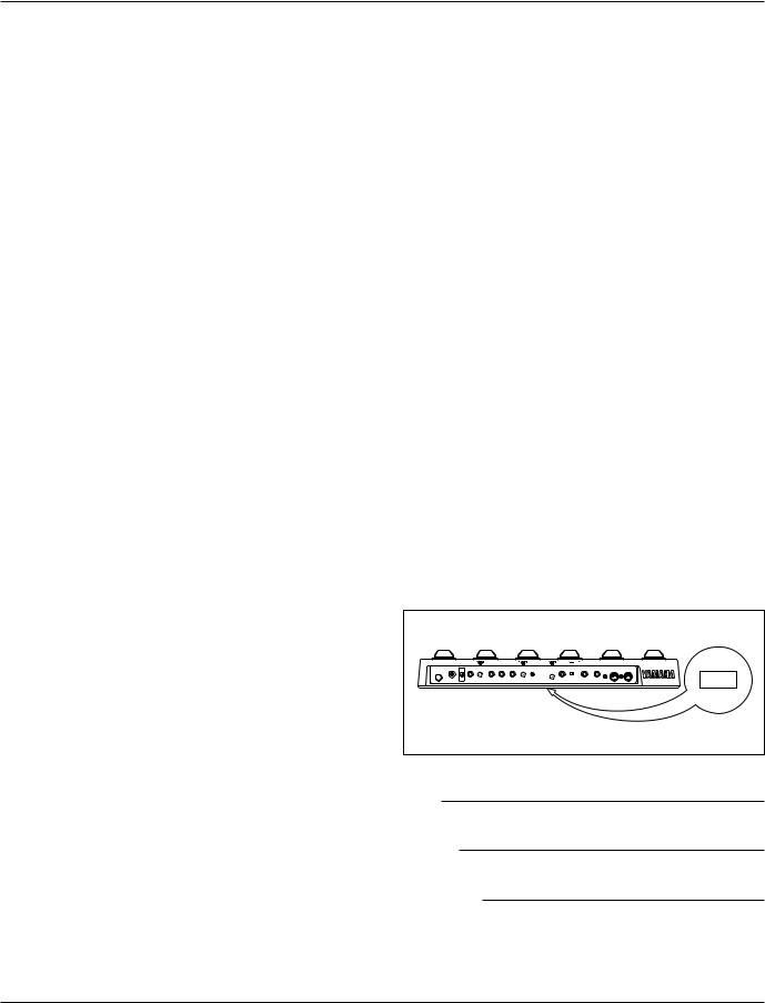
NAME PLATE LOCATION: The graphic below indicates the location of the name plate for this model. The model number, serial number, power requirements, etc., are located on this plate. You should record the model number, serial number, and the date of purchase in the spaces provided below and retain this manual as a permanent record of your purchase.
Model |
Serial No.
Purchase Date
PLEASE KEEP THIS MANUAL
92-BP

Congratulations and thank you for purchasing the Yamaha GW50 Guitar Performance Effector. The GW50 combines high-quality multi effects for guitar (and other instruments as well) with a sophisticated backing section that provides realistic automatic rhythmic accompaniment for you to play along with. The dual functions — effects and backing — make the GW50 useful in a wide range of applications, from live performance and studio use to home recording and individual music practice.
Some of the advanced features of the GW50 include:
Effect Section
■Five basic effect blocks, featuring Compressor, Distortion, Equalizer, Chorus and Reverb/ Delay, plus additional effect types within each block, such as Overdrive, Wah, Amp Simulator, Flanger, Phaser, Pitch Shifter, Tap Delay, and a built-in Noise Gate.
■User memory for storing up to 50 user-created effect programs, all instantly selectable from the convenient Pedal Switches. (See pages 11, 25.)
■High-quality sound in all effects, plus added sonic benefit of having all effects integrated into one unit.
■Comprehensive parameter control over all effects, yet exceptional ease-of-use — you can adjust the main parameters of the effect blocks just as you would on conventional pedal effects.
Backing Section
■A total of 248 automatic rhythm and accompaniment patterns, using realistic drum, bass and other backing instrument sounds. (See page 32.) The automatic accompaniment includes sophisticated chord control, with 25 different chord types available in all keys. (See pages 33-35.)
■Song record capability, for creating songs with the rhythm/accompaniment patterns and chord changes, as well as automating effect program changes, effect bypass and other functions. (See pages 36-38.)
■A special Root Select function (see page 78), which lets you change the root note of the backing chord by playing the note on your guitar, and Triggered Run (see page 82), which allows you to start a song or pattern just by playing a note on your guitar.
Other Features
■Convenient Pedal Switch control over many functions, including chord change, start/stop of pattern/song playback, bypassing of effects, and so on.
■Built-in tuner, allowing you to tune your instrument without removing it from the signal chain. (See page 39.)
■Various MIDI features for interfacing with a wide range of other MIDI devices. (See pages 101-107.)
i
PRECAUTIONS
PRECAUTIONS
■USE THE CORRECT POWER SUPPLY
Power to the GW50 should be supplied only from the appropriate Yamaha AC adaptor (the included PA-3). Use of another adaptor may cause serious damage to the unit. Also make sure that the adaptor you have is appropriate for the AC mains supply voltage in the area where you intend to use the GW50. (The correct input voltage is marked on the adaptor.)
■USE ONLY APPROPRIATE FOOT CONTROLLERS AND FOOTSWITCHES
Certain functions of the GW50 can be controlled by the optional Yamaha FC7 Foot Controller and the FC5 (or FC4) Footswitch. Use of any other pedal or footswitch besides those recommended here may result in erratic operation or may cause some other trouble in the foot controller or footswitch itself.
■ MEMORY BACKUP
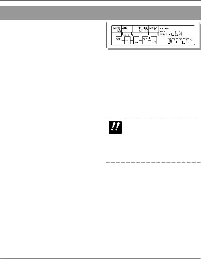
The GW50 memorizes the following data, even when the power is turned off: Memory effect program data, Manual effect data (excepting main parameter values), song data, and general panel settings. The GW50 contains a special long-life lithium battery that retains this data in the internal RAM memory. The battery should last for approximately five years from the date of manufacture. When the backup battery power becomes too low to maintain the memory contents, a warning message appears in the LCD:
(This message appears only when the power is turned on, and stays in the LCD until a panel button is pressed.) When this happens, save all original data to a MIDI data storage device (see note below) or write down all necessary settings to a piece of paper, then have the battery replaced by qualified Yamaha service personnel as soon as possible. DO NOT ATTEMPT TO REPLACE THE BACKUP BATTERY YOURSELF!
BACKING UP DATA—We recommend that you transfer all important data to a MIDI data re- IMPORTANT corder, such as the Yamaha MDF2 MIDI Data Filer or another data storage device, for safe, longterm storage. (For more information, refer to the section on the MIDI Bulk Dump function, page 102.) Yamaha cannot be held responsible for data loss caused by battery failure or improper
operation of the GW50.
■ AVOID PHYSICAL SHOCKS
Although the GW50 has been constructed to withstand the normal rigors of stage and studio use for optimum sturdiness and reliability, avoid subjecting it to strong physical shocks (such as dropping or hitting it), since this may damage the unit. Since the GW50 is a preci- sion-made electronic device, also avoid applying excessive force to the various controls. Also, avoid stepping on any part of the GW50 other than the Pedal Switches, since this may damage or break the controls or glass of the display.
ii PRECAUTIONS

PRECAUTIONS
■AVOID EXCESSIVE HEAT, HUMIDITY, DUST AND VIBRATION
Keep the unit away from locations where it is likely to be exposed to high temperatures (such as direct sunlight) or humidity. Also avoid locations which are subject to excessive dust accumulation or vibration which could cause mechanical damage.
■DO NOT OPEN THE CASE OR ATTEMPT REPAIRS OR MODIFICATIONS YOURSELF
This product contains no user-serviceable parts. Refer all maintenance to qualified Yamaha service personnel. Opening the case and/or tampering in any way with the internal circuitry will void the warranty.
■MAKE SURE POWER IS OFF BEFORE MAKING OR REMOVING CONNECTIONS
Always turn the power off prior to connecting or disconnecting cables.
■HANDLE ALL CONNECTIONS CAREFULLY
Always be careful to connect and disconnect all cables and cords by gripping the connector itself, not by pulling on the cord.
■ CLEAN WITH A SOFT, DRY CLOTH
Never use solvents such as benzine or thinner to clean the unit, since these will damage the finish. Wipe clean with a soft, dry cloth. If necessary, use a soft, clean cloth slightly moistened with a diluted, mild detergent — making sure to wipe the case off again with a dry cloth.
■ ELECTRICAL INTERFERENCE
Since the GW50 contains digital circuitry, it may cause interference and noise if placed too close to TV sets, radios or similar equipment. If such a problem occurs, move the GW50 further away from the affected equipment.
■ MIDI CABLES
When connecting the GW50 to other MIDI equipment, be sure to use only high-quality cables made especially for MIDI data transmission. Also avoid cables longer than 15 meters, since long cables can result in data errors.
PRECAUTIONS iii

TABLE OF CONTENTS
TABLE OF CONTENTS
PRECAUTIONS.................................................... |
ii |
HOW TO USE THIS MANUAL |
|
(READ THIS FIRST!!) ......................................... |
1 |
THE GW50: |
|
WHAT IT IS AND WHAT IT CAN DO ............. |
2 |
PANEL CONTROLS AND TERMINALS .......... |
5 |
ASSIGNABLE BLOCK AND PEDAL |
|
SWITCH FUNCTIONS ................................ |
10 |
GUIDED TOUR (TUTORIAL) — SETTING UP, PLAYING AND USING YOUR GW50
SETTING UP AND PLAYING YOUR |
|
GW50 .................................................................... |
19 |
DEMO MODE — PLAYING THE |
|
DEMONSTRATION SONGS .............................. |
22 |
EFFECT SECTION ............................................... |
24 |
PLAYING WITH SOME OF THE |
|
EFFECTS .......................................................... |
24 |
CHANGING THE SOUND OF |
|
THE EFFECTS ................................................. |
26 |
CHANGING (EDITING) AN EFFECT |
|
PROGRAM AND SAVING IT ........................ |
29 |
USING THE NOISE GATE TO GET |
|
A CLEAN SIGNAL .......................................... |
31 |
BACKING SECTION ........................................... |
32 |
PLAYING PATTERNS — |
|
PATTERN MODE ............................................ |
32 |
PLAYING AND RECORDING SONGS — |
|
SONG MODE ................................................... |
36 |
USING THE BUILT-IN TUNER ......................... |
39 |
REFERENCE/EFFECT SECTION |
|
ABOUT THE MANUAL, MEMORY AND |
|
MEMORY EDIT MODES .................................... |
43 |
MANUAL MODE ................................................. |
44 |
Selecting an Effect Type ............................... |
44 |
Turning Individual Effects On and Off ......... |
44 |
Editing Parameters ........................................ |
44 |
Utility Functions ............................................ |
45 |
Determining the Order of the Effect |
|
Blocks — CONNECT ............................... |
45 |
Bypass Switching of Effect Blocks — |
|
GROUP ..................................................... |
45 |
Setting the Function of the External Foot |
|
Controller — FOOT .................................. |
46 |
Setting the MINIMUM VOLUME Level |
|
(for External Foot Controller and |
|
ASSIGNABLE Block Volume Control) — |
|
MIN VOL .................................................. |
47 |
ASSIGNABLE Block Functions — |
|
MIN/MAX Volume and Auto Volume ......... |
48 |
Setting the AUTO VOLUME Rate — |
|
AUTO VOL .................................................. |
49 |
MANUAL JOB MODE ........................................ |
50 |
Saving the Manual Mode Settings to |
|
an Effect Program ......................................... |
50 |
MEMORY MODE ................................................ |
51 |
Selecting Effect Programs ............................. |
51 |
Checking Parameter Values of the Effect |
|
Program ......................................................... |
51 |
ASSIGNABLE Block and Pedal Switch |
|
Functions ....................................................... |
51 |
Effect Program Selection .......................... |
51 |
Bypass Switching of Effect Blocks .......... |
52 |
iv TABLE OF CONTENTS

TABLE OF CONTENTS
MEMORY EDIT MODE .................................. |
53 |
Compare Mode (Comparing the Edited |
|
Program with the Original) ........................... |
53 |
Saving the Memory Edit Mode Settings to |
|
an Effect Program ......................................... |
53 |
Recalling the Settings of the Original Program |
|
(in Compare Condition) ................................ |
54 |
MEMORY JOB MODE .................................... |
54 |
Copying an Effect Program .......................... |
54 |
Swapping One Effect Program with |
|
Another .......................................................... |
55 |
Naming an Effect Program ........................... |
55 |
Using an External Footswitch ....................... |
56 |
RESTORING FACTORY PRESET EFFECT |
|
PROGRAMS ..................................................... |
57 |
EFFECTS AND PARAMETERS ......................... |
58 |
COMPRESSOR ................................................. |
58 |
DISTORTION ................................................... |
59 |
EQUALIZER ..................................................... |
59 |
CHORUS ........................................................... |
63 |
REVERB/DELAY ............................................. |
66 |
NOISE GATE ................................................... |
69 |
REFERENCE/BACKING SECTION |
|
PATTERN MODE ................................................ |
73 |
Selecting and Playing Patterns ...................... |
73 |
Cursor Control in Pattern Mode .................... |
74 |
Changing Chords ........................................... |
74 |
Changing the Tempo ..................................... |
76 |
Muting the Accompaniment, Bass and |
|
Drums ............................................................ |
76 |
ASSIGNABLE Block and Pedal Switch |
|
Functions in Pattern Mode ............................ |
77 |
Backing Control ........................................ |
77 |
Chord Recall ............................................. |
77 |
Root Select ................................................ |
78 |
SONG MODE ....................................................... |
79 |
SONG PLAY MODE |
|
(SONG PLAYBACK) ....................................... |
79 |
Selecting and Playing Songs ......................... |
79 |
Cursor Control in Song Mode ....................... |
80 |
Changing the Tempo ..................................... |
80 |
Muting the Accompaniment, Bass and |
|
Drums ............................................................ |
80 |
Position Controls ........................................... |
81 |
ASSIGNABLE Block and Pedal Switch |
|
Functions in Song Mode ............................... |
82 |
Backing Control — |
|
Selecting and Playing a Song ................... |
82 |
Triggered Run ........................................... |
82 |
RECORDING AND EDITING SONGS .......... |
83 |
REALTIME RECORDING MODE |
|
(REALTIME RECORDING) ............................ |
83 |
ASSIGNABLE Block and Pedal Switch |
|
Functions in Song Realtime Recording ........ |
86 |
Hints on Realtime Recording ........................ |
87 |
STEP RECORDING MODE |
|
(STEP RECORDING) ....................................... |
88 |
SONG EDIT MODE (SONG EDITING) ......... |
90 |
Viewing Recorded Events ............................. |
90 |
Editing (Changing) Recorded Events ........... |
92 |
Erasing Recorded Events .............................. |
92 |
Set A and Set B Operations .......................... |
92 |
Marking Measure A and Measure B ......... |
92 |
Jumping to Measure A or Measure B ....... |
92 |
Loop (Repeat) Playback (A to B) ............. |
92 |
Loop (Repeat) Recording (A to B) ........... |
93 |
SONG JOB MODE ........................................... |
94 |
Copying Measures Between A and B ........... |
94 |
Deleting Measures Between A and B ........... |
94 |
Naming Songs ............................................... |
95 |
RESTORING FACTORY PRESET SONGS ... |
95 |
TABLE OF CONTENTS v

TABLE OF CONTENTS
REFERENCE/OTHER FUNCTIONS |
|
(TUNER/MIDI) |
|
TUNER MODE ..................................................... |
99 |
MIDI ...................................................................... |
101 |
MIDI BULK TRANSMISSION MODE .......... |
102 |
CHANGING EFFECT PROGRAMS ON |
|
THE GW50 FROM A CONNECTED |
|
DEVICE ............................................................ |
103 |
CHANGING PROGRAMS ON A CONNECTED |
|
DEVICE FROM THE GW50 ........................... |
104 |
TURNING INDIVIDUAL EFFECTS |
|
ON AND OFF FROM A CONNECTED |
|
DEVICE ............................................................ |
104 |
SYNCHRONIZING ANOTHER DEVICE |
|
WITH THE GW50 ............................................ |
105 |
USING THE BACKING PATTERNS |
|
TO PLAY OTHER SOUND MODULES ........ |
106 |
APPENDICES |
|
ASSIGNABLE BLOCK AND PEDAL |
|
SWITCH FUNCTIONS CHART.......................... |
128 |
EFFECT PARAMETER CHART ......................... |
130 |
FACTORY SET MEMORY EFFECT |
|
PROGRAM LIST .................................................. |
132 |
MEMORY EFFECT PARAMETER LIST ........... |
133 |
MANUAL EFFECT FACTORY SET |
|
PARAMETER CHART ........................................ |
143 |
PRESET PATTERN LIST .................................... |
144 |
DRUM AND PERCUSSION SOUNDS |
|
USED FOR DRUM PARTS ................................. |
146 |
FACTORY SET SONG LIST ............................... |
147 |
ERROR MESSAGES |
111 |
MIDI SPECIFICATIONS ..................................... |
148 |
|
|
|
|||
TROUBLESHOOTING |
114 |
|
MIDI IMPLEMENTATION CHART .................. |
150 |
|
|
|
||
SPECIFICATIONS |
117 |
CHART OF CHORD FINGERINGS |
|
|
|
|
|||
|
|
|
FOR GUITAR ....................................................... |
152 |
INDEX ................................................................... |
119 |
|
|
|
|
|
|
USE OF ADVANCED RECORDING TECHNIQUES |
|
|
|
|
– FACTORY SET SONG 1 |
153 |
SUPPLEMENTAL INFORMATION |
|
|
||
|
|
|
|
|
BLOCK DIAGRAM ............................................. |
125 |
DEMO SONG 1-6 – CHORD CHARTS .............. |
156 |
|
JOB TABLE .......................................................... |
126 |
|
|
|
vi TABLE OF CONTENTS

HOW TO USE THIS MANUAL (READ THIS FIRST!)
HOW TO USE THIS MANUAL (READ THIS FIRST!!)
You are probably eager to try out your new GW50 right away and hear what it can do, rather than have to read through a lot of instructions before you can even get a sound out of it.
Before you do anything else, however, you should read the PRECAUTIONS section. This tells you briefly how to care for your new GW50, how to avoid damaging it, and how to ensure long-term, reliable operation.
Next, read through the section The GW50: WHAT IT IS AND WHAT IT CAN DO.
This briefly gives you an overview of the functions of the GW50 and how you can use it effectively.
The bulk of the manual has been organized into two parts: the GUIDED TOUR (TUTORIAL) and the REFERENCE section.
Read the GUIDED TOUR (TUTORIAL) next. It guides you step-by-step in setting up your GW50, connecting it properly, and (most importantly!) getting sound out of it. The section also goes on to take you through some of the more important functions of the GW50, explaining by way of example how to use it.
The REFERENCE section, on the other hand, is a comprehensive guide to all functions. You won’t need (or want) to read through all of it at once, but it is there for you to refer to when you need information about a certain feature or function.
The PANEL CONTROLS AND TERMINALS is also mainly for reference. However, you should read through the parts here concerning the Pedal Switches, since these are particularly useful and convenient in operating the GW50. In general, look through this section to familiarize yourself with the controls, and refer to it when necessary.
The INDEX in the APPENDICES sections at the back of this manual is also very helpful. It lists and gives page numbers for virtually every function, feature, control and terminal found on the GW50, and gives you a quick, easy way to find what you’re looking for.
Other parts of the APPENDICES and SUPPLEMENTAL INFORMATION sections provide additional useful information: lists of all effect programs, patterns and songs of the GW50, a list of error messages, tips on troubleshooting (when something doesn’t work as expected), and other important information.
HOW TO USE THIS MANUAL (READ THIS FIRST!!) 1
THE GW50: WHAT IT IS AND WHAT IT CAN DO
THE GW50: WHAT IT IS AND WHAT IT CAN DO
WHAT IT IS …
Effect and Backing Sections
The GW50 is actually two different devices in one.
On the one hand, it has an Effect section which provides high-quality and easy-to-use multi effects designed especially for processing electric guitar.
On the other, it has a Backing section which provides realistic automatic rhythm, chord and bass patterns for creating your own accompaniment. Moreover, the GW50 includes a built-in tuner for tuning your instrument without having to remove it from the effect chain.
The Effect section has two mode groups: Manual, which lets you use the GW50 effects just as would a normal pedal effect unit, and Memory, which lets you call up preset effect programs and create your own original programs.
The Backing section also has two mode groups: Pattern, which lets you play the various rhythm patterns, and Song, which lets you play pre-pro- grammed songs and create your own original songs.
Modes of the GW50
The tree chart on the next page shows the relationships of the various modes of the GW50. There are four main modes — Manual, Memory, Pattern and Song — indicated by the shaded areas. All other modes are either separate from them (as with Tuner, MIDI Bulk Transmission and Demo) or are subordinate to them.
The Effect and Backing sections are active simultaneously; however, when making adjustments or performing certain operations within a mode in one of the sections, generally you should press the desired mode button ([MANUAL], [MEMORY] or [SONG/PATTERN]) to make sure that the mode is properly called up before attempting the operation.
Functions in Each Mode
Specific functions and operations of the various modes include:
Manual: Changing the parameters of the effects. Manual Job: Storing parameter settings to a pro-
gram.
Memory: Selecting and using an effect program. Memory Edit: Changing the parameters of an
effect program.
Memory Edit Compare: Comparing the sound and values of edited program with the
original.
Memory Job: Copying, swapping and naming effect programs.
Pattern: Playing the patterns of the Backing section.
Song: Playing a song, or using the Step Recording features to edit a song.
Song Realtime Recording: Recording events to a song in realtime.
Song Job: Copying or deleting measures within a song; naming a song.
Keep in mind as you read this manual that the phrase “main modes” refers to the Manual, Memory, Pattern and Song modes, and that “mode buttons” refers to the [MANUAL],
[MEMORY] and [SONG/PATTERN] buttons.
2 THE GW50: WHAT IT IS AND WHAT IT CAN DO
THE GW50: WHAT IT IS AND WHAT IT CAN DO
|
EFFECT SECTION |
|
|
|
|
|
|
|
|
|
|
|
|
|
|
|
|
|
|
||
|
|
|
|
|
|
|
|
|
|
|
|
MANUAL MODE |
|
JOB MODE |
|
|
|
|
|||
|
or |
|
EDIT MODE |
|
COMPARE MODE |
|||||
|
|
|
|
|
|
|
||||
|
|
|
|
|
|
|
||||
|
MEMORY MODE |
|
|
|
or |
|
|
|
|
|
|
|
|
|
|
|
|
|
|||
|
|
|
|
|
|
JOB MODE |
|
|
|
|
|
|
|
|
|
|
|
|
|
|
|
|
|
|
|
|
|
|
|
|
|
|
|
|
|
|
|
|
|
|
|
|
|
|
BACKING SECTION |
|
|
|
|
|
|
|
||
|
|
|
|
|
|
|
|
|
|
|
|
PATTERN MODE |
|
|
|
|
|
|
|||
|
or |
|
REALTIME RECORDING MODE |
|||||||
|
|
|
|
|
|
|||||
|
|
|
|
|
|
|||||
|
SONG MODE |
|
|
or |
|
|
|
|
||
|
|
|
|
|
|
|
||||
|
|
(PLAY / STEP RECORDING / EDIT) |
|
JOB MODE |
|
|
|
|
||
|
|
|
|
|
|
|||||
|
|
|
|
|
|
|
|
|
|
|
|
|
|
|
|
|
|
|
|||
|
|
|
|
|
|
|
|
|
||
|
or |
|
|
|
|
|
|
|||
|
|
|
|
|
|
|
|
|
||
|
TUNER MODE |
|
|
|
|
|
|
|||
|
or |
|
|
|
|
|
Main modes |
|||
|
|
|
|
|
|
|
|
|||
|
MIDI BULK TRANSMISSION MODE |
|
|
|
|
|
||||
|
|
|
|
|
|
|||||
|
or |
|
|
|
|
|
|
|||
DEMO MODE
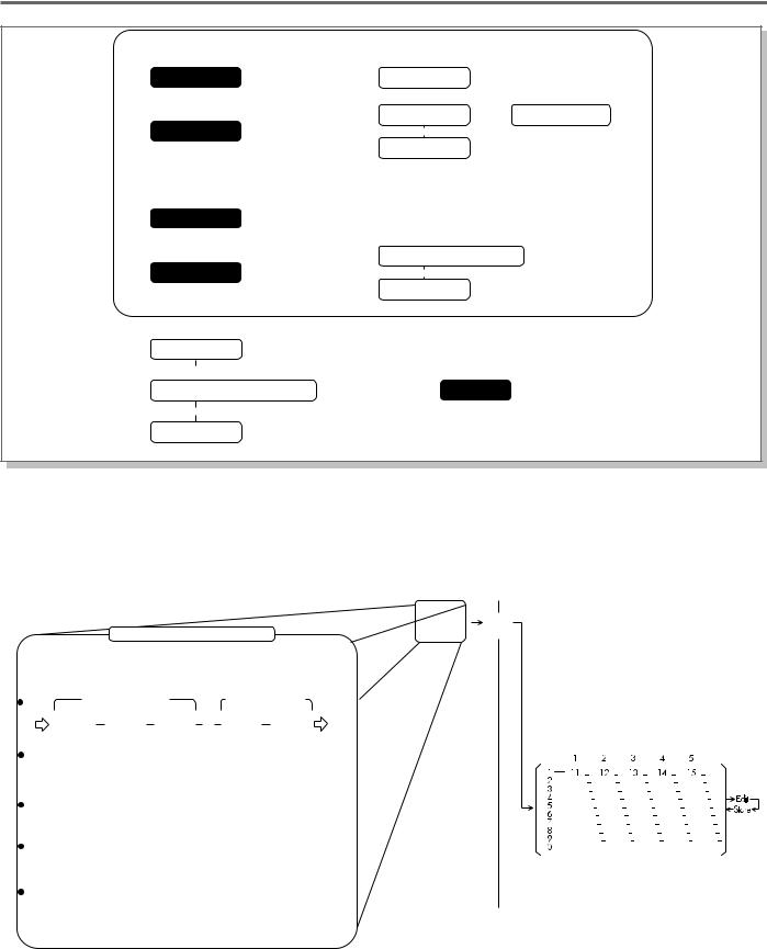
The illustration below shows what comprises an effect program (either Manual or Memory), and
the bank number/program number configuration to which they can be stored.
|
Contents of an Effect Program |
|
|
|
|
Manual Effect Program |
|
Memory Effect Program |
|
||||||||||||||||||||||||||
|
|
|
|
|
|
|
|||||||||||||||||||||||||||||
|
|
|
|
|
|
|
|
|
|
|
|
|
|
|
|
|
|
write |
|
|
|
|
|
|
|
|
|
|
|
|
|
|
|
|
|
|
|
|
|
|
ONE EFFECT PROGRAM |
(store) |
|
|
|
|
|
|
|
|
|
|
|
|
|
|
|
|
|
||||||||||||
|
|
|
|
|
|
|
|
|
|
|
|
|
|
|
|
|
|
|
|
|
|
|
|||||||||||||
|
|
|
|
|
|
|
|
|
|
|
|
|
|
|
|
|
|
|
|
|
There are 50 factory preset memory |
|
|||||||||||||
|
|
|
|
|
|
|
|
|
|
|
|
|
|
|
|
|
|
|
|
|
effect programs. These can be freely |
|
|||||||||||||
|
|
|
|
|
|
|
|
Noise |
|
|
|
|
|
|
|
edited and stored. |
|
||||||||||||||||||
|
EFFECT |
order changeable |
|
Gate |
order changeble |
|
|
|
|
|
|
|
|
|
|
|
|
|
|
|
|
|
|
||||||||||||
|
|
|
|
|
|
|
|
|
|
|
|
|
|
|
|
|
|
|
|
|
|
|
|
|
|||||||||||
|
ORDER |
|
|
|
|
|
|
|
|
|
|
|
|
|
|
|
OUT |
|
|
|
|
|
|
|
|
|
|
|
|
|
|
|
|
|
|
|
IN |
|
Compressor |
|
Distortion |
|
Equalizer |
|
|
|
|
|
|
Chorus |
|
Reverb/Delay |
|
Bank |
|
|
|
|
|
|
|
|
|
|
|
|
|
|
|
||
|
|
|
|
|
|
|
|
|
|
|
|
|
|
|
|
|
|
|
|
|
|
|
|
|
|
|
|||||||||
|
|
|
|
|
|
|
|
|
|
|
|
|
|
|
|
|
|
|
|
|
|
|
|
|
|
|
|
|
|
|
|
|
|
||
|
|
|
|
|
•DIST1 |
|
•Equalizer |
|
|
|
|
|
|
•Chorus 1 |
|
•Reverb |
|
|
|
|
|
|
|
|
|
|
|
|
|
|
|
|
|
||
|
|
|
|
|
|
|
|
|
|
|
|
|
|
|
number |
|
|
|
|
Program number |
|
||||||||||||||
|
EFFECT |
|
|
•DIST2 |
|
•Wah+EQ |
|
|
|
|
|
|
•Chorus 2 |
|
•Delay (Tap) |
|
|
|
|
|
|
|
|||||||||||||
|
|
|
|
|
|
|
|
|
|
|
|
|
|
|
|
|
|
|
|
|
|
|
|
|
|
|
|
|
|
||||||
|
|
|
•DIST3 |
|
•Amp |
|
|
|
|
|
|
•Pitch |
|
•Delay |
|
|
|
|
|
|
|
|
|
|
|
|
|
|
|
|
|
|
|
||
|
TYPE |
|
|
|
|
|
|
|
|
|
|
|
|
|
|
|
|
|
|
|
|
|
|
|
|
|
|
|
|
|
|||||
|
|
|
|
|
•DIST4 |
|
Simulator |
|
|
|
|
|
|
Shifter |
|
+Reverb |
|
|
|
|
|
|
|
|
|
|
|
|
|
|
|
|
|
|
|
|
|
|
|
|
•Overdrive |
|
+EQ |
|
|
|
|
|
|
•Flanger |
|
|
|
|
|
|
|
|
|
|
|
|
|
|
|
|
|
|
|
|
|
|
EFFECT |
|
|
|
|
|
|
|
|
|
|
|
•Phaser |
|
|
|
|
|
|
|
|
|
|
|
|
|
|
|
|
|
|
|
|
|
|
|
PARAMETERS |
|
|
|
|
|
|
|
|
|
|
|
|
|
|
|
|
|
|
|
|
|
|
|
|
|
|
|
|
|
|
||||
|
BYPASS |
|
|
|
|
|
|
|
|
|
|
|
|
|
|
|
|
|
|
|
|
|
|
|
|
|
|
|
|
|
|
|
|
|
|
|
|
|
|
|
|
|
|
|
|
|
|
|
|
|
|
|
|
|
|
|
|
|
|
|
|
|
|
|
|
|
|
|
|
||
|
SETTINGS |
|
|
|
|
|
|
|
|
|
|
|
|
|
|
|
|
|
|
|
|
|
|
|
|
|
|
|
|
|
|
||||
|
OTHER UTILITY |
|
|
|
|
|
|
|
|
|
|
|
|
|
|
|
|
|
|
|
|
|
|
|
|
|
|
|
|
|
|
||||
|
SETTINGS (Group, Foot Controller, Minimum Volume, Auto Volume) |
|
|
|
|
|
|
|
|
|
|
|
|
|
|
|
|
|
|
|
|
||||||||||||||
|
|
|
|
|
|
|
|
|
|
|
|
|
|
|
|
|
|
|
|
|
|
|
|
|
|
|
|
|
|
|
|
|
|
|
|
|
|
|
|
|
|
|
|
|
|
|
|
|
|
|
|
|
|
|
|
|
|
|
|
|
|
|
|
|
|
|
|
|
|
|
|
|
|
|
|
|
|
|
|
|
|
|
|
|
|
|
|
|
|
|
|
|
|
|
|
|
|
|
|
|
|
|
|
|
|
|
|
THE GW50: WHAT IT IS AND WHAT IT CAN DO 3
THE GW50: WHAT IT IS AND WHAT IT CAN DO
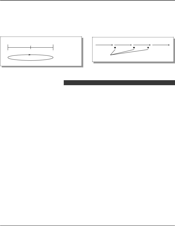
The illustration below shows how the Pattern mode and Song mode are used.
Pattern Mode
In the Pattern mode, individual patterns are played back and repeated.
(for examples, 2 measures)
Song Mode
In the Song mode, the preset patterns can be strung together to create a song. Other events, such as chord changes and muting events, can also be entered.
Pattern A |
|
|
Pattern B |
|||||
|
|
|
|
|
|
|
|
|
|
|
|
|
|
|
|
|
|
Recorded events (chord changes, muting events etc.)
WHAT IT CAN DO …
Here are a few ideas on how you can use your GW50. The list below is in no way comprehensive, but is meant to be a starting point or springboard for your own creative ideas and explorations.
■ All-in-one |
effect unit for |
on the stage, in the |
|
studio, or |
in rehearsal |
With its five effect blocks, the GW50 has all you need to augment your sound, whatever the application. Any or all five effects can be used in virtually any combination as an effect program, and you can instantly select from 50 different effect programs as you play. Plus, flexible effect bypass (on/off) functions give you even more real time control over the sound.
■ Convenient practice tool
The rhythm, bass and accompaniment patterns of the GW50 are perfect for playing along with. By stringing together the rhythm patterns and recording chord changes, you can create and playback complete songs over which you can practice.
Having the full accompaniment behind you is a much more inspiring and exciting way of practicing than using just a metronome.
■Sketchpad for composing and arranging
The accompaniment features can also be used to help you flesh out your own musical ideas. With the wealth of chords (a total of 25 different chord types for each of the 12 keys) and the convenient editing features, the GW50 makes it exceptionally easy to quickly turn your inspirations into complete songs. Plus, the extraordinarily realistic sounds give you the tools to present polished versions of your ideas to others.
Now that you have a basic idea of how the GW50 can help you in your music, go on to the GUIDED TOUR (TUTORIAL), and learn how to set up and use your GW50.
4 THE GW50: WHAT IT IS AND WHAT IT CAN DO
PANEL CONTROLS AND TERMINALS
PANEL CONTROLS AND TERMINALS
This section shows and explains all of the controls and terminals of the GW50. Since the explanations below are fairly brief, you should turn to the page references given for more information on individual buttons and features.
A few general comments:
■Some of the buttons described below must be pressed together to call up a certain function. These are indicated either by a “ +” mark (for example, “ [SHIFT] + [SUB PARAM]”), or by the word “with” (for example, “With
[SHIFT]:”).
■Markings for three of the panel controls which
are used simultaneously with another control — SHIFT , CHORD and B (for the ASSIGN-
ABLE Block Pedal Switch) — are enclosed in a border which indicates the direction(s) in which their companion controls can be found. For example, the CHORD mark points to the right, indicating that the settings below the buttons on the right can be selected by simultaneously pressing CHORD and the appropriate button.
■Also, keep in mind that the function which is enabled — simultaneously holding down
SHIFT , CHORD or |
B , and pressing that |
button — is always printed |
below the button. |
■The buttons whose primary functions are indicated in boxed titles above each button ([MANUAL], [MEMORY] and [SONG/PATTERN]) are referred to as the “mode buttons” and can be conveniently used as exit buttons to “escape” from most in-progress operations (such as Copying, Naming, MIDI Bulk Transmission, etc.).
■All controls that are used to increase or decrease values feature continuous and rapid operation, to let you more quickly and easily reach a desired value. With the [–]/[+] buttons, hold down one button to continuously move through the values and, while holding down that button, press the other to increase the speed. Releasing the second button returns to normal speed. With Pedal Switches 1 and 2 (when used for [–]/[+] control) and the Position Control buttons (<, >, etc.), holding down the appropriate control moves through the values with increasing speed.
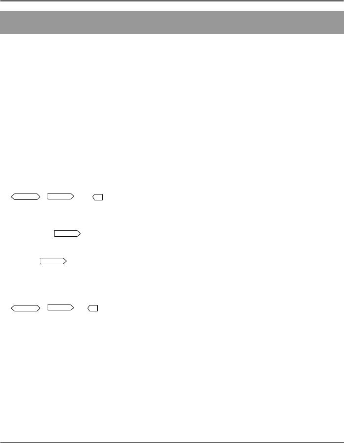
PANEL CONTROLS AND TERMINALS 5
PANEL CONTROLS AND TERMINALS
■ TOP PANEL
|
|
|
|
|
|
|
|
|
20 |
21 |
|
|
|
|
|
|
|
|
|
|
|
|
|
|
|
|
|
s |
|
|
|
|
|
|
|
|
|
22 |
|
|
|
|
|
|
|
|
|
|
|
|
|
|
|
|
|
|
|
|
|
14 |
15 |
16 |
|
|
4 |
|
|
|
|
|
|
|
|
|
17 |
18 |
19 |
5 |
6 |
7 |
8 |
9 |
10 |
11 |
12 |
13 |
|
|
|
|
2
 23
23
1
24
3
1Effect Type Switch
• For selecting the different effect types available in each effect block. These are active only in the Manual and Memory Edit modes. (See pages 26, 44.)
2Parameter Knobs
• For adjusting the main parameters of the effects. These are active only in the Manual and Memory Edit modes. (See page 26.)
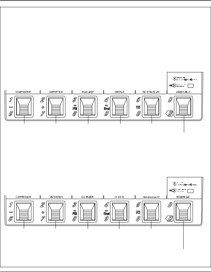
3Effect Block Pedal Switches
• The Pedal Switches have different functions depending on the mode selected.
In Manual mode: For turning individual effect blocks (or groups) on and off. (See page 11.)
In Memory mode: For selecting effect programs and changing the banks of the effect programs. (See page 11.) Also, when ASSIGNABLE Pedal Switch has been pressed twice quickly, for turning individual effect blocks (or groups) on and off. (See page 11.)
In Memory Edit mode: For selecting which effect blocks are active in an effect program. (See page 11.)
In Pattern mode: For performing various control functions, such as (when BACKING CONTROL is selected) selecting patterns, starting or stopping a pattern, or (in CHORD RECALL) changing to pre-assigned chords. (See page 12.)
In Song mode (playback): For performing various control functions, such as: selecting songs, fast forwarding/rewinding within a song, starting/stopping songs. (See page 13.)
In Song mode (recording): For starting or stopping song recording and selecting preassigned chords. (See page 13.)
• The REVERB/DELAY Pedal Switch is also used as a delay time tap control. (See page 67.)
For more information on the Pedal Switches, see the boxed section “ASSIGNABLE BLOCK AND PEDAL
SWITCH FUNCTIONS” on pages 10-14.
6 PANEL CONTROLS AND TERMINALS

PANEL CONTROLS AND TERMINALS
4MANUAL (TUNER)
•For selecting the Manual mode. Pressing this button in any operating condition calls up the Manual mode.
•With [SHIFT]: For selecting the Tuner function. (See pages 39, 99.)
5MEMORY (COPY/NAME)
•For selecting the Memory mode. Pressing this button in any operating condition calls up the Memory mode.
•With [SHIFT]: For calling up (and toggling between) the Effect Copy, Effect Swap and Effect Name operations.
6EDIT/COMPARE (MIDI BULK)
•In Memory mode: Selects the Memory Edit mode, and serves as a Compare switch to toggle between the newly edited settings of an effect program and its original settings (the LED flashes in the Compare condition). (See pages 29, 53.)
•With [SHIFT]: For calling up the MIDI Bulk Transmission operation. (See page 102.)
7Effect Utility Switch
(CONNECT … AUTO VOL)/(SUB PARAM)
• For selecting the miscellaneous Utility functions of the GW50:
■CONNECT — For determining the order of the effect blocks. (See page 45.)
■GROUP — For simultaneously switching several effect blocks on/off. (See page 45.)
■FOOT (Foot Controller) — For determining how the optional FC7 Foot Controller is used. (See pages 46, 47.)
■MIN VOL (Minimum Volume) — For determining the minimum volume setting for the optional FC7 Foot Controller and the ASSIGNABLE Block Pedal Switch (which can be used to instantly change between minimum and maximum volume). (See page 47.)
■AUTO VOL (Auto Volume) — ASSIGNABLE Block Pedal Switch can be used to gradually fade up volume at the rate set here. (See page 49.)
•With [SHIFT]: For calling up Noise Gate effect parameter. (See pages 31, 69.) This also calls up the sub parameters of the Equalizer, Chorus and Reverb/Delay effects. (See page 44.)
8~# Position Control Buttons
8~@ Effect Selector Buttons
8CMP/<< (SONG NAME)
•After pressing [SHIFT] + [SUB PARAM]: Calls up Noise Gate parameter.
•In Connect and Group functions: Selects Compressor effect block.
•In Song mode: For moving to the top of the current or last measure. Hold down for rapid operation.
•In Song mode, with [v]: For returning to the beginning of a song.
9DST/< (MEAS DEL)
•After pressing [SHIFT] + [SUB PARAM]: Calls up Noise Gate parameter.
•In Connect and Group functions: Selects Distortion effect block.
•In Song mode: For moving backward in 16thnote steps. Hold down for rapid operation.
•In Song mode (with [SHIFT]): For deleting a selected range of measures from a song.
•In Song mode, with [n]: For returning to the beginning of a song.
0EQ/> (MEAS COPY)
•After pressing [SHIFT] + [SUB PARAM]: Calls up Equalizer Sub parameters.
•In Connect and Group functions: Selects Equalizer effect block.
•In Song mode: For moving forward in 16thnote steps. Hold down for rapid operation.
•In Song mode, with [ >>]: For moving to the end (last recorded event) of a song.
•In Song mode (with [SHIFT]): For copying a selected range of measures in a song.
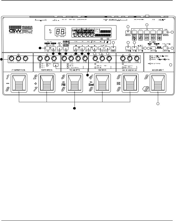
PANEL CONTROLS AND TERMINALS 7
PANEL CONTROLS AND TERMINALS
|
|
|
|
|
|
|
|
|
20 |
21 |
|
|
|
|
|
|
|
|
|
|
|
|
|
|
|
|
|
s |
|
|
|
|
|
|
|
|
|
22 |
|
|
|
|
|
|
|
|
|
|
|
|
|
|
|
|
|
|
|
|
|
14 |
15 |
16 |
|
|
4 |
|
|
|
|
|
|
|
|
|
17 |
18 |
19 |
5 |
6 |
7 |
8 |
9 |
10 |
11 |
12 |
13 |
|
|
|
|
2
 23
23
1
24
3
!CHO/>> (ERASE)
•After pressing [SHIFT] + [SUB PARAM]: Calls up Chorus Sub parameters.
•In Connect and Group functions: Selects Chorus effect block.
•In Song mode: For moving to the top of the next measure. Hold down for rapid operation.
•In Song mode, with [>>]: For moving to the end (last recorded event) of a song.
•In Song mode (with [SHIFT]): For erasing the recorded event(s) at a specific position in a song.
@REV/SET-A (JUMP-A)
•After pressing [SHIFT] + [SUB PARAM]: Calls up Reverb/Delay Sub parameters.
•In Connect and Group functions: Selects Reverb/Delay effect block.
•In Song mode: For setting the “A” mark in a song. Pressing [SHIFT] + [JUMP-A] jumps to the A-marked measure.
#Foot Controller/SET-B (JUMP-B)
•In the Foot (Foot Controller) function: For determining how the connected foot controller is used. (See page 46.)
•In Song mode: For setting the “B” mark in a song. Pressing [SHIFT] + [JUMP-B] jumps to the B-marked measure.
$SHIFT
• For selecting the shifted-state functions, indicated by the names printed below the appropriate buttons. Hold down this button and simultaneously press the appropriate button. (The arrow marks printed with the button name indicate the direction in which the appropriate buttons can be found.)
%– (ACCOMP)
• For decreasing a selected parameter value (as described for the modes below). Hold down for rapid operation.
8 PANEL CONTROLS AND TERMINALS

PANEL CONTROLS AND TERMINALS
In Song/Pattern mode: For decreasing the value at the cursor position (for example, Tempo or Pattern).
In Memory mode: For moving backward through the effect programs, one by one (when the cursor arrow is not shown in the display).
In Manual and Memory Edit mode (sub parameters, MIN VOL, and AUTO VOL): For decreasing the value of the selected sub parameter (when the cursor arrow is at the bottom of the display).
•With [SHIFT] (in the Song/Pattern modes):
For turning the sound of the Backing Accompaniment on and off, while the song or pattern is playing.
^+ (BASS)
•For increasing a selected parameter value (as described for the modes below). Hold down for rapid operation.
In Song/Pattern mode: For increasing the value at the cursor position (for example, Tempo or Pattern).
In Memory mode: For moving forward through the effect programs, one by one (when the cursor arrow is not shown in the display).
In Memory Edit mode (sub parameters, MIN VOL, and AUTO VOL): For increasing the value of the selected sub parameter (when the cursor arrow is at the bottom of the display).
•With [SHIFT] (in the Song/Pattern modes):
For turning the sound of the Backing Bass on and off, while the song or pattern is playing.
&6 CURSOR (DRUMS)
•In Song/Pattern modes: For moving the cursor arrow in the display.
•With [SHIFT] (in Song/Pattern modes): For turning the sound of the Backing Drums on and off, while the song or pattern is playing.
*SONG/PATTERN (SONG REC)
•For switching between the Song and Pattern modes. The LED of the selected function lights.
•With [SHIFT]: For enabling realtime recording of a song (the LED flashes to indicate record standby). (See pages 37, 84.)
(START/STOP (A-B REPEAT )
)
•For starting/stopping the Backing Song or Pattern (the LED flashes).
•With [SHIFT]: For enabling the Repeat function. (See pages 92, 93.)
)CHORD
• Similar to [SHIFT], for selecting the secondary (lower) functions of the Chord buttons. The arrow mark pointing right (printed with the button name) indicates the direction in which the appropriate buttons can be found. (For details on this and other chord-related functions, refer to pages 74-76.)
qChord Buttons
•For selecting the chord root note, or (after pressing [CHORD] + [on/ROOT]) for selecting the bass note.
•With [CHORD]: For selecting the chord type.
wENTER (on/ROOT)
•In Song mode (step recording): For recording or entering event data to a song.
•With [CHORD]: For enabling selection of the bass note.
PANEL CONTROLS AND TERMINALS 9
PANEL CONTROLS AND TERMINALS
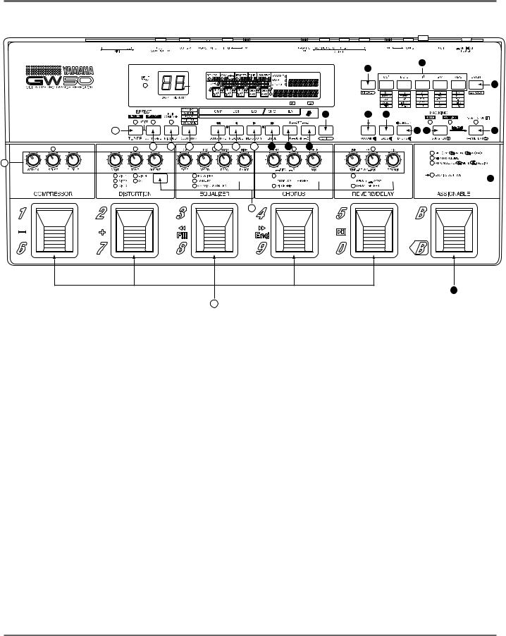
LCD Display
2 4
 s3
s3 


1 |
4 |
1 INPUT PEAK indicator — for monitoring the input signal level (lights continuously when level is too high).
2 BANK/MEMORY indicator — displays the memory bank and program numbers. When selecting songs, this briefly displays the song number. In the Tuner function, this displays the string number (when an open string is played) and/or the name of the note played (for example, 6E).
3 Sharp indicator — This flashes when a sharp note (for example, G or C ) is played in the tuner function.
4 6 — This cursor arrow points to a value in the display that can currently be changed by using the [–]/[+] buttons.
When [MANUAL] or [MEMORY] are pressed (calling up the Effect mode display), the arrow automatically disappears from the display. You can use [6 CURSOR] to move the cursor arrow back “in” the display. When [SONG/PATTERN] is pressed (calling up the Backing mode display), the cursor automatically appears in the display.
Note: Other display indications are explained later in the relevant sections of the manual.
ASSIGNABLE Block Controls
eASSIGNABLE Block Type Switch
• For selecting various control functions for the ASSIGNABLE Block Pedal Switch and the other Pedal Switches including effect program selection, turning individual effect blocks (or groups) on and off, MIN/MAX Volume, Auto Volume, Backing Control and Chord Recall.
rASSIGNABLE Block Pedal Switch
• For performing various control functions, including effect program selection, turning individual effect blocks (or groups) on and off, MIN/MAX Volume, Auto Volume, Backing Control and Chord Recall. (The arrow mark printed with the button name at the bottom left indicates the direction in which the appropriate buttons can be found.)
For more information on the ASSIGNABLE Block Pedal Switch and the other Pedal Switches, see the section “ASSIGNABLE BLOCK AND PEDAL SWITCH FUNCTIONS” on pages 10-14.
ASSIGNABLE BLOCK AND PEDAL SWITCH FUNCTIONS
ABOUT THE ASSIGNABLE BLOCK LED INDICATORS
LED status
:Lit
:Flashing
:Off
The following illustration shows how and under what conditions the ASSIGNABLE block LEDs are lit.
Indicates bank/ |
|
|
Indicates effect |
Off |
program number |
|
(or effect group) can |
||
|
(not active). |
|||
can be selected. |
|
be turned on/off. |
||
|
|
|||
Indicates maximum |
Indicates minimum |
Off |
||
volume. |
|
|
volume. |
(not active). |
Indicates maximum |
|
Indicates mute |
Off |
|
volume. |
|
or fade-in condition. |
(not active). |
|
On |
|
Indicates Triggered |
Off |
|
(active). |
Run standby condition. |
(not active). |
||
On |
|
Off |
|
|
(active). |
(not active). |
|||
MEMORY ( BANK)/
  x2 ON•OFF
MIN/MAX VOLUME
AUTO VOLUME ( MUTE
MUTE  FADE IN)
BACKING CONTROL
CHORD RECALL
When [MANUAL] is pressed
Note: The MEMORY LED above will still be lit or flashing, even if either of these is on.
the MEMORY LED here flashes, and no other LED in this block is lit.
When [MEMORY] is pressed |
|
only the MEMORY LED here is lit or flashing. |
||
|
||||
When [SONG/PATTERN] is pressed |
|
|
only the BACKING CONTROL LED is lit. |
|
|
|
|||
When [SHIFT] + [SONG REC] |
|
|
only the CHORD RECALL LED is lit. |
|
|
|
|||
are pressed |
|
|
||
10 PANEL CONTROLS AND TERMINALS
PANEL CONTROLS AND TERMINALS
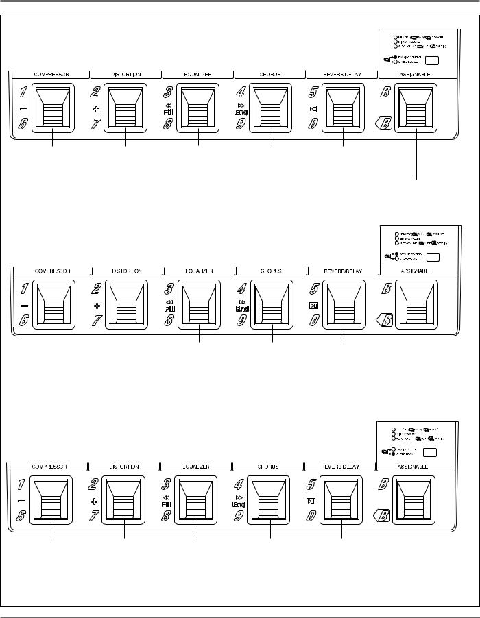
ABOUT THE PEDAL SWITCHES
The Pedal Switches have many different functions, depending on the ASSIGNABLE block settings (indicated by the LEDs in the ASSIGNABLE block) and the selected mode. The following panel illustrations and explanations should help you in understanding how the Pedal Switches are used.
In the Manual, Memory* and Memory Edit modes:
When switching on/off individual effect blocks (or Groups) is enabled —
*Available in Memory mode only when ASSIGNABLE Block Pedal Switch has been pressed twice quickly (enabling effect on/off control).
Memory LED flashes. 


Turns Compressor |
Turns Distortion |
Turns Equalizer |
Turns Chorus |
(or selected Group) |
(or selected Group) |
(or selected Group) |
(or selected Group) |
on or off. |
on or off. |
on or off. |
on or off. |
Turns Reverb/Delay (or selected Group)
on or off. In Memory mode, pressing once enables effect program selection with Pedal Switches 1–5. For controlling MIN/MAX VOLUME or AUTO VOLUME (when either of those functions have been selected with the type switch).
In the Memory mode:
When selection of effect bank number/program number is enabled —
Memory LED is lit continuously. 


Selects effect program number 1 (for the current bank); with the ASSIGNABLE Block Pedal Switch, selects bank 1 or 6.
Selects effect program number 2 (for the current bank); with the ASSIGNABLE Block Pedal Switch, selects bank 2 or 7.
Selects effect program |
Selects effect program |
Selects effect program |
number 3 (for the |
number 4 (for the |
number 5 (for the |
current bank); with the |
current bank); with the |
current bank); with the |
ASSIGNABLE Block |
ASSIGNABLE Block |
ASSIGNABLE Block |
Pedal Switch, selects |
Pedal Switch, selects |
Pedal Switch, selects |
bank 3 or 8. |
bank 4 or 9. |
bank 5 or 0. |
Pressing this once and pressing another Pedal Switch selects banks 1 – 5. Holding this and pressing another Pedal Switch selects banks 6 – 0.
Pressing twice quickly enables Pedal Switch control over on/off of individual effect or selected Group. For controlling MIN/MAX VOLUME or AUTO VOLUME (when either of those functions have been selected with the type switch).
PANEL CONTROLS AND TERMINALS 11
PANEL CONTROLS AND TERMINALS
In the Pattern mode:
With BACKING CONTROL selected — When pattern is stopped:
Decreases pattern |
Increases pattern |
number by 2 |
number by 2 (every |
(every other odd |
other odd numbered |
numbered pattern). |
pattern). |
Starts pattern playback.
Pressing once selects CHORD RECALL; holding this and pressing one of Pedal Switches 1 – 4 assigns current chord to the pressed Pedal Switch. Holding this enables the Root Select function (see page 78).
When pattern is playing back:
Decreases pattern |
Increases pattern |
Plays fill in pattern. Plays ending pattern |
Stops pattern |
number by 2 |
number by 2 |
(then stops playback). |
playback. |
(every other odd |
(every other odd |
|
|
numbered pattern). |
numbered pattern). |
|
|
Pressing once selects CHORD RECALL; holding this and pressing one of
Pedal Switches 1 – 4 assigns current chord to the pressed Pedal Switch.
Holding this enables the Root Select function (see page 78).
In the Pattern mode:
With CHORD RECALL selected —
Plays chord 1 (with |
Plays chord 2 (with |
Plays chord 3 (with |
Plays chord 4 (with |
Starts/stops pattern |
ASSIGNABLE Pedal |
ASSIGNABLE Pedal |
ASSIGNABLE Pedal |
ASSIGNABLE Pedal |
playback. |
Switch; assigns |
Switch; assigns |
Switch; assigns |
Switch; assigns |
|
chord 1). |
chord 2). |
chord 3). |
chord 4). |
|
Pressing once selects BACKING CONTROL; holding this and pressing one of Pedal Switches 1 – 4 assigns current chord to the pressed Pedal Switch. Holding this enables the Root Select function (see page 78).
12 PANEL CONTROLS AND TERMINALS
PANEL CONTROLS AND TERMINALS
In the Song mode (playback):
With BACKING CONTROL selected —
When song is stopped:
Decreases song |
Increases song |
Moves to previous |
Moves to next |
Starts song playback. |
number by 1. |
number by 1. |
measure. |
measure. |
|
Holding this and pressing Pedal Switch 5 enables
Triggered Run function (see page 82).
When song is playing back:
Moves to beginning |
Moves to |
Stops song playback. |
of current measure. |
next measure. |
|
In the Song Realtime Recording mode:
With CHORD RECALL selected —
Plays chord 1. |
Plays chord 2. |
Plays chord 3. |
Plays chord 4. |
Starts/stops song |
|
|
|
|
recording. |
PANEL CONTROLS AND TERMINALS 13

PANEL CONTROLS AND TERMINALS
*The following chart shows which ASSIGNABLE Block functions are available in which modes. Also refer to the section “ASSIGNABLE BLOCK AND PEDAL SWITCH FUNCTIONS CHART” on page 128.
ASSIGNABLE Block function |
Manual |
Memory |
Memory |
Pattern |
Song |
Song Realtime |
||
Edit |
Recording |
|||||||
|
|
|
|
|
|
|||
|
|
|
|
|
|
|
|
|
MEMORY: BANK/NUMBER select |
× |
● |
× |
— |
— |
— |
||
|
|
|
|
|
|
|
|
|
MEMORY: ON/OFF |
● |
or |
● |
— |
— |
— |
||
|
|
|||||||
● |
||||||||
|
|
|
|
|
|
|
|
|
MIN/MAX VOLUME |
● |
● |
● |
— |
— |
— |
||
|
|
|
|
|
|
|
|
|
AUTO VOLUME |
● |
● |
● |
— |
— |
— |
||
|
|
|
|
|
|
|
|
|
BACKING CONTROL |
— |
— |
— |
● |
● |
× |
||
|
|
|
|
|
|
|
|
|
CHORD RECALL |
— |
— |
— |
● |
× |
● |
||
|
|
|
|
|
|
|
|
|
● : Available |
|
|
|
|
|
|
|
|
× : Not available |
|
|
|
|
|
|
|
|
— : Not relevant (to this mode)
Shaded sections indicate settings that are automatically selected when the corresponding mode buttons are pressed.
14 PANEL CONTROLS AND TERMINALS
PANEL CONTROLS AND TERMINALS
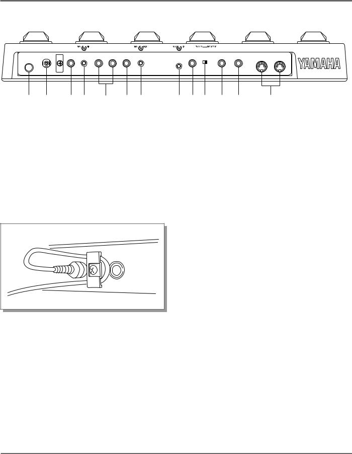
■ REAR PANEL
1 2 3 4 5 6 7 |
8 9 0 ! @ # |
1POWER ON/OFF Switch
2DC IN Terminal
For connection to the supplied PA-3 AC adaptor.
The cable clip located next to this terminal helps to prevent accidental unplugging of the power supply during use. Wrap the adaptor cord firmly around the clip (as shown at right).
3PHONES Jack
For output of both the Backing sound (mono) and the instrument/effect sound (stereo) to a set of stereo headphones.
4Headphone LEVEL Control
For adjusting only the headphone output; this does not affect the output of the other output jacks.
5L/L+R OUTPUT and R OUTPUT Jacks
For stereo or mono output of the instrument/ effect sound. Connect both of these to the corresponding left and right channels of your stereo amplification system to take full advantage of the stereo effects of the GW50. For mono operation, connect your system to the L/L+R jack; this provides a mono mix of the instrument/effect sound.
6BACKING/MONO OUTPUT Jack
When only this output jack is connected, this outputs a mono mix of the Backing Accompaniment, Bass and Drums sound, plus the input instrument/effect sound. When the other output(s) are also connected, only the Backing sound is output from this jack.
7BACKING LEVEL Control
For adjusting the level of the Backing Accompaniment, Bass and Drums output.
8Input LEVEL Control
For adjusting the level of the input signal.
9INPUT Jack
For connection of an instrument (guitar, bass, etc.). (See pages 19, 20 for more information on input/output connections.)
PANEL CONTROLS AND TERMINALS 15

PANEL CONTROLS AND TERMINALS
0LCD SETTING Switch
Two-position (Floor/Desktop) switch for setting the display contrast for optimum
viewing.
!FOOT SW Jack
For connection of an optional footswitch (Yamaha FC5 or FC4), for controlling certain functions and parameters as you play. (See pages 56, 57.)
@FOOT CONTROLLER Jack
For connection of an optional foot controller (Yamaha FC7), for controlling certain functions and parameters as you play. (See page 46.)
#MIDI IN/OUT Terminals
For connection of MIDI cables, when using the GW50 with other MIDI devices. (See page 101.)
16 PANEL CONTROLS AND TERMINALS

GUIDED TOUR (TUTORIAL) — SETTING UP, PLAYING AND
USING YOUR GW50
SETTING UP AND PLAYING YOUR |
|
GW50 .................................................................... |
19 |
DEMO MODE — PLAYING THE |
|
DEMONSTRATION SONGS .............................. |
22 |
EFFECT SECTION ............................................... |
24 |
PLAYING WITH SOME OF THE |
|
EFFECTS .......................................................... |
24 |
CHANGING THE SOUND OF |
|
THE EFFECTS ................................................. |
26 |
CHANGING (EDITING) AN EFFECT |
|
PROGRAM AND SAVING IT ........................ |
29 |
USING THE NOISE GATE TO GET |
|
A CLEAN SIGNAL .......................................... |
31 |
BACKING SECTION ........................................... |
32 |
PLAYING PATTERNS — |
|
PATTERN MODE ............................................ |
32 |
PLAYING AND RECORDING SONGS — |
|
SONG MODE ................................................... |
36 |
USING THE BUILT-IN TUNER ......................... |
39 |

GUIDED TOUR (TUTORIAL)
18 SETTING UP AND PLAYING YOUR GW50
GUIDED TOUR (TUTORIAL)
SETTING UP AND PLAYING YOUR GW50
Once you’ve taken your GW50 out of the box and are ready to use it, follow the simple instructions below in making the connections and setting it up.
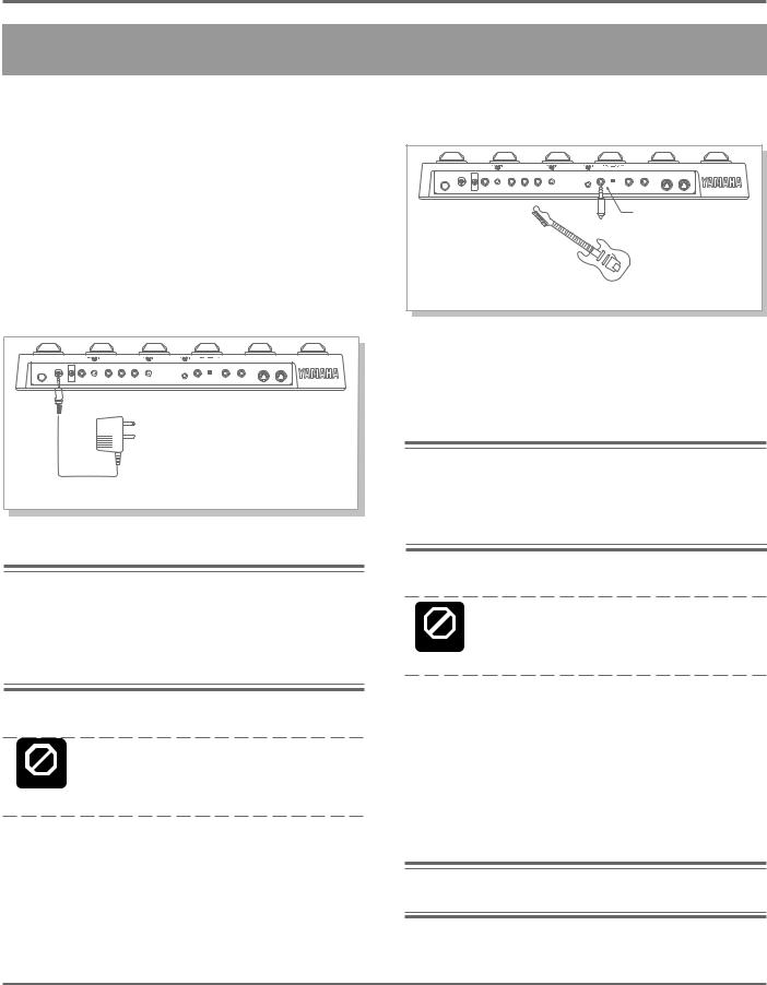
1. First, make sure that the power switch on the GW50 is off before making ANY connections.
2. Plug the DC output cable from the supplied PA-3 adaptor into the DC IN terminal on the rear panel, then plug the adaptor into a convenient AC outlet.
DC IN Cable clip (see page 15).
Note: Be sure to check whether the rated voltage is appropriate. The provided adaptor is intended for use in the area which you purchased the GW50. If you intend to use it in a different area, consult your Yamaha dealer for more information on voltage requirements.
Do not attempt to use a different AC adaptor with the GW50. The use of an incompat- CAUTION ible adaptor may cause irreparable damage to the unit and pose a serious shock hazard.
3. Plug your instrument into the INPUT jack on the rear panel.
INPUT |
For the sake of these instructions, we’ll assume you’re using an electric guitar; however, most any electronic instrument can be used.
Note: You should be careful if you are connecting a synthesizer or electronic keyboard; generally their output level is much higher than that of a guitar and the input level (see step #6 below) should be turned down accordingly.
Do not connect the BACKING/MONO output jack with the INPUT jack in an attempt to CAUTION use the effects of the GW50 on the Backing
sound. Doing so results in feedback.
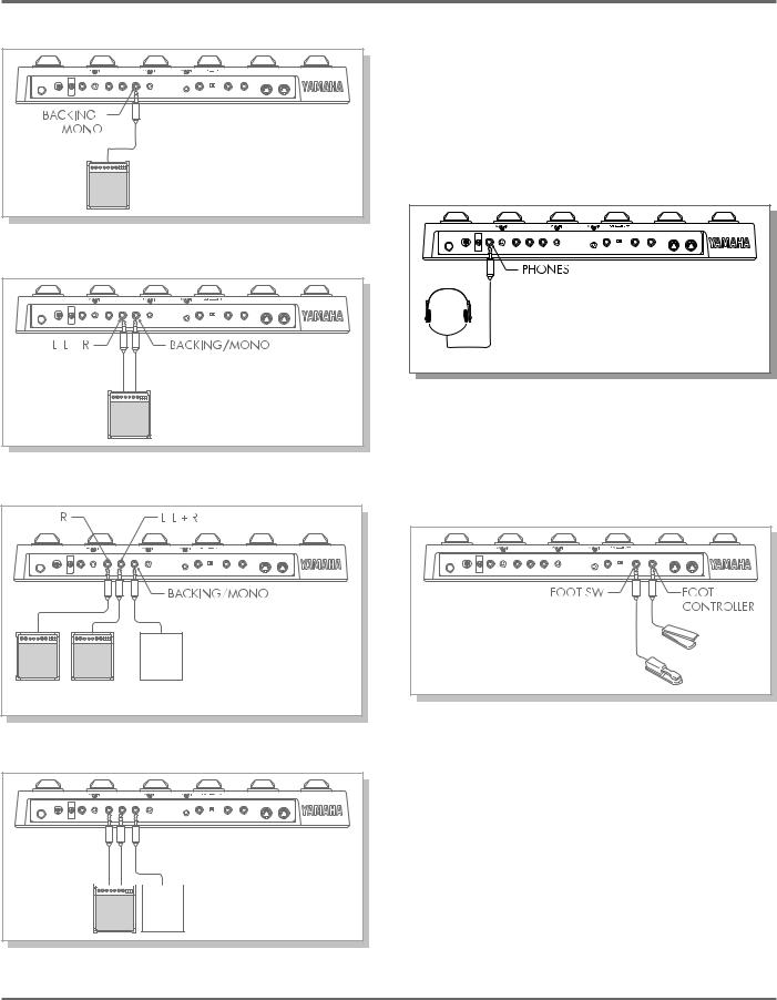
4. Connect the GW50 outputs to your amplifier/ speaker system, making sure that the power on the system is first turned off.
Four example connection systems are shown below. Use the one which most closely resembles your own system.
Note:When using Distortion on the GW50, use the clean channel of the guitar amp.
SETTING UP AND PLAYING YOUR GW50 19
GUIDED TOUR (TUTORIAL)
Example 1 — One Input
In this system, a guitar amp with only one input is used. Since the Backing sound and instrument/effect sound are output together, adjust the balance between the two with the rear panel BACKING LEVEL control.
Example 2 — Two Inputs
In this system, a guitar amp with two inputs is used. The balance between the instrument/effect output and the Backing sound can be adjusted on the amp.
Example 3 — Guitar Amp(s) and Stereo System
In examples 2, 3 and 4 above, only the Backing parts (rhythm, accompaniment, etc.) are output from the BACKING/MONO jack and only the instrument/effect sound is output from the L/L + R jack or the L/L + R and R jacks.
You can also listen to the GW50 through a set of headphones. Connect them to the PHONES jack on the rear panel.
5. If you have them, connect a foot controller (the optional Yamaha FC7) to the FOOT CONTROLLER jack, and a footswitch (the optional Yamaha FC5 or FC4) to the FOOT SW jack.
|
Here, a stereo system is used |
Stereo |
for only the Backing sound, |
while the instrument/effect |
|
System |
sound goes into one or two |
Use this (the L/L + R) jack |
guitar amps. |
|
|
if only one amp is available. |
|
Example 4 — Mixing Console
This set up is best used with the
Amp Simulator effect.
In this system for studio recording applications, the Backing sound


 only goes into one channel of a
mixer, while the left and right
Mixing channels of the instrument/effect Console sound go into separate mixer
channels.
This step isn’t necessary for using your GW50 for the first time; however, you may wish later to take advantage of some of the external foot controller and footswitch functions. (See pages 46, 56 for more information.)
6. Make sure that all volume settings are at the minimum: the guitar controls, the INPUT LEVEL and BACKING LEVEL on the GW50 (and the PHONES LEVEL, if you’re using headphones), and the volume on the amp.
20 SETTING UP AND PLAYING YOUR GW50
GUIDED TOUR (TUTORIAL)
Note: To set the controls on the GW50 to minimum, turn them all the way counterclockwise.
7. Turn on the power of all the equipment, starting with the GW50, then the connected amplifier.
*Adjust the LCD SETTING switch on the rear panel to set the LCD for proper viewing. Set it to FLOOR when you are using the GW50 on the floor, and to DESKTOP when you have it set on a table or desk in front of you.
8.Before turning up the volume and trying to play, set all effects to off.
To do this, press [MANUAL] (even if the [MANUAL] LED is lit) …
9. While playing your guitar, slowly bring up the volume controls to suitable levels — starting with the amp, then the guitar output.
Finally, adjust the input level control on the rear panel. Increase the level slowly as you play the guitar while looking at the INPUT PEAK indicator on the panel. The indicator should flash only slightly when you play the guitar at its loudest.
Also, check that the guitar sound doesn’t have distortion at its loudest.
10. Do the same with the BACKING LEVEL.
First turn the backing on by pressing
[START/STOP]…
…then, if any effect block LED is lit, press Pedal Switches 1–5 to turn all effects off (all effect block LEDs should be off).
off |
press these |
…then turn up the BACKING LEVEL to a suitable volume.
If you’ve followed all these instructions carefully, you should be able to hear both your guitar sound processed by the effects, and the sound of the backing parts.
Note: To stop the backing, press [START/STOP] again.
SETTING UP AND PLAYING YOUR GW50 21
 Loading...