


HTR-2064
Table of contents
 Loading...
HOME THEATER PACKAGE
YHT-196
RECEIVER /
SPEAKERS
HTR-2064 /
NS-B20/NS-C20/NS-SWP20
SERVICE MANUAL
The YHT-196 consists of the HTR-2064, NS-B20, NS-C20 and NS-SWP20.
Note:
• When the following parts are replaced, the destination MUST be written to the back-up IC (EEPROM: IC222 on
DIGITAL P.C.B.) to have proper operation. (For details, refer to No. 22 SOFT SWITCH menu of the self-diagnostic
function.)
DIGITAL P.C.B.
EEPROM: IC222 on DIGITAL P.C.B.
• When the power amplifier IC (IC 1 or IC 2 on MAIN P.C.B.) requires to be replaced, be sure to refer to “POWER
AMPLIFIER IC REPLACEMENT” before its replacement.
IMPORTANT NOTICE
This manual has been provided for the use of authorized YAMAHA Retailers and their service personnel.
It has been assumed that basic service procedures inherent to the industry, and more specifi cally YAMAHA Products, are already known
and understood by the users, and have therefore not been restated.
WARNING:
IMPORTANT:
The data provided is believed to be accurate and applicable to the unit(s) indicated on the cover. The research, engineering, and service
departments of YAMAHA are continually striving to improve YAMAHA products. Modifications are, therefore, inevitable and
specifi cations are subject to change without notice or obligation to retrofi t. Should any discrepancy appear to exist, please contact the
distributor's Service Division.
WARNING:
IMPORTANT:
Failure to follow appropriate service and safety procedures when servicing this product may result in personal injury,
destruction of expensive components, and failure of the product to perform as specifi ed. For these reasons, we advise
all YAMAHA product owners that any service required should be performed by an authorized YAMAHA Retailer or
the appointed service representative.
The presentation or sale of this manual to any individual or fi rm does not constitute authorization, certifi cation or
recognition of any applicable technical capabilities, or establish a principle-agent relationship of any form.
Static discharges can destroy expensive components. Discharge any static electricity your body may have
accumulated by grounding yourself to the ground buss in the unit (heavy gauge black wires connect to this buss).
Turn the unit OFF during disassembly and part replacement. Recheck all work before you apply power to the unit.
NS-C20/NS-SWP20
HTR-2064/NS-B20/
■ CONTENTS
TO SERVICE PERSONNEL ............................................ 2
SYSTEM COMPOSITION ................................................3
FRONT PANELS .........................................................3–4
REAR PANELS ........................................................... 5–7
REMOTE CONTROL PANEL .......................................... 8
SPECIFICATIONS ..................................................... 8–14
INTERNAL VIEW .......................................................... 15
SERVICE PRECAUTIONS ............................................ 15
POWERAMPLIFIER IC REPLACEMENT ............... 16–17
DISASSEMBLY PROCEDURES ............................. 18–20
UPDATING FIRMWARE ..........................................21–23
101227
Copyright © 2011 All rights reserved.
This manual is copyrighted by YAMAHA and may not be copied or
redistributed either in print or electronically without permission.
SELF-DIAGNOSTIC FUNCTION ...........................24–46
DISPLAY DATA ....................................................... 47–48
IC DATA ................................................................... 49–60
PIN CONNECTION DIAGRAMS .............................61–62
BLOCK DIAGRAM ........................................................63
PRINTED CIRCUIT BOARDS ................................. 64–76
SCHEMATIC DIAGRAMS .......................................77–84
REPLACEMENT PARTS LIST ................................ 85–92
REMOTE CONTROL ...............................................93–94
ADVANCED SETUP ...................................................... 95
P.O.Bo 1, Hamamatsu, apan
'11.12

HTR-2064/NS-B20/NS-C20/NS-SWP20
■ TO SERVICE PERSONNEL
1. Critical Components Information
Components having special characteristics are marked ⚠ and
must be replaced with parts having specifications equal to those
originally installed.
2. Leakage Current Measurement (For 120V Models Only)
When service has been completed, it is imperative to verify
that all exposed conductive surfaces are properly insulated
from supply circuits.
• Meter impedance should be equivalent to 1500 ohms shunted
by 0.15 F.
For U model
“CAUTION”
“F1501: FOR CONTINUED PROTECTION AGAINST RISK OF FIRE, REPLACE ONLY WITH SAME TYPE 6A,
125V FUSE.”
For C model
CAUTION
F1501: REPLACE WITH SAME TYPE 6A, 125V FUSE.
ATTENTION
F1501: UTILISER UN FUSIBLE DE RECHANGE DE MÉME TYPE DE 6A, 125V.
WALL
OUTLET
• Leakage current must not exceed 0.5mA.
• Be sure to test for leakage with the AC plug in both polarities.
EQUIPMENT
UNDER TEST
INSULATING
TABLE
AC LEAKAGE
TESTER OR
EQUIVALENT
WARNING: CHEMICAL CONTENT NOTICE!
This product contains chemicals known to the State of California to cause cancer, or birth defects or other reproductive
harm.
DO NOT PLACE SOLDER, ELECTRICAL/ELECTRONIC OR PLASTIC COMPONENTS IN YOUR MOUTH FOR ANY REASON
WHATSOEVER!
Avoid prolonged, unprotected contact between solder and your skin! When soldering, do not inhale solder fumes or
expose eyes to solder/flux vapor!
If you come in contact with solder or components located inside the enclosure of this product, wash your hands before
handling food.
HTR-2064/NS-B20/
NS-C20/NS-SWP20
About lead free solder
All of the P.C.B.s installed in this unit and solder joints are soldered using the lead free solder.
Among some types of lead free solder currently available, it is recommended to use one of the following types for the
repair work.
• Sn + Ag + Cu (tin + silver + copper)
• Sn + Cu (tin + copper)
• Sn + Zn + Bi (tin + zinc + bismuth)
Caution:
As the melting point temperature of the lead free solder is about 30°C to 40°C (50°F to 70°F) higher than that of the lead
solder, be sure to use a soldering iron suitable to each solder.
2
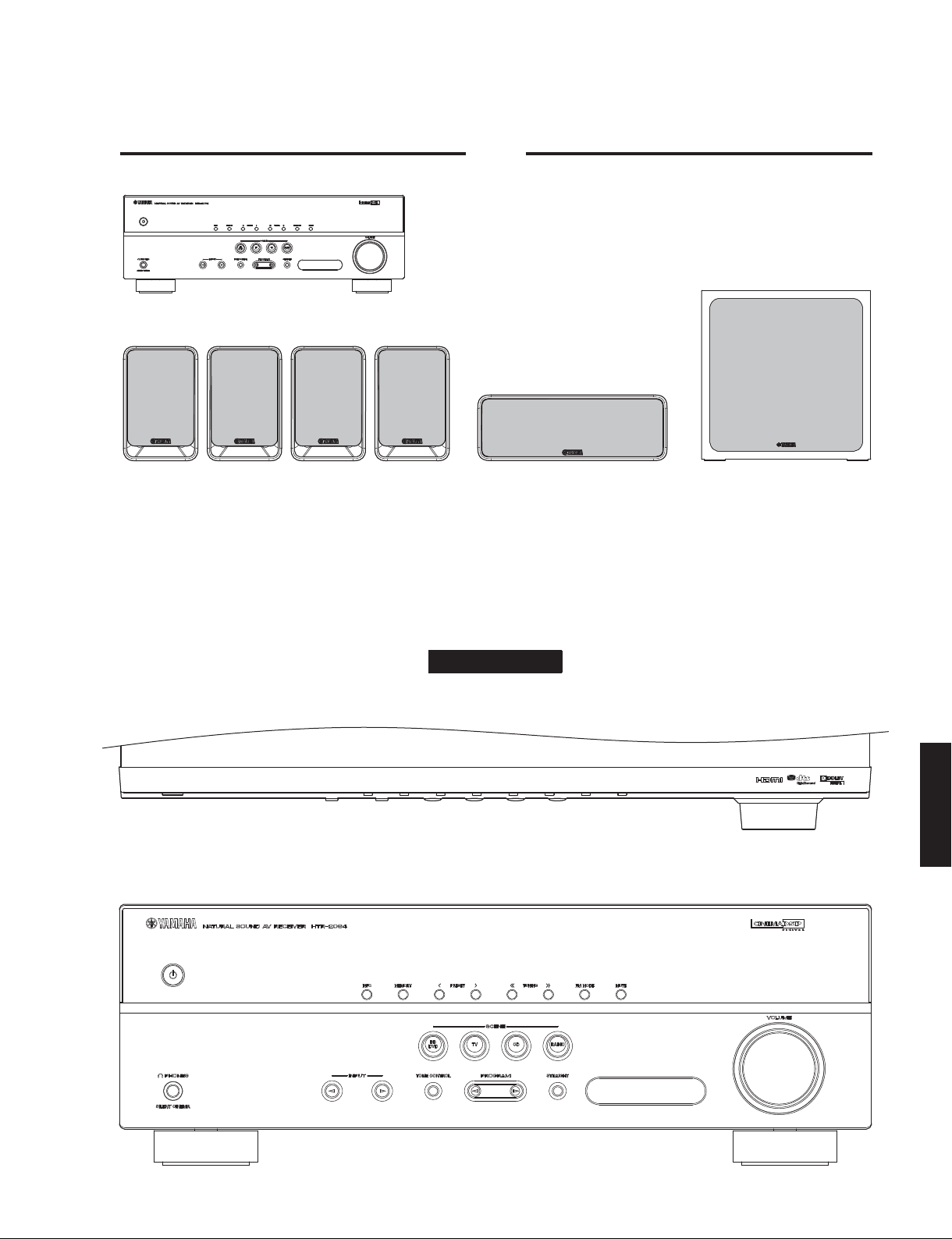
■ SYSTEM COMPOSITION
The YHT-196 consists of the HTR-2064, NS-B20 x4, NS-C20 x1 and NS-SWP20 x1.
YHT-196
HTR-2064 x 1
NS-B20 x 4
NS-C20 x 1
HTR-2064/NS-B20/NS-C20/NS-SWP20
NS-SWP20 x 1
■ FRONT PANELS
Top view
Front view
(U, C, R, A, B, G, F, L models)
(U, C, R, A, B, G, F, L models)
HTR-2064
NS-C20/NS-SWP20
HTR-2064/NS-B20/
3
HTR-2064/NS-B20/NS-C20/NS-SWP20
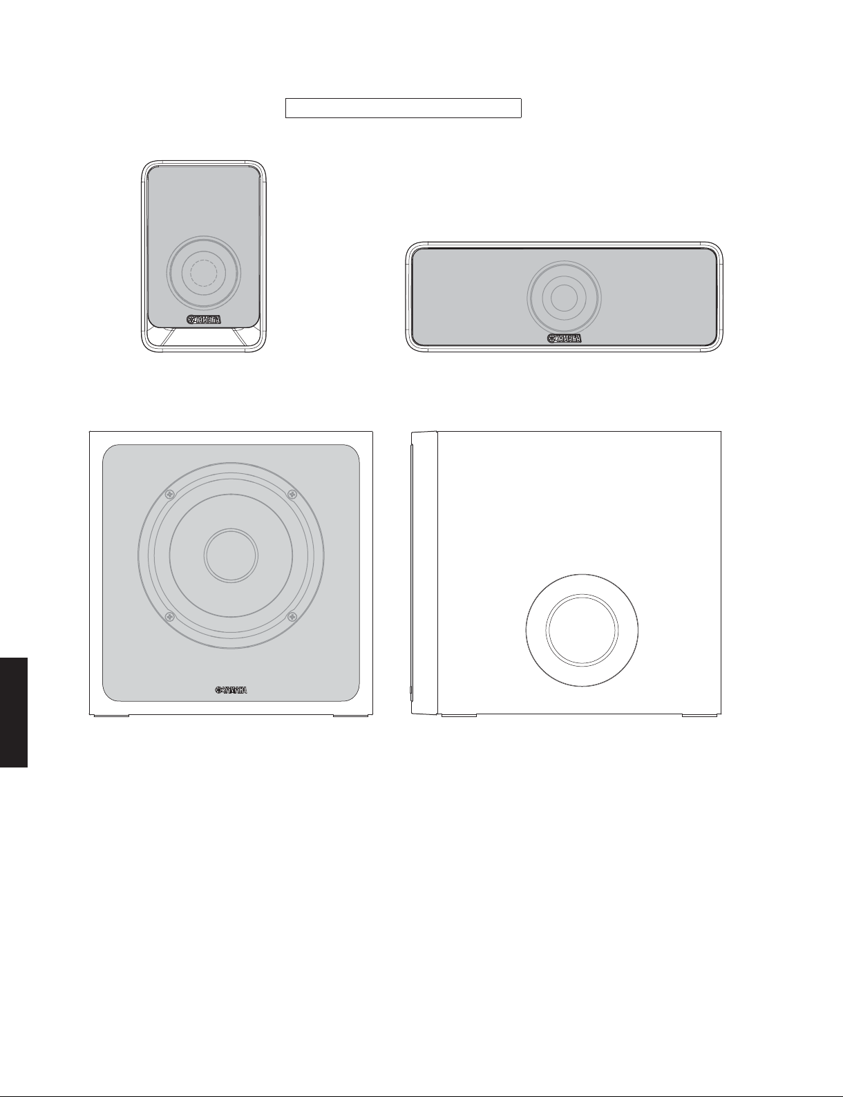
NS-B20
NS-SWP20
Front view
NS-B20/NS-C20/NS-SWP20
NS-C20
Side view
HTR-2064/NS-B20/
NS-C20/NS-SWP20
4

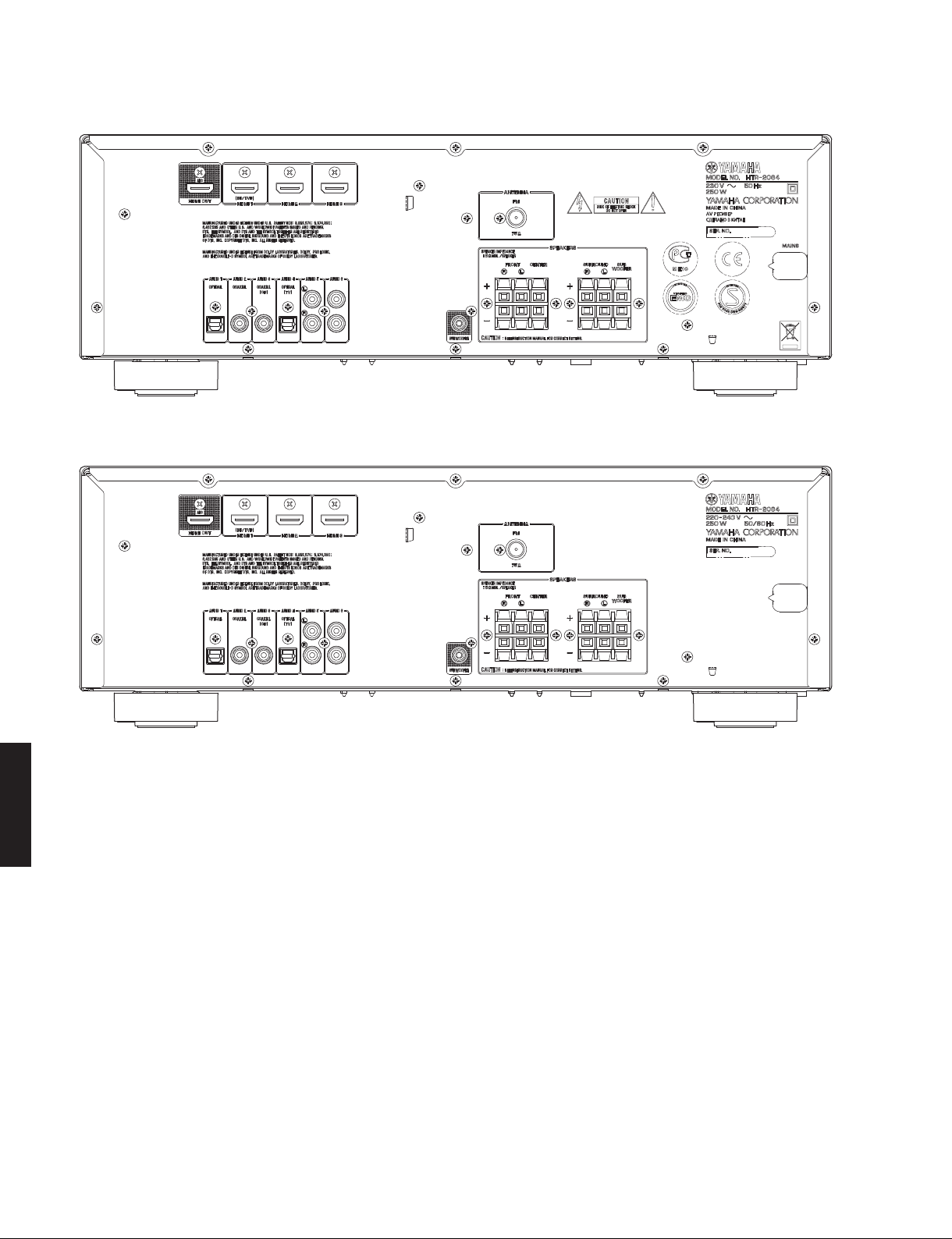
■ REAR PANELS
U, C models
HTR-2064/NS-B20/NS-C20/NS-SWP20
HTR-2064
R model
A model
NS-C20/NS-SWP20
HTR-2064/NS-B20/
5
HTR-2064/NS-B20/NS-C20/NS-SWP20
B, G, F models
L model
HTR-2064/NS-B20/
NS-C20/NS-SWP20
6
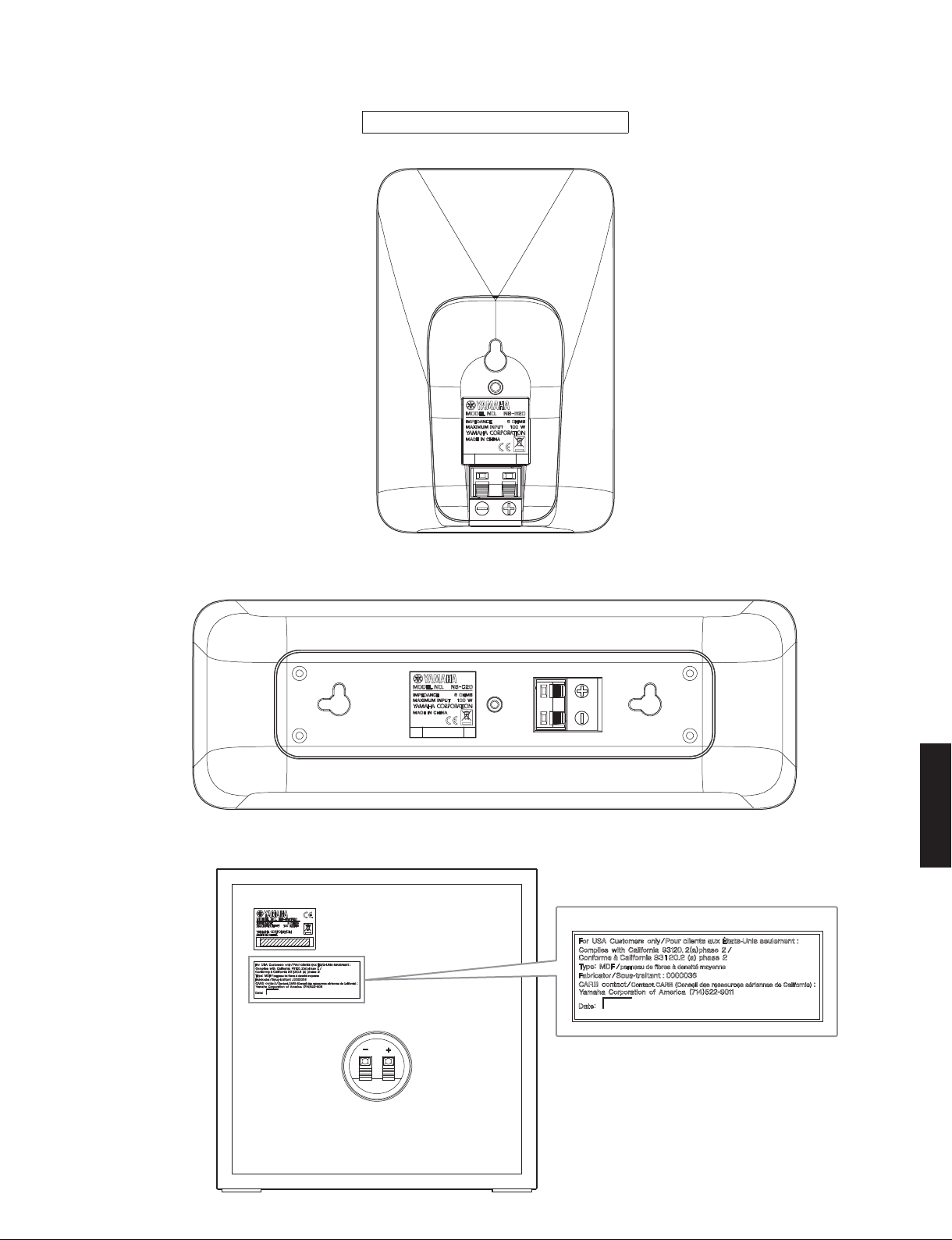
NS-B20
HTR-2064/NS-B20/NS-C20/NS-SWP20
NS-B20/NS-C20/NS-SWP20
NS-C20
NS-SWP20
U model
NS-C20/NS-SWP20
HTR-2064/NS-B20/
7
HTR-2064/NS-B20/NS-C20/NS-SWP20
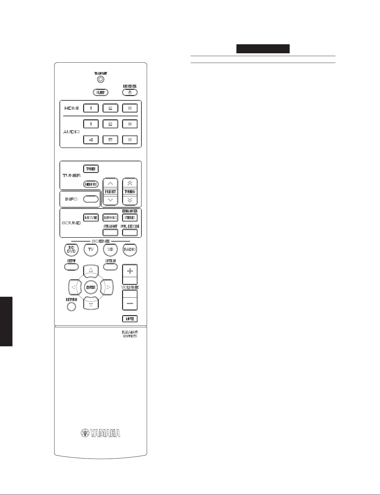
■ REMOTE CONTROL PANEL
RAV435
(U, C, R, A, B, G, F, L models)
■ SPECIFICATIONS
HTR-2064
■ Audio Section
Rated Output Power (0.9 % THD, 6 ohms)
– 2 channel driven – (U, C models)
FRONT L/R (1 kHz) ........................................80 W + 80 W
CENTER (1 kHz) ........................................................ 80 W
SURROUND L/R (1 kHz) ................................80 W + 80 W
SUBWOOFER (50 Hz) ...............................................80 W
– 1 channel driven –
FRONT L/R (1 kHz) ............................................. 100 W/ch
CENTER (1 kHz) ...................................................... 100 W
SURROUND L/R (1 kHz) ..................................... 100 W/ch
SUBWOOFER (50 Hz) .............................................100 W
Maximum Effective Output Power (1 channel driven, JEITA)
(10 % THD, 6 ohms) [R, L models]
FRONT L/R (1 kHz) ......................................135 W + 135 W
CENTER (1 kHz) ......................................................... 135 W
SURROUND L/R (1 kHz) ..............................135 W + 135 W
SUBWOOFER (50 Hz) ................................................ 135 W
Dynamic Power Per Channel (1 channel driven, IHF)
FRONT L/R
U, C models
6/4/2 ohms ............................................... 130/160/180 W
R, A, B, G, F, L models
6/4/2 ohms ............................................... 105/130/150 W
HTR-2064/NS-B20/
NS-C20/NS-SWP20
Dynamic Headroom [U, C models]
6 ohms .....................................................................0.23 dB
Input Sensitivity/Input Impedance (1 kHz, 100 W / 6 ohms)
AUDIO5, etc. ........................................ 200 mV / 47 k-ohms
Maximum Input Signal (1 kHz, 0.5 % THD, Effect on)
AUDIO5, etc. ................................................................ 2.3 V
Output Level/Output Impedance
SUBWOOFER (2 ch STEREO and FRONT speaker: Small)
................................................................. 1 V / 1.2 k-ohms
Headphone Jack Rated Output/Impedance (1 kHz, 50 mV)
AUDIO5, etc. input ................................ 100 mV / 470 ohms
Frequency Response (10 Hz to 100 kHz)
AUDIO5, etc. to FRONT L/R .................................0 / -3.0 dB
Total Harmonic Distortion (1 kHz, 50 W, 6 ohms)
AUDIO5, etc. (straight) to FRONT speaker out
.....................................................................0.06 % or less
Signal to Noise Ratio (IHF-A Network)
AUDIO5, etc. (STEREO)
Input shorted (250 mV) to speaker out ....... 98 dB or more
Residual Noise (IHF-A Network)
FRONT L/R to speaker out ..............................150 µV or less
Channel Separation
AUDIO5, etc. (Input 5.1 k-ohms shorted, 1 kHz / 10 kHz)
.......................................... 60 dB or more / 45 dB or more
Volume Control
............................ MUTE / -80 dB to +16.5 dB / 0.5 dB step
8

HTR-2064/NS-B20/NS-C20/NS-SWP20
Tone Control Characteristics * FRONT L/R channel only
BASS
Boost/Cut ............................... ±6 dB / 0.5 dB step / 50 Hz
Turnover frequency ................................................. 350 Hz
TREBLE
Boost/Cut ..............................±6 dB / 0.5 dB step / 20 kHz
Turnover frequency ................................................ 3.5 kHz
Filter Characteristics
FRONT, CENTER, SURROUND (H.P.F.)
........fc=40/60/80/90/100/110/120/160/200 Hz, 12 dB/oct.
SUBWOOFER (L.P.F.)
........fc=40/60/80/90/100/110/120/160/200 Hz, 24 dB/oct.
■ FM Section
Tuning Range
U, C models ............................................ 87.5 to 107.9 MHz
R, L models ................. 87.5 to 108.0 / 87.50 to 108.00 MHz
A, B, G, F models ................................87.50 to 108.00 MHz
50 dB Quieting Sensitivity (IHF) (1 kHz, 100 % Mod.)
Mono ............................................................ 3 µV (20.8 dBf)
Signal to Noise Ratio (IHF)
Mono / Stereo ................................................. 72 dB / 70 dB
Harmonic Distortion (1 kHz)
Mono / Stereo ..................................................0.3 % / 0.5 %
Dimensions (W x H x D)
........................ 435 x 151 x 315 mm (17-1/8" x 6" x 12-3/8")
Weight
.................................................................. 7.3 kg (16.1 lbs.)
Finish
U, C, R, A, B, G, F, L models .............................. Black color
Accessories
Remote control .................................................................x 1
Batteries (R03, AAA, UM-4) ...............................................x 2
FM antenna (1.4 m) ..........................................................x 1
* Specifications are subject to change without notice.
Manufactured under license from Dolby Laboratories. “Dolby,” “Pro Logic,”
and the double-D symbol are trademarks of Dolby Laboratories.
DTS, the Symbol, & DTS and the Symbol together are registered trademarks
& DTS Digital Surround and the DTS logos are trademarks of DTS, Inc.
Antenna Input
............................................................ 75 ohms unbalanced
■ General
Power Supply
U, C models ............................................... AC 120 V, 60 Hz
R model ...........................AC 110–120/220–240 V, 50/60 Hz
A model ...................................................... AC 240 V, 50 Hz
B, G, F models ........................................... AC 230 V, 50 Hz
L model ......................................... AC 220–240 V, 50/60 Hz
Power Consumption
U, C models .................................................250 W / 320 VA
R, A, B, G, F, L models ............................................... 250 W
Standby Power Consumption
U, C, A, B, G, F, L models ................................0.5 W or less
R model ............................................................1.0 W or less
Maximum Power Consumption
................................................................................... 440 W
“HDMI”, the “HDMI” logo and “High-Definition Multimedia Interface” are
trademarks, or registered trademarks of HDMI Licensing LLC.
“SILENT CINEMA” is a trademark of Yamaha Corporation.
NS-C20/NS-SWP20
HTR-2064/NS-B20/
9
HTR-2064/NS-B20/NS-C20/NS-SWP20
NS-B20/NS-C20/NS-SWP20
■ NS-B20/NS-C20
Type ......Full-range acoustic suspension speaker system
Non-magnetic shielding type
Driver
Full-range ........................... 7 cm (2-3/4") cone type x 1
Frequency Response
[NS-B20] ................................70 Hz to 25 kHz (-10 dB)
to 45 kHz (-30 dB)
[NS-C20] ................................65 Hz to 25 kHz (-10 dB)
to 45 kHz (-30 dB)
Impedance .............................................................6 ohms
Nominal Input .......................................................... 30 W
Maximum Input ...................................................... 100 W
Sensitivity
[NS-B20] ................................................ 83 dB/2.83 V/m
[NS-C20] ................................................ 84 dB/2.83 V/m
Input Terminal ...................................................Push type
Dimensions (W x H x D)
[NS-B20] ...........................115 mm x 176 mm x 88 mm
(4-1/2" x 6-7/8" x 3-1/2")
[NS-C20] ......................... 291 mm x 101 mm x 103 mm
(11-1/2" x 4" x 4")
Weight
[NS-B20] ............................................0.48 kg (1.06 lbs.)
[NS-C20] ............................................0.68 kg (1.50 lbs.)
■ General
Finish
U, C, R, A, B, G, F, L models .............................. Black color
Accessory
Speaker cable (25 m) ................................................x 1
Nonskid pad (NS-B20/NS-C20) ................................x 24
* Specifications are subject to change without notice.
U ........................U.S .A. model
C ..................Canadian model
R .....................General model
A .................Australian model
B .......................British model
G ..................European model
F..................... Russian model
L..................Singapore model
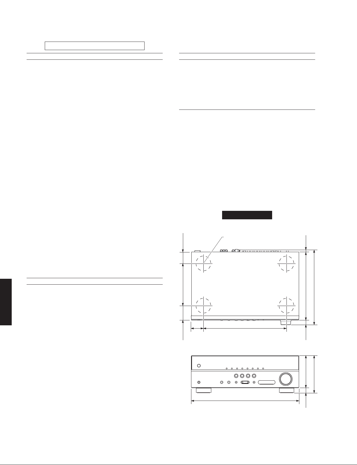
• DIMENSIONS
HTR-2064
ø 60
23
46
Top view
(1-3/4")
(7/8")
■ NS-SWP20
Type ...................................... Bass reflex speaker system
Driver
Subwoofer ........................ 16 cm (6-1/2") cone type x 1
HTR-2064/NS-B20/
NS-C20/NS-SWP20
Frequency Response ...............30 Hz to 2 kHz (-10 dB)
Impedance .............................................................6 ohms
Nominal Input .......................................................... 30 W
Maximum Input ...................................................... 100 W
Sensitivity ............................................... 86 dB/2.83 V/m
Input Terminal ...................................................Push type
Dimensions (W x H x D)
........................................262 mm x 264 mm x 287 mm
Weight ...................................................5.2 kg (11.5 lbs.)
10
Non-magnetic shielding type
to 9 kHz (-30 dB)
(10-3/8” x 10-3/8” x 11-1/4”)
170 (6-5/8")
50
58
(2")
(2-1/4")
Front view
335 (13-1/4")
435 (17-1/8")
315 (12-3/8")
274 (10-3/4")
18
(3/4")
151 (6")
130 (5-1/8")
21
(7/8")
Unit: mm (inch)
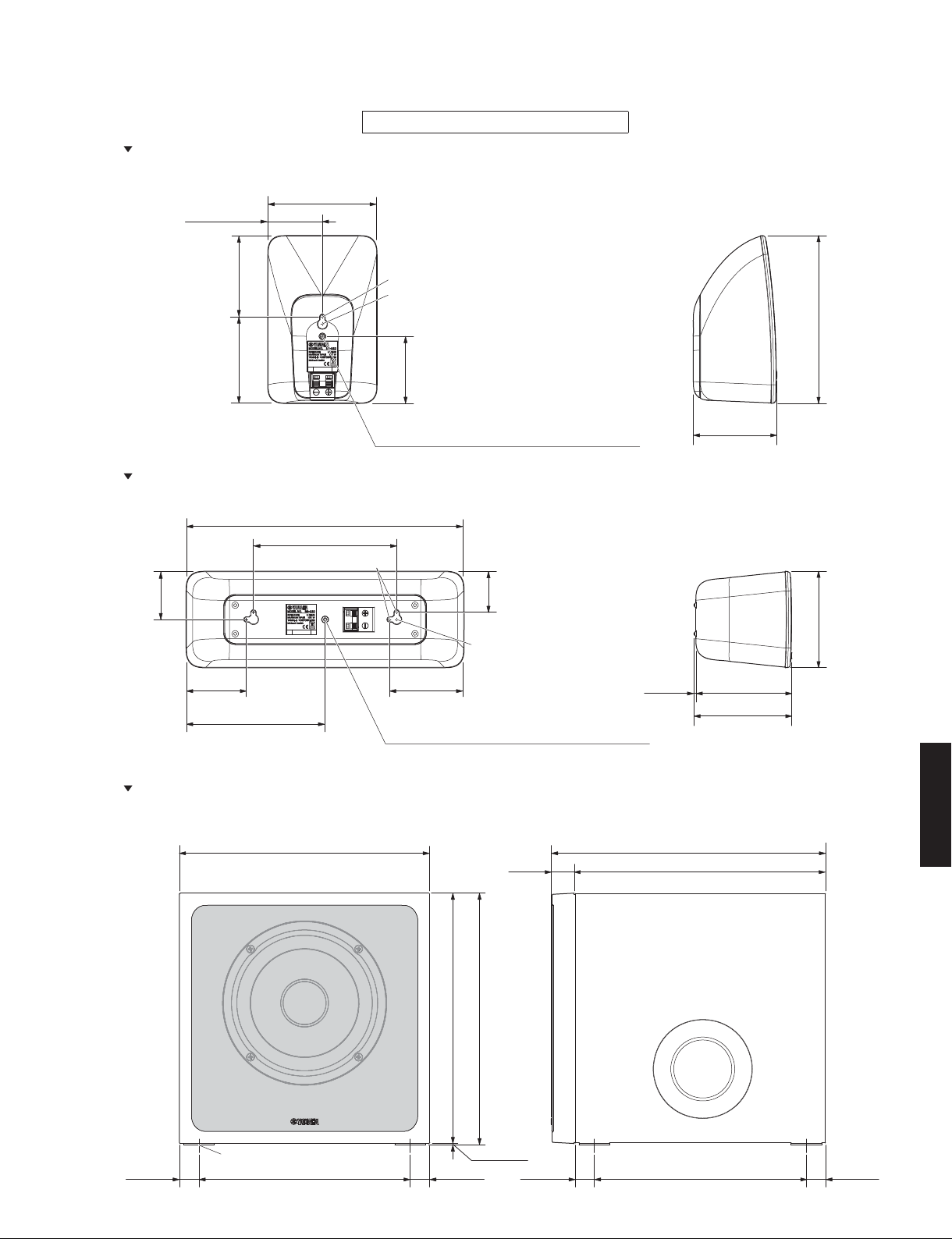
NS-B20
57.5 (2-1/4")
85.7 (3-3/8")90 (3-1/2")
HTR-2064/NS-B20/NS-C20/NS-SWP20
NS-B20/NS-C20/NS-SWP20
Unit: mm (inch)
Rear view
115 (4-1/2")
Side view
ø 5 (1/4")
ø 10 (3/8")
176 (6-7/8")101 (4")
70
(2-3/4")
A screw with a diameter of 5 mm can be used.
[Hole depth: 12 mm (1/2")]
NS-C20
Rear view
291 (11-1/2")
150 (5-7/8")
ø 5 (1/4")
50.5
(2")
66.5
(2-5/8")
145.5 (5-3/4")
74.5 (2-7/8")
A screw with a diameter of 5 mm can be used.
[Hole depth: 12 mm (1/2")]
42.5
(1-5/8")
ø 10 (3/8")
NS-SWP20
Front view Side view
262 (10-3/8") 287 (11-1/4")
262 (10-3/8")25 (1")
88 (3-1/2")
Side view
100 (3-7/8")3 (1/8")
103 (4")
NS-C20/NS-SWP20
HTR-2064/NS-B20/
20 (3/4")
ø 32 (1-1/4")
221 (8-3/4")
264 (10-3/8")
262 (10-3/8")
1.5 (1/16")
20 (3/4")
20 (3/4")
221 (8-3/4")
20 (3/4")
11
HTR-2064/NS-B20/NS-C20/NS-SWP20
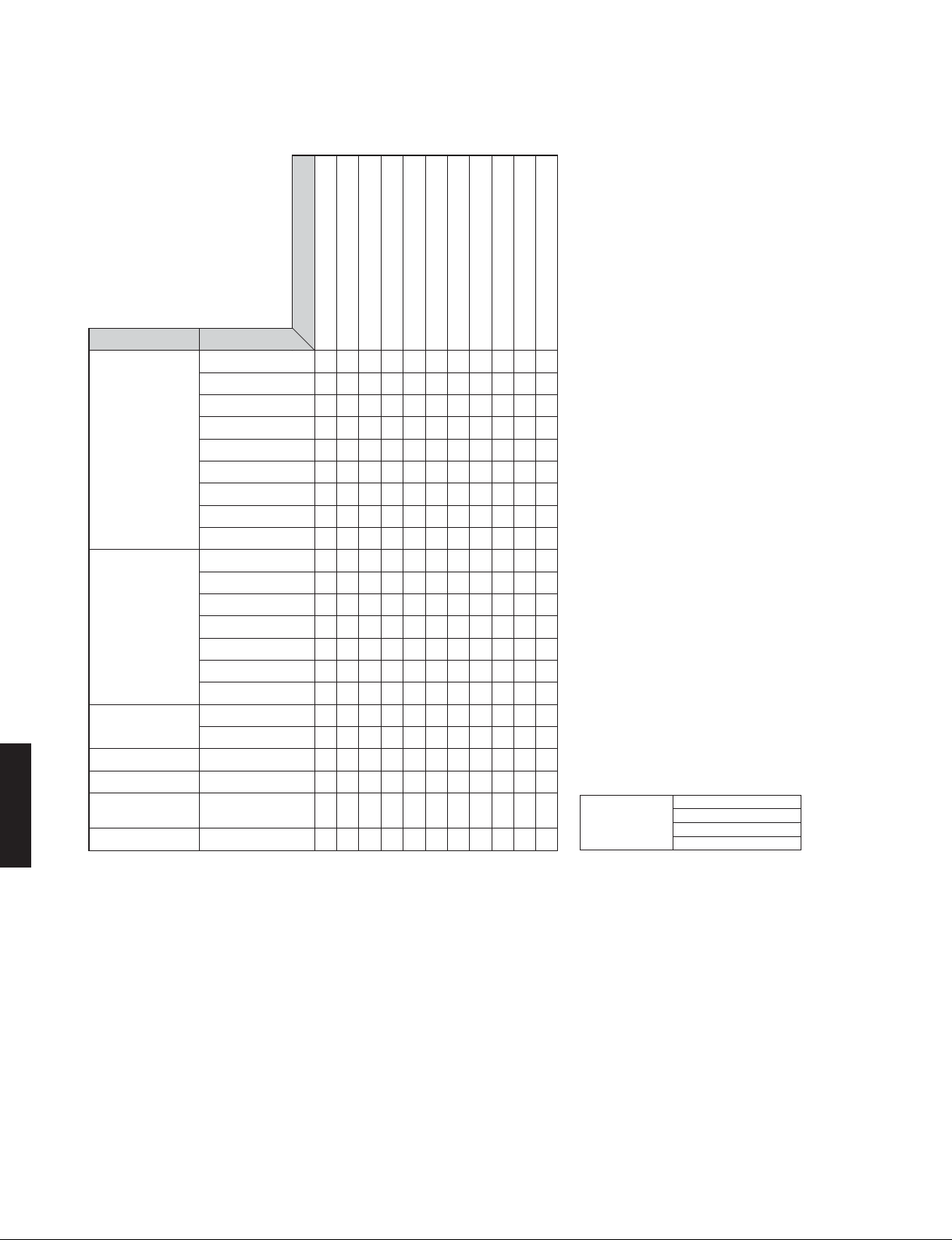
• SELECT MENU Sound field parameters
Parameter
MOVIE
MUSIC
STEREO
MUSIC ENHANCER
SUR. DECODE SUR. DECODE
STRAIGHT
HTR-2064/NS-B20/
NS-C20/NS-SWP20
: Setting is possible only when Pro Logic II Music is selected using decode type.
△
Category Program
Standard
Spectacle
Sci-Fi
Adventure
Drama
Mono Movie
Sports
Action Game
Roleplaying Game
Hall in Munich
Hall in Vienna
Chamber
Cellar Club
The Roxy Theatre
The Bottom Line
Music Video
2ch Stereo
5ch Stereo
Straight Enhancer
5ch Enhancer
Decode Type
DSP Level: -6dB to +3dB, [0 dB]
Center Level: 0 to 100%, [100%]
Surround L Level: 0 to 100%, [100%]
Surround R Level: 0 to 100%, [100%]
Direct: Auto/Off, [Auto]
Effect Level: High/Low, [High]
Panorama: On/Off, [Off]
Center Width: 0 to 7, [3]
Dimension: -3 to +3, [0]
Initialize
●●
●●
●●
●●
●●
●●
●●
●●
●●
●●
●●
●●
●●
●●
●●
●●
●●
●●● ●
●●
●●
●
*1
△●
*1 Decode Type
Decode Type
Dolby Pro Logic
Dolby PL II Movie
Dolby PL II Music
Dolby PL II Game
12
HTR-2064/NS-B20/NS-C20/NS-SWP20
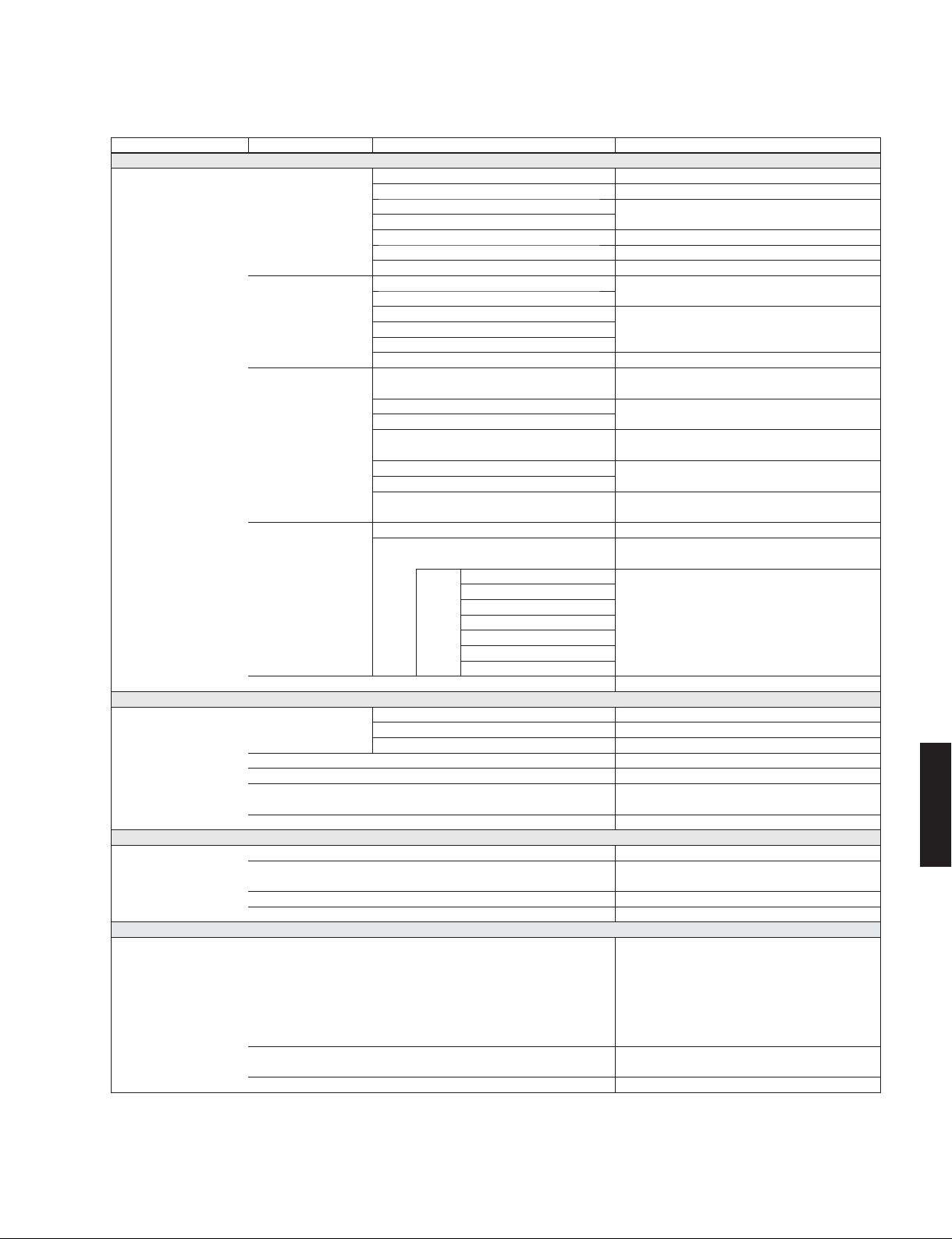
• SET MENU TABLE
MAIN MENU SUB-MENU PARAMETER VALUE [INITIAL VALUE]
1 Speaker Setup
2 Sound Setup
3 HDMI Setup
4 Function Setup
1 Config Subwoofer [Yes] / None
2 Level FL (Front speaker L)
3 Distance
4 Equalizer EQ Type Select [GEQ] / Off
5 Test Tone [Off] / On
1 Lipsync HDMI Auto Off / [On]
2 Adaptive DRC [Off] / On
3 D.Range Min / Std / [Max]
4 Max Volume -30.0 to +15.0 dB / +16.5 dB (Maximum volume),
5 Init. Volume Off, Mute, -80 dB to +16.5 dB [Off], 0.5 dB step
1 Control [Off] / On
2 TV Audio AUDIO1 / AUDIO2 / AUDIO3 / [AUDIO4] / AUDIO5 /
3 ARC Off / [On]
4 Audio [Amp] / TV / Amp+TV
1 Input Rename Input is possible to 9 characters
2 Auto Power Down U, C, R, A, L models: [Off] / 4 hours / 8 hours / 12 hours
3 Dimmer -4 to 0, [0]
Front speaker [Small] / Large
Center speaker
Surround speaker L/R
Crossover 40 / 60 / 80 / 90 / 100 / 110 / 120 / [160] / 200 Hz
Subwoofer Phase [NRM] / REV
Extra Bass [Off] / On
FR (Front speaker R)
C (Center speaker)
SR (Surround speaker R)
SWFR (Subwoofer) -10.0 to +10.0 dB, [0 dB], 0.5 dB step
Unit
Front L (Front speaker L) 0.30 to 24.00 m, [3.00 m], 0.1 m step
Front R (Front speaker R)
Center (Center speaker) 0.30 to 24.00 m, [2.60 m], 0.1 m step
Sur. L (Surround speaker L) 0.30 to 24.00 m, [2.40 m], 0.1 m step
Sur. R (Surround speaker R)
SWFR (Subwoofer) 0.30 to 24.00 m, [3.00 m], 0.1 m step
GEQ * “GEQ” is available only when “EQ Type Select” is set
Front L 63 Hz ···········||··········· 0 dB
Front R 160 Hz ···········||··········· 0 dB
Center 400 Hz ···········||··········· 0 dB
Sur. L 1 kHz ···········||··········· 0 dB
Sur. R 2.5 kHz ···········||··········· 0 dB
6.3 kHz ···········||··········· 0 dB
16 kHz ···········||··········· 0 dB
Auto 0 to 240 ms, 1 ms step
Manual 0 to 240 ms, [0 ms], 1 ms step
None / [Small] / Large
-10.0 to +10.0 dB, [0 dB], 0.5 dB step
-10.0 to +10.0 dB, [-1.0 dB], 0.5 dB stepSL (Surround speaker L)
U, C models: meters (m) / [feet (ft)]
R, A, B, G, F, L models: [meters (m)] / feet (ft)
1.0 to 80.0 ft, [10.0 ft], 0.5 ft step
1.0 to 80.0 ft, [8.5 ft], 0.5 ft step
1.0 to 80.0 ft, [8.0 ft], 0.5 ft step
1.0 to 80.0 ft, [10.0 ft], 0.5 ft step
to “GEQ”.
-6.0 to +6.0 dB, [0 dB], 0.5 dB step
[+16.5 dB], 5.0 dB step
AUDIO6
Input possible Character type
Capital : A to Z
Small : a to z
Figure : 0 to 9
Symbols : # * + , - etc.
Space
B, G, F models: Off / 4 hours / [8 hours] / 12 hours
NS-C20/NS-SWP20
HTR-2064/NS-B20/
13
HTR-2064/NS-B20/NS-C20/NS-SWP20
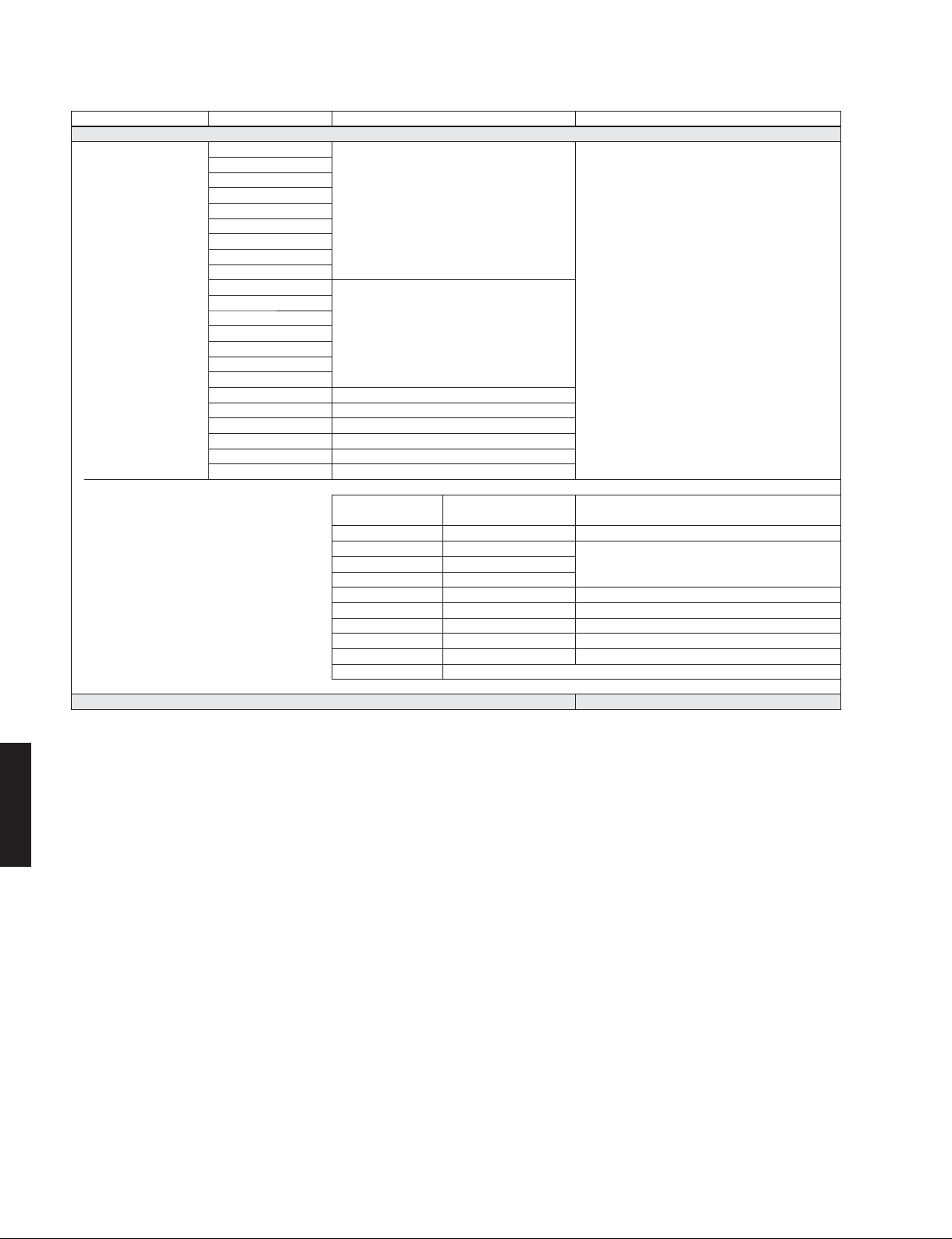
MAIN MENU SUB-MENU PARAMETER VALUE [INITIAL VALUE]
5 DSP Parameter
MUSIC ENHANCER Straight Enhancer [7], [11]
MOVIE Standard
Spectacle
Sci-Fi
Adventure
Drama
Mono Movie
Sports
Action Game
Roleplaying Game
MUSIC Hall in Munich
Hall in Vienna
Chamber
Cellar Club
The Roxy Theatre
The Bottom Line
Music Video
STEREO 2ch Stereo [6], [11]
5ch Stereo [3], [4], [5], [11]
5ch Enhancer [7], [11]
SUR. DECODE SUR. DECODE [1], [8], [11]
STRAIGHT
[2], [11]
[2], [11]
6 Memory Guard [Off] / On
HTR-2064/NS-B20/
NS-C20/NS-SWP20
[1] Decode Type
[2] DSP Level -6 to +3 dB, [0 dB]
[3] Center Level
[4] Surround L Level 0 to 100 %, [100 %]
[5] Surround R Level
[6] Direct [Auto] / Off
[7] Effect Level [High] / Low
[8] Panorama [Off] / On
[9] Center Width 0 to 7, [3]
[10] Dimension -3 to +3, [0]
[11] Initialize
Dolby Pro Logic, Dolby PL II Movie, Dolby PL II Music,
Dolby PL II Game, Neo:6 Cinema, Neo:6 Music
14

■ INTERNAL VIEW
Top view
HTR-2064/NS-B20/NS-C20/NS-SWP20
1
11
Front view
12 13 14
3524 6
10
97
1
OPERATION (3) P.C.B.
2
MAIN (2) P.C.B. (R model)
3
MAIN (1) P.C.B.
4
FM TUNER
5
DIGITAL P.C.B.
6
OPERATION (4) P.C.B.
7
MAIN (3) P.C.B.
8
OPERATION (9) P.C.B.
9
OPERATION (2) P.C.B.
10
OPERATION (8) P.C.B.
11
POWER TRANSFORMER
12
OPERATION (7) P.C.B.
13
OPERATION (1) P.C.B.
14
OPERATION (6) P.C.B.
15
OPERATION (5) P.C.B.
8
15
■ SERVICE PRECAUTIONS
Safety measures
• Some internal parts in this product contain high voltages and are dangerous.
Be sure to take safety measures during servicing, such as wearing insulating gloves.
• Note that the capacitors indicated below are dangerous even after the power is turned off because an electric charge
remains and a high voltage continues to exist there.
Before starting any repair work, connect a discharging resistor (5 k-ohms/10 W) to the terminals of each capacitor
indicated below to discharge electricity.
The time required for discharging is about 30 seconds per each.
C1318–C1320 on OPERATION (2) P.C.B.
C55, C56 on MAIN (1) P.C.B.
NS-C20/NS-SWP20
HTR-2064/NS-B20/
For details, refer to “PRINTED CIRCUIT BOARDS”.
15
HTR-2064/NS-B20/NS-C20/NS-SWP20
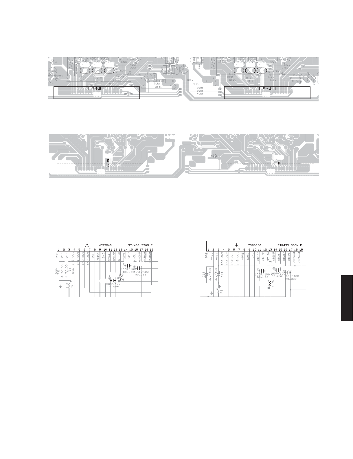
■ POWER AMPLIFIER IC REPLACEMENT
In the middle of production, the power amplifier IC has been changed from Y type to N type. At the same time, their
peripheral electrical parts also have been altered.
Y type: Parts No. X8190B00 STK433-330Y-E Initial production
N type: Parts No. YD936A00 STK433-330N-E Middle production and after
Service replacement part
Therefore, when replacing Y type with N type, their peripheral electrical parts also MUST be altered at the same time.
Replacement procedure
Perform the following procedure according to the type name of installed power amplifier IC.
Top view
Rear side
HTR-2064/NS-B20/
NS-C20/NS-SWP20
IC1
Fig. 1
Y
STK433-330
119
Fig. 2
MAIN (1) P.C.B.
IC2
Front side
When “Y” is printed
<IC1>
Remove C25, C29 and C33.
Replace R23 with 4.7 k-ohms.
Replace IC1 with N type.
<IC2>
Remove C24, C31 and C34.
Replace R25 with 4.7 k-ohms.
Replace IC2 with N type.
When “N” is printed
Replace IC1/IC2 with N type.
16
MAIN (1) P.C.B. top view
HTR-2064/NS-B20/NS-C20/NS-SWP20
C29C33
IC1 IC2
MAIN (1) P.C.B. bottom view
Schematic diagrams
IC2
R25
C24C31C34C25
R23
IC1
Fig. 3
IC1
C25
R23
C29
C33
Fig. 4
IC2
C24
R25
C31
C34
NS-C20/NS-SWP20
HTR-2064/NS-B20/
17
HTR-2064/NS-B20/NS-C20/NS-SWP20
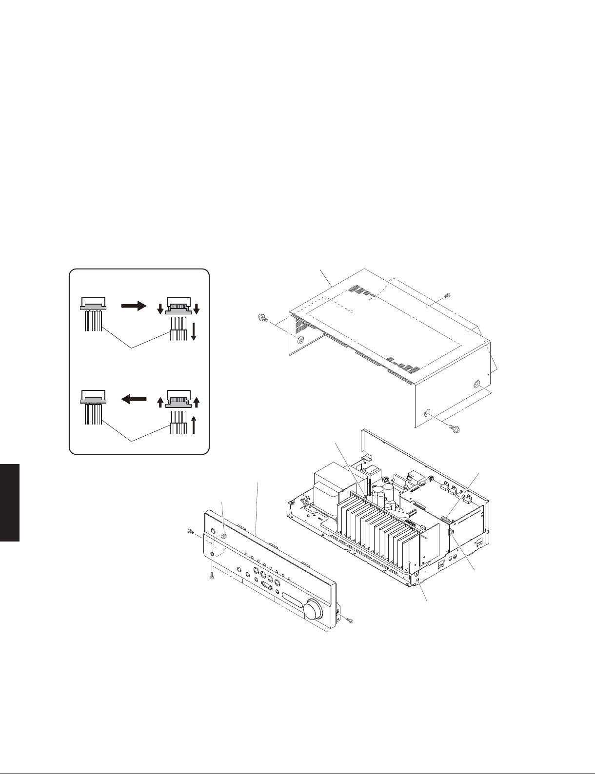
■ DISASSEMBLY PROCEDURES
(Remove parts in the order as numbered.)
Disconnect the power cable from the AC outlet.
1. Removal of Top Cover
a. Remove 5 screws (①) and 4 screws (②). (Fig. 1)
b. Slide the top cover rearward to remove it. (Fig. 1)
2. Removal of Front Panel Unit
a. Remove 7 screws (③). (Fig. 1)
b. Remove CB166, CB193 and CB221. (Fig. 1)
c. Unlock and remove CB136. (Fig. 1)
d. Release hook and then remove the front panel unit. (Fig. 1)
Remove CB136 and CB262
Connected
Unlock the connector
①
Remove the cable
②
①①
②
②
Top cover
①
HTR-2064/NS-B20/
NS-C20/NS-SWP20
Cable
Connect CB136 and CB262
Lock the connector
Connected
①
Insert the cable
②
①①
Cable
②
CB136
Front panel unit
②
CB221
CB166
③
CB193
③
Hook
③
18
Fig. 1
HTR-2064/NS-B20/NS-C20/NS-SWP20
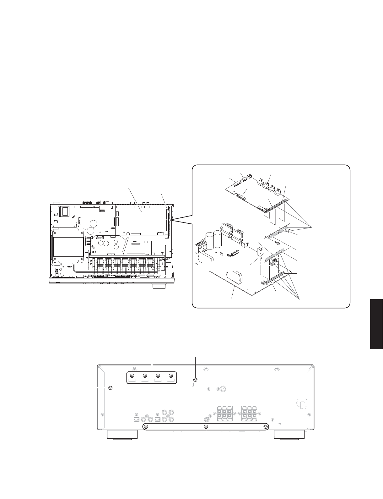
3. Removal of DIGITAL P.C.B.
a. Remove CB222 and CB223. (Fig. 2)
b. Unlock and remove CB262. (Fig. 2)
c. Remove screw (④). (Fig. 2)
d. Remove screw (⑤) and 4 screws (⑥). (Fig. 3)
e. Remove the DIGITAL P.C.B. which is connected directly to the OPERATION (4) P.C.B. with board-to-board connectors.
(Fig. 2)
4. Removal of OPERATION (4) P.C.B.
a. Remove screw (⑦). (Fig. 3)
b. Remove screw (⑧). (Fig. 2)
c. Remove the OPERATION (4) P.C.B. which is connected directly to the MAIN (1) P.C.B. with board-to-board connectors.
(Fig. 2)
DIGITAL P.C.B.
OPERATION (4) P.C.B.
CB223
CB222
OPERATION (4) P.C.B.
MAIN (1) P.C.B.
Fig. 2
CB262
CB191
DIGITAL P.C.B.
CB264
④
⑧
CB22
CB263
Board-to-board
connectors
CB196
CB195
CB192
CB21
Board-to-board
connectors
NS-C20/NS-SWP20
HTR-2064/NS-B20/
⑥
⑦
⑤
⑨
Fig. 3
19
HTR-2064/NS-B20/NS-C20/NS-SWP20
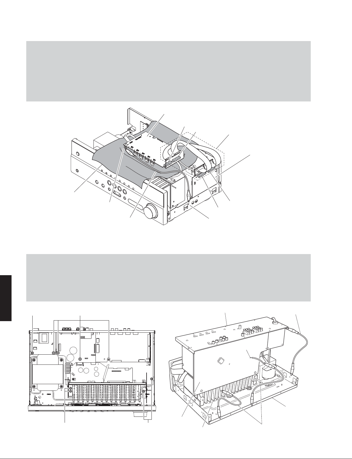
When checking the DIGITAL P.C.B.
• Put the rubber sheet and cloth over this unit, and place the DIGITAL P.C.B. on them. (Fig. 4)
• Connect ST201 on DIGITAL P.C.B. to the chassis with a ground lead or the like. (Fig. 4)
• Reconnect all cables (connectors) that have been disconnected. Be sure to use the P.C.B. CHECKING JIG (Part No.
WW483800) to connect between the following connectors.
CB263 on DIGITAL P.C.B. – CB196 on OPERATION (4) P.C.B.
CB264 on DIGITAL P.C.B. – CB195 on OPERATION (4) P.C.B.
• When connecting the flexible flat cable, be careful with polarity.
DIGITAL P.C.B.
CB263
CB264
P.C.B. CHECKING JIG
OPERATION (4) P.C.B.
When checking the MAIN (1) P.C.B.
a. Remove the top cover. (Fig. 1)
b. Remove 3 screws (⑨). (Fig. 3)
c. Remove 5 screws (⑩) and 4 screws (⑪). (Fig. 5)
d. Place the P.C.B.s (with rear panel) upright. (Fig. 6)
e. Connect the heatsink, rear panel and MAIN (1) P.C.B. (G3) to the chassis with a ground lead or the like. (Fig. 6)
HTR-2064/NS-B20/
NS-C20/NS-SWP20
Rubber sheet and cloth
⑪⑩
ST201
Ground lead
Fig. 4
CB195
Chassis
Rear panel
CB196
Ground lead
G3
20
Chassis
⑩⑩
MAIN (1) P.C.B.
Heatsink
Ground lead
Fig. 6Fig. 5

HTR-2064/NS-B20/NS-C20/NS-SWP20
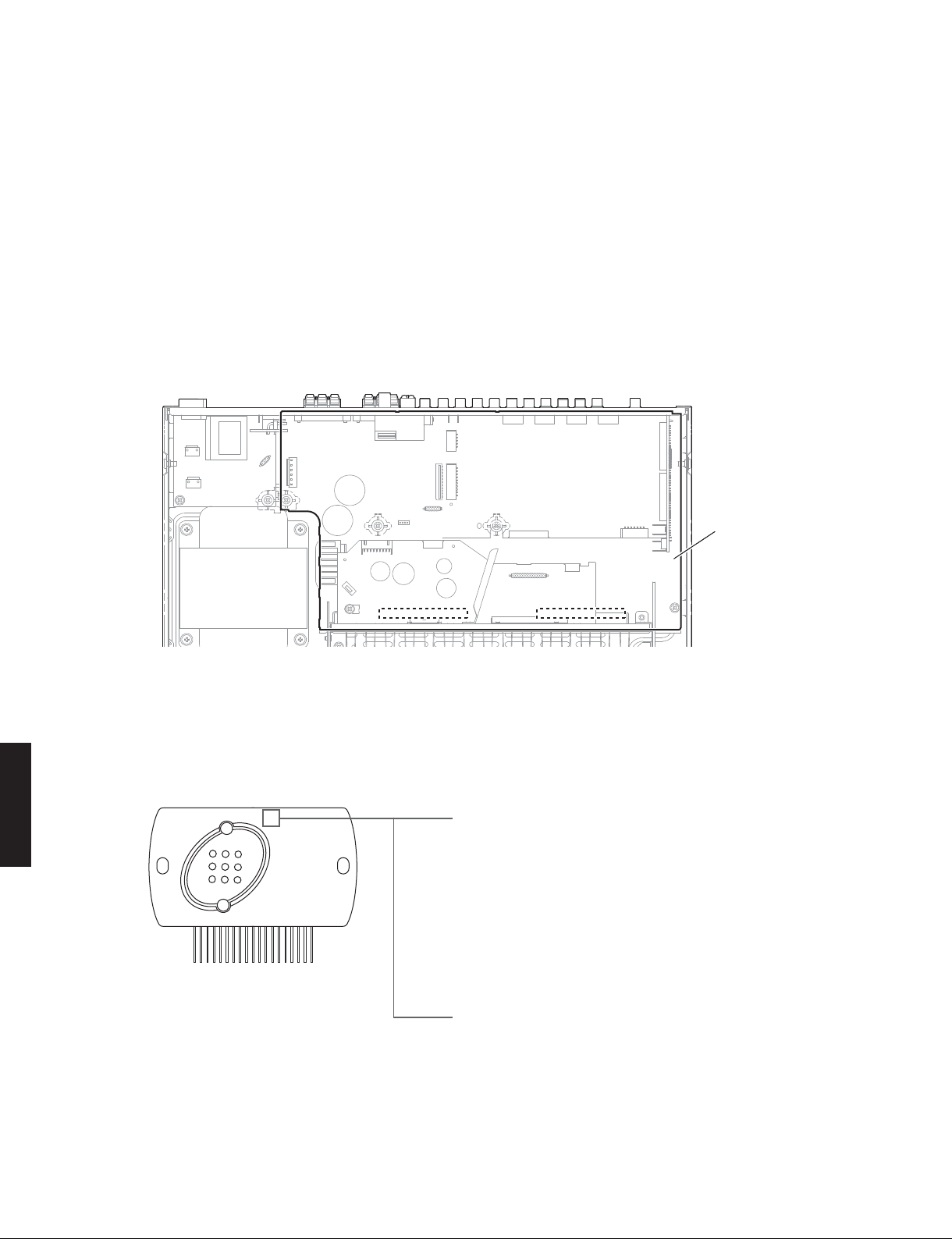
■ UPDATING FIRMWARE
When the following parts are replaced, the firmware must be updated to the latest version.
DIGITAL P.C.B.
DSP FLASH ROM (IC243 on DIGITAL P.C.B.)
● Confirmation of firmware version and checksum
Before and after updating the firmware, check the firmware version and checksum by using the self-diagnostic
function menu.
Start up the self-diagnostic function and select “25. ROM VER/SUM/PORT” menu.
Using the sub-menu, have the firmware version and checksum displayed, and note them down.
(For details, refer to “SELF-DIAGNOSTIC FUNCTION”)
* When the firmware version is different from written one after updating, perform the updating procedure from the
beginning again.
● Initializing the back-up IC (EEPROM: IC222 on DIGITAL P.C.B.)
After updating the firmware, the back-up IC MUST be initialized by the following procedure to store the setting
information (soundfield parameters, system memory and tuner presetting, etc.) properly.
Start up the self-diagnostic function and select “24. FACTORY PRESET” menu. (For details, refer to “SELF-DIAGNOSTIC
FUNCTION”)
Select “24. PRESET RSRV”, press the “
the back-up IC is initialized.
” (Power) key to turn off the power once and turn on the power again. Then
● Required Tools
• CD, DVD or BD player (with DIGITAL OUTPUT (OPTICAL or COAXIAL) jack)
* The following models can be used as a tool to update the firmware.
CD player: CD-C600/CD-S1000/CD-S2000/CD-S300/CD-S700/CDX-496/CDX-596/CDX-890
DVD player: DV-C6760/DVD-840/DVD-C740/DVD-C750/DVD-C940/DVD-C950/DVD-CX1/DVD-S1200/DVD-S1800/
DVD-S2300(MKII)/DVD-S2700/DVD-S30/DVD-S510/DVD-S520/DVD-S530/DVD-S540/DVD-S550/
DVD-S657/DVD-S700/DVD-S80/DVD-S840
BD player: BD-940/BD-S1065/BD-S1900/BD-S2900/BD-S671
Others: CDR-D651/CDR-HD1000/CDR-HD1300/CDR-HD1500/DV-SL100/CDX-E100/CRX-430/CRX-E150/
RDX-E700
• Optical cable (when OPTICAL jack is used)
• Digital audio pin cable (when COAXIAL jack is used)
NS-C20/NS-SWP20
HTR-2064/NS-B20/
• Firmware CD
Download the latest firmware from the specified download source and create the firmware CD.
21
HTR-2064/NS-B20/NS-C20/NS-SWP20
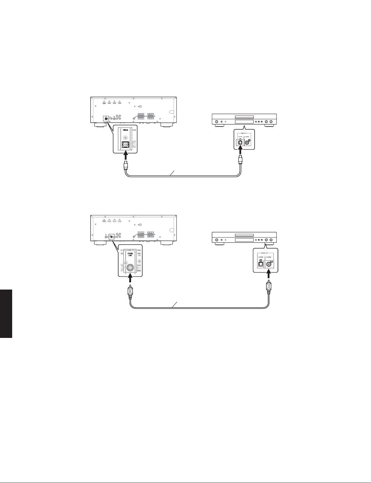
● Connection
Connect a CD/DVD/BD player to this unit as shown below. (Fig. 1)
Example of connection between digital OPTICAL jacks
This unit
CD/DVD/BD player
Optical cable
Example of connection between digital COAXIAL jacks
HTR-2064/NS-B20/
NS-C20/NS-SWP20
This unit
CD/DVD/BD player
Digital audio pin cable
Fig. 1
22
● Operation Procedures
1. While pressing the “INFO” key, connect the power cable to the AC outlet. (Fig. 2)
The FIRMWARE UPDATE mode is activated and “CDDA Upgrader” is displayed. (Fig. 2)
"INFO" key
Display
CDDAUpgrader
Fig. 2
HTR-2064/NS-B20/NS-C20/NS-SWP20
2. Play the firmware CD on the CD/DVD/BD player. Writing of the firmware starts automatically. (Fig. 3)
3. When writing of the firmware is completed, “Update Success”, “Please...” and “Power off!!” are displayed
repeatedly. (Fig. 3)
Writing is started Writing is completed
XXXXXXXXXX UpdateSuccess
XXXXXX
: Received data
Please...
Poweroff!!
Fig. 3
* If the display remains unchanged for more than 10 seconds after starting the firmware CD play procedure,
perform the firmware CD play procedure again from the beginning.
If “FILE CORRUPTED” is displayed after “Address:XXXXXX”, make sure that the data written to the firmware CD
is not corrupted and perform Steps 1 to 3 of “Operation Procedures” again.
If “Upgrade Failed” is displayed, perform “operation procedures” from the beginning again.
NS-C20/NS-SWP20
HTR-2064/NS-B20/
4. Press the “
” (Power) key to turn off the power.
5. Eject the firmware CD from the CD/DVD/BD player.
6. Start up the self-diagnostic function and check that the firmware version and checksum are the same as written
ones. (See “Confirmation of firmware version and checksum”)
23

HTR-2064/NS-B20/NS-C20/NS-SWP20
■ SELF-DIAGNOSTIC FUNCTION
This unit has self-diagnostic functions that are intended for inspection, measurement and location of faulty point.
There are 26 main menu items, each of which has sub-menu items.
Listed in the table below are main menu items and sub-menu items.
Note: Some of the menu items listed below may not apply to the models covered in this service manual.
No. Main menu Sub-menu
1 BYPASS 1 ANALOG BYPASS
2 RAM THROUGH 1 RAM MARGIN
3 HDMI AUDIO 1 SPDIF
4 SPEAKERS SET 1 FRONT: SML 0dB
5 LIMITER CONTROL (Not for service) 1 AC_B: Hi
6 NO MENU Invalidity
7 VFD CHECK 1 INITIAL DISPLAY
HTR-2064/NS-B20/
NS-C20/NS-SWP20
8 MANUAL TEST 1 TEST ALL
9 AD DATA CHECK 1 PS/DC
10 VIDEO CHECK 1 I2C
11 NO MENU Invalidity
2 RAM FULL ALL
3 RAM FULL CENTER
4 RAM FULL SURROUND
5 RAM FULL SURROUND BACK (Not for service)
6 RAM FULL SUBWOOFER
2 Multi
3 DSD
4 ARC
2 CENTER: NONE
3 LFE/BASS: FRNT
4 TONE: MAX
5 TONE: MIN
6 SPEAKER 6-ohms (Not for service)
2 AC_B: Lo
3 LIM/PLDET/THM
2 ALL SEGMENT OFF
3 ALL SEGMENT ON
4 DIMMER 50%
5 CHECK PATTERN
2 TH1/TH2
3 TH3
4 AMP/DK (Not for service)
5 K1/K2
2 DIGITAL COMPONENT (Not for service)
3 DIGITAL CVBS (Not for service)
4 DIGITAL Y/C (Not for service)
5 ANALOG BYPASS (Not for service)
24

HTR-2064/NS-B20/NS-C20/NS-SWP20
No. Main menu Sub-menu
12 NO MENU Invalidity
13 NO MENU Invalidity
14 NO MENU Invalidity
15 HDMI INFORMATION 1 MODEL NAME
2 PRODUCT ID
3 VENDOR NAME
16 HDMI SELECT 1 HDMI NONE
2 HDMI IN 1
3 HDMI IN 2
4 HDMI IN 3
17 NO MENU Invalidity
18 IF STATUS (Not for service) 1 DSP STATUS
19 BUS CHECK 1 TI BUS:
2 EEPROM:
20 NO MENU Invalidity
21 PROTECTION HISTORY 1 HISTORY 1
2 HISTORY 2
3 HISTORY 3
4 HISTORY 4
22 SOFT SWITCH 1 SWITCH MODE
2 MODEL
3 DESTINATION
23 UPDATE (Not for service) 1 TI FLASH BOOT
24 FACTORY PRESET 1 PRESET INHIBIT
2 PRESET RESERVED
25 ROM VER/SUM/PORT 1 FIRMWARE VERSION
2 ALL CHECKSUM
3 TI (DSP) FLASH ROM VERSION
4 TI (DSP) FLASH ROM CHECKSUM
5 MODEL/DESTINATION
6 Verify (Not for service)
26 MODEL/DESTINATION (Not for service) 1 MODEL/DEST
2 M/D:
NS-C20/NS-SWP20
HTR-2064/NS-B20/
25
HTR-2064/NS-B20/NS-C20/NS-SWP20
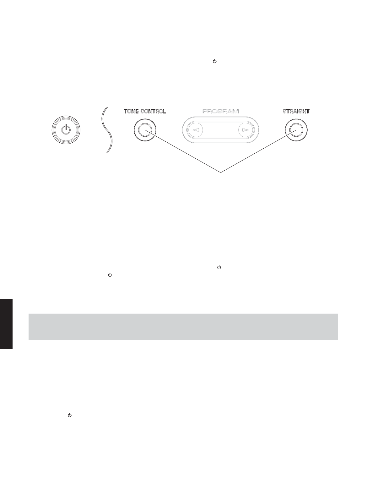
● Starting Self-Diagnostic Function
While pressing the “TONE CONTROL” and “STRAIGHT” keys, press the “ ” (Power) key to turn on the power.
The self-diagnostic function mode is activated.
Keys of this unit
(Power)
While pressing these keys, turn on the power.
● Starting Self-Diagnostic Function in the protection cancel mode
If the protection function works and causes hindrance to troubleshooting, cancel the protection function by the procedure
below, and it will be possible to enter the self-diagnostic function mode.
(The protection functions other than the excess current detect function will be disabled.)
While pressing the “TONE CONTROL” and “STRAIGHT” keys, press the “
pressing those 2 keys and the “
The self-diagnostic function mode is activated with the protection functions disabled.
In this mode, the “SLEEP” segment of the FL display flashes to indicate that the mode is self-diagnostic function mode with
the protection functions disabled.
CAUTION!
Using this unit with the protection function disabled may cause further damage to this unit. Use special care for this point
when using this mode.
HTR-2064/NS-B20/
NS-C20/NS-SWP20
● Canceling Self-Diagnostic Function
1. Before canceling self-diagnostic function, execute setting for FACTORY PRESET of main menu No.24. (Memory
initialization inhibited or Memory initialized).
* In order to keep the user memory preserved, be sure to select PRESET INHIBITED (Memory initialization inhibited).
2. Press the “
” (Power) key to turn on the power and keep
” (Power) key for 3 seconds or longer.
” (Power) key to turn off the power.
26

HTR-2064/NS-B20/NS-C20/NS-SWP20
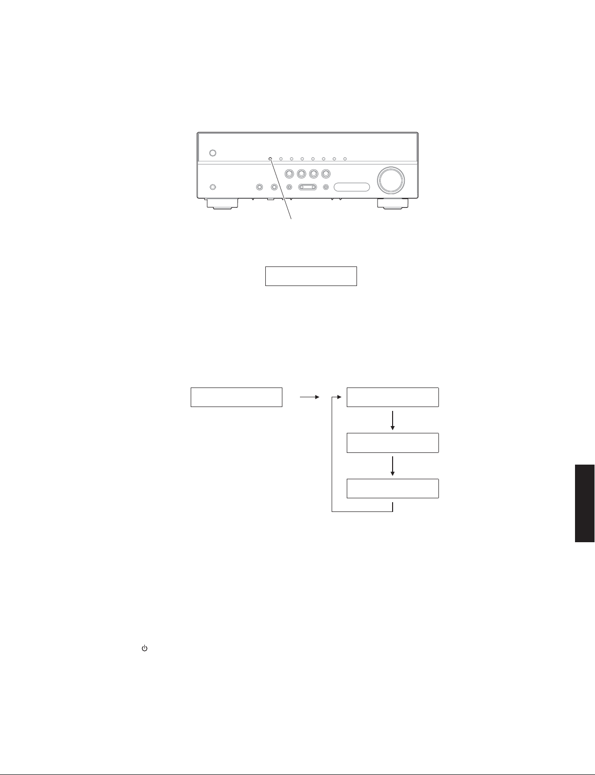
● Display provided when Self-Diagnostic Function started
The display is as described below depending on the situation when the power to this unit is turned off.
1. When the power is turned off by usual operation:
“NO PROTECT” is displayed. Then “1. ANALOG BYPAS” is displayed in a few seconds.
Main menu displayOpening message
After a few seconds
NOPROTECT 1.ANALOGBYPAS
2. When the protection function worked to turn off the power:
The information of protection function which worked at that time is displayed. Then “1.ANALOG BYPAS” is displayed in a
few seconds.
Note: At that time if you restart the self-diagnostic function after turning off the power once, “NO PROTECT” will be
displayed. That is because that situation is equal to “1. When the power is turned off by usual operation:”.
However history of the protection function is stored in a back-up IC. For details, refer to “21. PROTECTION
HISTORY” menu.
2-1. When the protection function worked due to excess current.
PSPRT:xxxL
AD value when the protection function is working
Cause: An excessive current flowed through the power amplifier.
Supplementary information: As current of the power amplifier is detected, the abnormal channel can be identified by
checking the current detect transistor.
Turning on the power without correcting the abnormality will cause the protection function to work immediately and the
power supply will instantly be shut off.
Notes:
• Applying the power to this unit without correcting the abnormality can be dangerous and cause additional
circuit damage. To avoid this, if “PS” and “DC” protection function works 3 times consecutively, the power will
not turn on even when the “
In order to turn on the power again, disconnect the power cable from the AC outlet once and then reconnect it
again.
• The output transistors in each amplifier channel should be checked for damage before applying power to this unit.
• Amplifier current should be monitored by measuring DC voltage across the emitter resistors for each channel.
” (Power) key is pressed.
NS-C20/NS-SWP20
HTR-2064/NS-B20/
27

HTR-2064/NS-B20/NS-C20/NS-SWP20
2-2. When the protection function worked due to a short between speaker terminals.
IPROTECT
Cause: The line between speaker terminals is shorted.
Supplementary information: As the excess current is detected after operation of the speaker relay, the shorted speaker
terminal and the connected speaker can be identified.
Turning on the power without correcting the abnormality will cause the protection function to work immediately and the
power supply will instantly be shut off.
2-3. When the protection function worked due to abnormal DC output.
DCPRT:xxxH
AD value when the protection function is working
Cause: DC output of the power amplifier is abnormal.
Supplementary information: The protection function worked due to a DC voltage appearing at the speaker terminal. A
cause could be a defect in the amplifier.
Turning on the power without correcting the abnormality will cause the protection function to work in 3 seconds and the
power supply will be shut off.
2-4. When the protection function worked due to abnormal voltage in the power supply section.
Cause: The voltage in the power supply section is abnormal.
Supplementary information: The protection function worked due to a defect or overload in the power supply.
Turning on the power without correcting the abnormality will cause the protection function to work in 1 seconds and the
power supply will be shut off.
2-5. When the protection function worked due to excessive heatsink temperature.
HTR-2064/NS-B20/
NS-C20/NS-SWP20
Cause: The temperature of the heatsink is excessive.
Supplementary information: The protection function worked due to the temperature limit being exceeded.
Causes could be poor ventilation or a defect related to the thermal sensor.
Turning on the power without correcting the abnormality will cause the protection function to work in 1 seconds and the
power supply will be shut off.
PSPRT:xxxL
AD value when the protection function is working
TMPPRT:xxxL
AD value when the protection function is working
* For detection of each protection function, refer to main menu described later.
● History of protection function
When the protection function has worked, its history is stored in memory as backup data.
Even if no abnormality is noted while servicing this unit, an abnormality which has occurred previously can be defined
as long as the backup data has been stored.
The history of the protection function will be initialized when self-diagnostic function is cancelled with “24-2. PRESET
RESERVED” (Memory initialized) menu selected.
28

HTR-2064/NS-B20/NS-C20/NS-SWP20
● Operation procedure of Main menu and Sub-menu
There are 26 main menu items, each of which has sub-menu items.
Main menu selection
Select the main menu using “SCENE TV” (forward) and “SCENE BD/DVD” (reverse) keys.
Sub-menu selection
Select the sub-menu using “SCENE RADIO” (forward) and “SCENE CD” (reverse) keys.
Keys of this unit
Main menu selection
Reverse
Forward Reverse Forward
Sub-menu selection
● Functions in Self-Diagnostic Function mode
In addition to the self-diagnostic function menu items, functions listed below are available.
• Power ON/OFF
• Master volume
• Muting
• Input selection
* Functions related to the tuner and the set menu are not available.
NS-C20/NS-SWP20
HTR-2064/NS-B20/
● Initial settings when Self-Diagnostic Function started
The following initial settings are used when self-diagnostic function is started.
When self-diagnostic function is canceled, these settings are restored to those before starting self-diagnostic function.
• Master volume: -20 dB
• Input: AUDIO5
• Main menu: 1. ANALOG BYPASS
• Speaker setting: LARGE, Bass out to SWFR (All channels)
29
Loading...