

Page 1
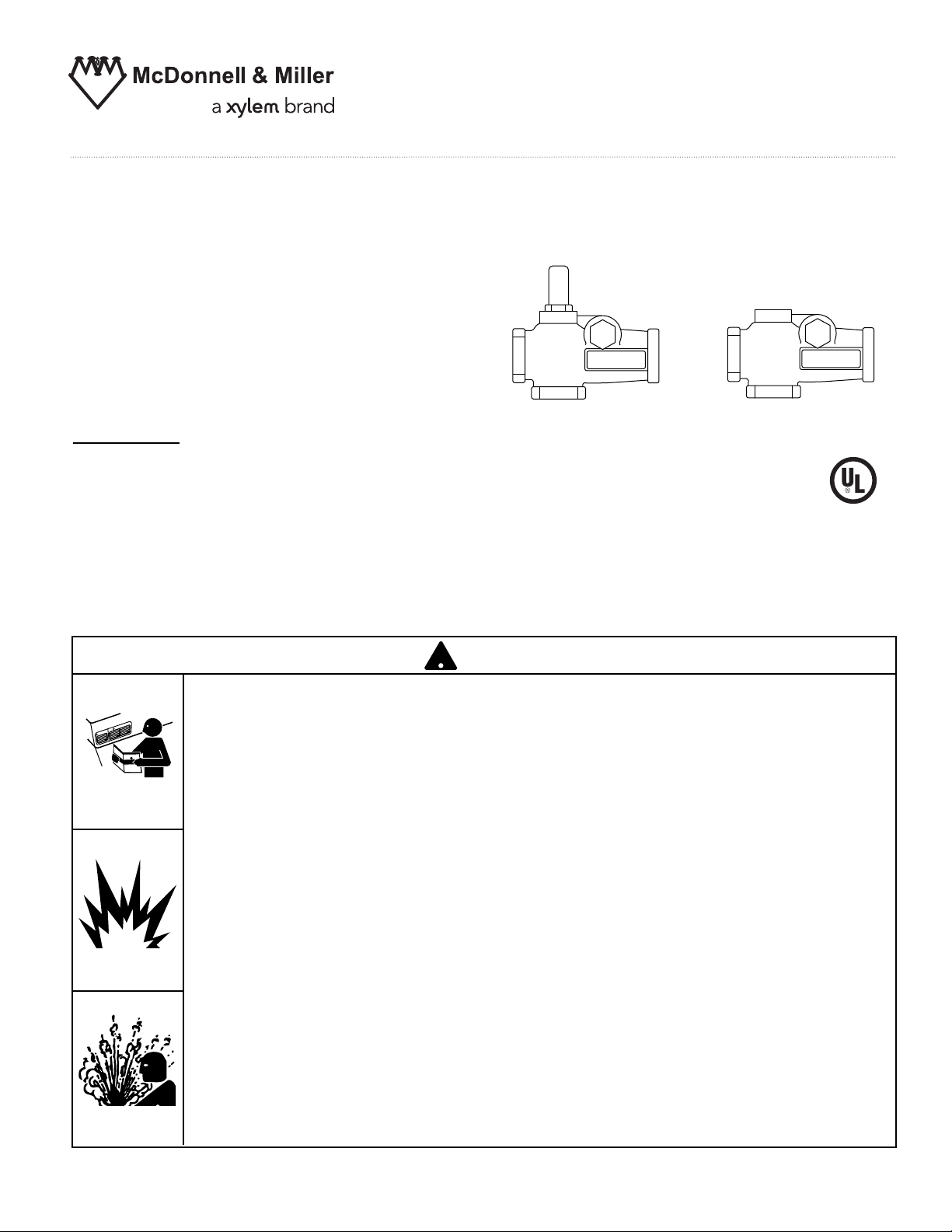
Model TC-4
Test-N-Check®Valves
For Hot Water Boilers
Does in minutes what used to
take hours.
INSTRUCTION MANUAL
MM-802F
Applications:
For isolation of equalizing lines during low
water cut-off testing.
OPERATION
Maximum Operating Pressure: 160 psi (11 kg/cm2)
Maximum Operating Temperature: 250˚F (121˚C)
!
N
UTIO
A
C
G
NIN
R
A
W
• Before using this product read and understand instructions.
• Save these instructions for future reference.
• All work must be performed by qualified personnel trained in the proper application, installation, and maintenance of plumbing, steam, and electrical equipment and/or systems in
accordance with all applicable codes and ordinances.
• To prevent serious burns, the boiler must be cooled to 80˚F (27˚C) and the pressure must be
0 psi (0 bar) before servicing.
TC-U Upper Valve TC-L Lower Valve
WARNING
• To prevent serious personal injury from steam blow-down, connect a drain pipe to the control
opening to avoid exposure to steam discharge.
California Proposition 65 warning! This product contains chemicals known to the
•
state of California to cause cancer and birth defects or other reproductive harm.
Previous controls should never be installed on a new system. Always install new
•
controls on a new boiler or system.
Failure to follow this warning could cause property damage, personal inj ury or death.
CAUTION:
•
A more frequent replacement interval may be necessary based on the condition of
the unit at time of inspection. McDonnell Miller s warranty is one (1) year from date
of installation or two (2) years from the date of manufacture.
!
&
'
Page 2
2
Simplify Testing of Low Water Cut-offs on Hot Water Boilers
TEST-N-CHECK®VALVES
IMPORTANT:
• When using tape sealant or thread joint compound on pipe or fittings with external threads follow
manufacturer’s instructions. Do not use tape sealant or thread joint compound on first thread.
To prevent serious personal injury from steam pipe blow down, connect a
drain pipe to the control opening to avoid exposure to steam discharge.
If vacuum breaker stem is accidentally depressed, hot water could be discharged causing burns.
Failure to follow this caution could cause personal injury.
!
CAUTION
TEST-N-CHECK VALVES
SIMPLIFY TESTING OF LOW WATER CUT-OFFS
ON HOT WATER BOILERS
Good operating practice requires installation of a low
water cut-off on a hot water boiler and that it be
checked regularly to make certain the control will
function properly in the event of a low water condition.
Boiler owners and installers need a quick and efficient
way to test a low water cut-off on a hot water boiler.
Simply opening a blow-off valve below the float
chamber may not serve as a valid test and is excessively
wasteful of boiler water and fuel. The water
level in the float chamber, and the float, must drop far
enough to start the control through its cycle of operation.
However, water flowing in through the equalizing
piping may replenish the level in the float chamber fast
enough to delay the necessary float drop, or prevent it
altogether.
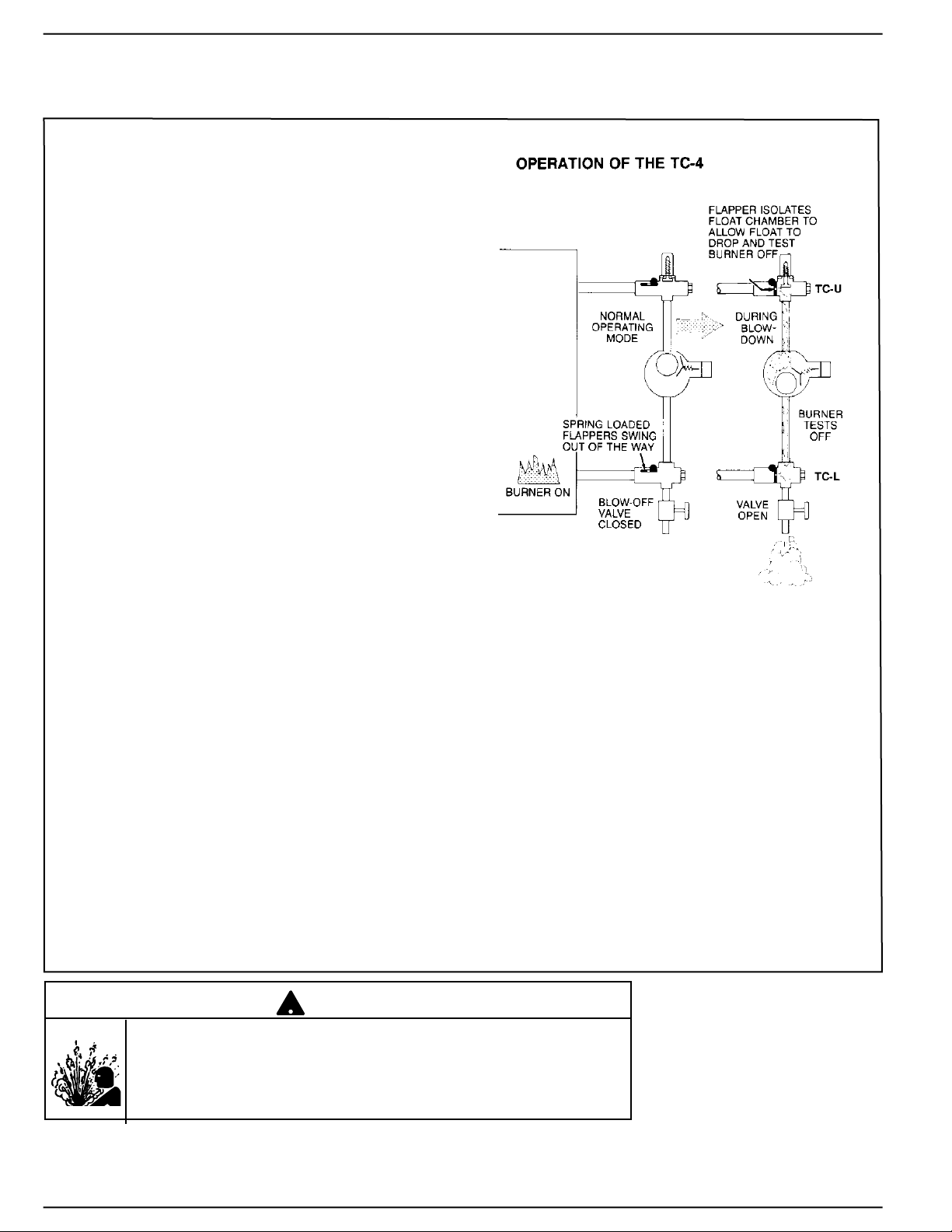
McDONNELL & MILLER Test-N-Check Valves have
been specially designed for such installations. In normal
operation, they allow free circulation of water through
the equalizing piping and float chamber. But any sudden
onrush of water, such as caused by opening the blowoff,
snaps shut a damper in each valve to restrict flow
to the float chamber. Water level in the float chamber
falls quickly to start the control through its operating
cycle, with a minimum loss of boiler water. When
blow-off is closed, dampers return to normally open
position.
McDONNELL & MILLER Test-N-Check Valves simply
replace the crosses above and below the control in the
equalizing lines. Valves have the same dimensions as
standard crosses and nipple in the horizontal leg, and
allow normal rod clean-out of pipe in both directions.
Connections are 1" NPT female tappings.
Upper and lower valves are identical, except that the
upper valve has vacuum breaker built in to allow for
rapid evacuation of the float chamber. They are furnished
in sets-one upper and one lower valve, to
equip one equalizing line. They can be used with all
McDONNELL & MILLER Low Water Cut-Offs for hot
water boilers.
®
LWCO
®
®
Page 3

1. Remove the existing low water cut-off by dis-
connecting the unions in the equalizing lines.
2. Remove the crosses from the upper and lower
equalizing lines.
3. Assemble the TC-U (the upper Test-N-Check
valve, with the vacuum breaker) into the upper
equalizing line replacing the cross. NOTE: The
vacuum breaker must be on the top and the
long leg must face the boiler.
4. Assemble the TC-L (the lower Test-N-Check
valve, without the vacuum breaker) into the
lower equalizing line replacing the cross.
NOTE: The brass cap must be located above
the center of the lower equalizing line, and the
long leg must face the boiler.
5. Assemble the blow-down valve into the bottom
port of the TC-L.
6. Assemble 1” NPT pipe plugs into the remaining
open port in both the TC-U and TC-L.
NOTE: The addition of the Test-N-Check valves
in place of standard crosses will extend the low
water cut-off approximately 2” farther from the
boiler.
7. Reassemble the low water cut-off and vertical
equalizing pipe to the upper and lower Test-NCheck valves.
8. After all piping assembly has been completed,
refill the system with water, turn on all electrical
supply and bring system to operating conditions. After system reaches operating pressure,
inspect to make sure no leaks exist at the
threaded connections. Test valves by opening
blow-down valve while burner is on to make
sure valves operate correctly and low water cutoff shuts burner off.
Installation of the TC-4 Test-N-Check Valve with an Existing Low Water Cut-off
IMPORTANT:
• When using tape sealant or thread joint compound on pipe or fittings with external threads follow
manufacturer’s instructions. Do not use tape sealant or thread joint compound on first thread.
To prevent serious personal injury from steam pipe blow down, connect a
drain pipe to the control opening to avoid exposure to steam discharge.
If vacuum breaker stem is accidentally depressed, hot water could be discharged causing burns.
Failure to follow this caution could cause personal injury.
!
CAUTION
®
®
®
LWCO
®
REMOVE CROSS
®
TC-U in Place
TC-L
in Place
LWCO
Brass
Cap
Blow-down Valve
Page 4

3
1. Assemble the TC-U (the upper Test-N-Check
valve, with the vacuum breaker) into the upper
equalizing line in place of the cross described
in the low water cut-off installation instructions.
NOTE: The vacuum breaker must be on the top
and the long leg must face the boiler. NOTE:
Make sure low water cut-off position is located
in accordance with the boiler manufacturer’s
recommended cut-off level.
2. Assemble the TC-L (the lower Test-N-Check
valve, without the vacuum breaker) into the
lower equalizing line in place of the cross
described in the low water cut-off installation
instructions. NOTE: The brass cap must be
located above the center of the lower equalizing
line, and the long leg must face the boiler.
3. Assemble the blow-down valve into the bottom
port of the TC-L.
4. Assemble 1” NPT pipe plugs into the remaining
open port in both the TC-U and TC-L.
5. Complete the installation as described in the
low water cut-off installation instructions.
6. After all piping assembly has been completed,
refill the system with water, turn on all electrical
supply and bring system to operating conditions. After system reaches operating pressure,
inspect to make sure no leaks exist at the
threaded connections. Test valves by opening
blow-down valve while burner is on, to make
sure valves operate correctly and low water cutoff shuts burner off.
Simplify Testing of Low Water Cut-offs on Hot Water Boilers
TEST-N-CHECK®VALVES
Installation of the TC-4 Test-N-Check Valves with a New Low Water Cut-off
To prevent serious personal injury from steam pipe blow down, connect a
drain pipe to the control opening to avoid exposure to steam discharge.
If vacuum breaker stem is accidentally depressed, hot water could be discharged causing burns.
Failure to follow this caution could cause personal injury.
!
CAUTION
IMPORTANT:
• When using tape sealant or thread joint compound on pipe or fittings with external threads follow
manufacturer’s instructions. Do not use tape sealant or thread joint compound on first thread.
®
®
TC-U in Place
®
LWCO
TC-L
in Place
Brass
Cap
Blow-down Valve
Page 5

Xylem
1) The tissue in plants that brings water upward from the roots;
2) a leading global water technology company.
We’re 12,500 people unified in a common purpose: creating innovative solutions
to meet our world’s water needs. Developing new technologies that will improve
the way water is used, conserved, and re-used in the future is central to our work.
We move, treat, analyze, and return water to the environment, and we help people
use water efficiently, in their homes, buildings, factories and farms. In more than
150 countries, we have strong, long-standing relationships with customers who
know us for our powerful combination of leading product brands and applications
expertise, backed by a legacy of innovation.
For more information on how Xylem can help you, go to www.xyleminc.com
Xylem Inc.
8200 N. Austin Avenue
Morton Grove, Illinois 60053
Phone: (847) 966-3700
Fax: (847) 965-8379
www.xyleminc.com/brands/mcdonnellmiller
McDonnell & Miller is a trademark of Xylem Inc. or one of its subsidiaries.
© 2013 Xylem Inc. MM-802F July 2013 Part No. 210088
 Loading...