


Global Water
800-876-1172 • globalw.com
Global Water
Instrumentation, Inc.
151 Graham Road
P.O. Box 9010
College Station, TX 77842-9010
T: 800-876-1172
Int’l: (979) 690-5560, Fax: (979) 690-0440
E-mail : globalw@globalw.com
PC320 Process Controller
02-107
Publication Number 39370712
- 1 -

Global Water
800-876-1172 • globalw.com
Congratulations on your purchase of the Global Water PC320 Process
Controller. This instrument has been quality tested and approved for
providing accurate and reliable measurements. We are confident that you
will find the monitor to be a valuable asset for your application. Should you
require assistance, our technical staff will be happy to help.
Table of Contents
I. PC320 Process Controller Description • • Page 3
II. PC320 Specifications • • • • 5
III. Display Modes • • • • • 6
IV. Switch Settings • • • • • 7
V. Sensor Input • • • • • 8
VI. 4-20mA Output • • • • • 8
VII. Relay Operation • • • • • 8
VIII. Power Saving Mode • • • • • 11
IX. Scientific Notation • • • • • 11
X. Programming Setup Parameters • • • 11
XI. Data Logger Option • • • • • 17
XII. Technical Support • • • • • 17
XIII. Appendix A: Terminal Strip Diagram • • • 19
* Copyright Global Water Instrumentatio n, Inc. 2012
- 2 -

Global Water
800-876-1172 • globalw.com
I. PC320 Process Controller Description
The PC320 Process Controller is reliab le, accurate and suitable for measuring
any type of 2 and 3 wire sensors with 4-20 mA, 0-1 volt and 0-5 vo lt o ut put s.
The controller comes pre-programmed for use with 12 different common
sensor types and appropriate selectable engineering units. In addition, the
PC320 can be programmed by the user to monitor any type of custom sensor
in any user defi ne d u ni ts. Custom user defined engineering units are also
programmable for all standa rd sensor types. Both 2-poi nt and 3-point
calibration methods are supported and an additional 3
equation can be applied t o the sensor data to correct for non-linearities in
sensor output. The polynomial mode is useful for calculating other
parameters ba se d on a sensor reading such as calculating water flow rate
from water level.
The PC320 controller is enclosed in a NEMA 4 enclos ure and is easily
programmed and calibrated in the field using the water resistant 8 button
keypad and 2-line LCD display, by going through a series of simple menu
options.
The LCD display shows what type of sensor is being monit ored, the data
reading aver aged over a user programmable time period, and the engineering
units selected. The display also shows the current On or Off state for each of
the 4 relays. Two other display modes are available. One shows the
maximum and minimum se nsor readings since last rese t. Another m ode
displays the current sta te of any of the 4 relays in real time, the s ensor
reading tha t caused the last triggerin g event, and the On or Off time
remaining in the control cycle. The LCD display can be backlit for easy
viewing at all times and offers a power saving m ode for limiting curre nt
drain in battery powered applica ti ons.
Four relays are pr ovided for controlling external devices including samplers,
alarms, mixers, pumps, control valves, floodgates and telemetry systems.
Each relay is independe ntly program mable to trig ger on maximum and/or
minimum threshold le ve ls in one of five different control modes.
Relay opera tion is defined by setting upper and low e r sens or thr e sh old levels
and turning relays on when sensor readings exceed a normally defined range.
rd
order polynomial
- 3 -

Global Water
800-876-1172 • globalw.com
Both normally open and normally closed relay contacts are provided. Relay
modes include a One Time tr igger that will engage a relay one time only for
a programmed on time period when a sensor reading falls outside of a
defined normal range. The Steady state mode will turn on a rela y as long as
the sensor readin g is ou t of the normal ran ge. The Cyclic mode will
continually turn a relay on and off for user definable on and off times while
the sensor readin g is outside of normal range. Additionally, High Control
and Low Control Modes are provided. These modes are used for maintaining
a sensor rea ding within a specific range; for example keeping the water level
in a tank between tw o predefined levels. A sixth mode allows a relay to be
deactivated regardles s of sett in g s. There are also programmable Delay
Times and Hysteresis. Setting a Delay Time will delay a relay from turning
on for that amount of tim e when a sensor reading falls outside of normal
range. This is used to limit the effect of rapidly changing sensor reading s
and keeping the relays from reacting q uickly to very small changes near a
threshold setting. The Hysteresis function allows the relay to r emain on until
the sensor readin g fa l ls int o the normal range again, plus a defined hy ste re si s
percentage . This also prevents the relays from overreacting to rapidly
changing events near a threshold level. A test mode is provided for manually
testing rela y operation.
A fully scala ble 4-20mA output i s available for recording sensor data
readings by devices like data loggers, PLC’s, telemetry systems and chart
recorders. There is a factory installed USB data logger option available that
can record these data readings to memory at regular intervals, as well as the
exact times of all changes in relay states and the current sensor reading at t hat
time. Contact a Sales or Technical Support representative for m ore
informatio n. To easily interpret this sensor and relay data, a free sof tw ar e
package is available. A separate manual titled “ FC220-PC320 Data Logger
Option” describes this i n more detail and is available for free download at
globalw.com/support.
- 4 -

Global Water
800-876-1172 • globalw.com
II. PC320 Specifications:
Power Requirements: 12VDC or 18-24VDC Input, +/-10%
Supply Curr ent: 13mA + Sensor Current + B acklight + 4-2 0mA Output
150mA M aximum Total Cur rent
Backlight C urrent: 23mA when on
Internal Fuse: 315mA
Power Adap tor: 18VDC Universal Power Supply, 90-220VAC Input
AC Version only
Sensor Types/Units: Level (Feet, Inches, Meters, Centimeters, C ustom)
Temperature (ºF, ºC, Custom)
pH (ph, Custom)
Conducti vity (uS, mS, C ustom)
Dissolved Oxygen (%, mbar, ppm, mg/L, Custom)
ORP (mV, Custom)
Turbidity (NTU, Custom)
Wind Speed (MPH, KPH, Ft/Sec, M/Sec, Custom)
Wind Direction (º, Cus tom)
Humidity (%, Custom )
Solar Radiation (W/M², Custom)
Pressure ( mbar, hPa, inHg, PSI, Pa, Custom)
Custom (Custom)
Output Relays: 4 Independent S PDT Relays
Contact Rating: 8A @ 250VAC, 5A @ 30VDC Resistive
Level Sensor Input: 2-Wire or 3-wire, 4-20mA, 0-5VDC, 0-1VDC
Output: 4-20mA Scalable
Display/Keypad: 16 Character x 2 Line Backlit LCD, 8-Button Tactile Keypad
Sensor Resolution: 7 Digit Maximum, Auto-Floating point
Accuracy: Sensor Accuracy + 0.1% + 1 Digit
Dimensions: 7.1”W x 5.1”H x 1.4D (180mm x 130mm x 35mm)
Weight: 1 lb
- 5 -
Global Water
800-876-1172 • globalw.com
III. Display Modes
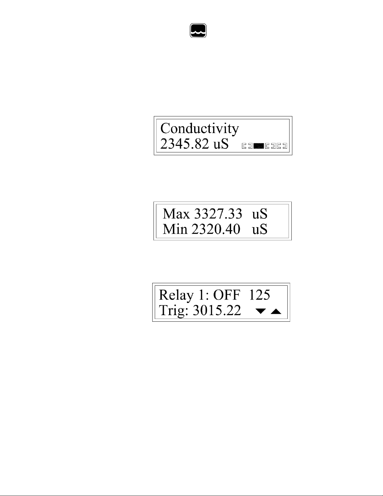
The PC320 has three display mode s, pressing the DISPLAY button on the fron t pane l
cycles through them: Sensor Reading > Max/Min > Relay Status > Sensor Reading ...
Sensor Reading
The top line shows the sensor type. The second line shows the current sensor reading
and units updated once eac h second. The brackets to the right of the sensor read ing
indicate the current on or off status of each of the 4 relays, relay 1 to the left and relay
4 to the right. When the brackets are fil led the relay is on. In the above example, relay
2 is on and the others are off.
Max/Min
This display mode shows t he minimum and maximum re adings since la st reset. To
reset the display, press SAVE for 2 sec onds. Pressing SAVE also turns off all 4 relays.
Once reset, the relays will not trigger again for 15 seconds.
Relay Status
This display mode shows t he current status for each of the relays. Use the UP and
DOWN arrow buttons to scroll through relays 1-4. The top line shows the relay
number, whether it is currently on or off, and how many seconds remain in the on or
off cycle, if applicable . Depending on the relay mode selected, the on and off times
may not apply and would not be displaye d. The bottom line shows if that relay has
been trigge red since last reset. If the relay has been triggered, the sensor reading at the
time of triggering is shown. If the relay has not been triggered, “None” will be
displayed. The relays are turned off and the status reset when the SAVE button is
pressed for 2 seconds. Once reset, the relays will not trigger for 15 seconds. In the
above example, relay 1 is currently off with 125 seconds remaining before it is turned
on again. The relay was last triggered by a sensor reading of 3015.22 uS.
- 6 -

Global Water
800-876-1172 • globalw.com
IV. Switch Settings
Inside the PC320 is a bank of 8 swi tches which are used to select the sensor type and
power input. Select the switches as follows:
Select only one of SW1 and SW2, leave the other switch off
SW1: ON, Sensor power is 12 vol ts
SW2: ON, Sensor power is 18-24 volts depending on the voltage input to the
Note this feature is not available when running from a 12 volt battery
SW3: ON, Sensor power is continuous
SW3: OFF, S ensor power is switched on and off by the microprocess or in power
saving mode. If not using power saving mode, set SW3 to ON.
SW4: ON, Sensor type is 4-20mA
SW4: OFF, S ensor type is 0-5 VDC or 0-1 VDC
SW5: ON, Sensor type is 4-20mA or 0-5 VDC
SW5: OFF, S ensor type is 0-1 VDC
SW6: This switch is unused
Select only one of SW7 and SW8, leave the other switch off
SW7: ON, Power input to the PC320 is 18-24 VDC
SW8: ON, Power input to the PC320 is 12 VDC
- 7 -

Global Water
800-876-1172 • globalw.com
V. Sensor Input
The PC320 accepts any analog sensor with a 4-20mA, 0-5VDC or 0-1VDC output.
Available power for the sensor depends on the power input to the PC320. When
powering the PC320 from 12 volts, the sensor pow er is also 12 volts. If you are
running from a power supply of 18-24 volts, the sensor power can be se lected from
either a regulat ed 12 vo lt s upply, or directly from the 18-24 volt input. The power can
also be conne cted continuously or it can be set to be tur ned on and off by the PC320
when using a powe r saving mode . In this mode the sensor is t urned on at user defined
intervals f or a programmable warm-up time, then turned off again to conserve powe r.
VI. 4-20mA Output
A 4-20mA output is prov ide d tha t is pro p ort i ona l to any defined sensor range. This
allows the data history to be re corded by an external data logger or PLC, or by the
internal da ta logger option, or both. The output is fully scalable and allows the user to
select the sensor ranges that are proportional to the 4mA and 20mA output currents.
VII. Relay Operation
Several settings independently control the operat ion of the 4 relays. These settings are
Upper Threshold, Lower Threshold, Hysteresis, Delay Time, Relay Mode, On Time
and Off Time. Not all of these settings m ay apply depending on which relay mode is
selected.
The Upper and Lower Threshold settings establish a normal band whic h the sensor
reading should remain in. If a sensor reading rises above the Upper Threshold, the
relay will trigger. Likewise; if the sensor reading f alls below the Lower Threshold, the
relay will a lso trigger. If either the U pper or Lower Thresholds are not needed, they
should be set to a value outside of the sensor output.
Example: A water level sensor has a range of zero to 15 feet and is install ed in a wat er
tank to control a pump. Relay 1 has an Upper Thre shold of 10 f eet and a Lower
Threshold of 5 feet. The relay may trigger (depending on mode) when the water leve l
rises above 10 feet or falls below 5 feet. I f it is desired for the relay to turn on only
when the level is above 10 fe et, but not below 5 feet; change the Low er Threshold t o a
value outside of the normal range of the sensor, li ke a negative number (-10 feet).
- 8 -

Global Water
800-876-1172 • globalw.com
Since in norm al use the water level will never fall below zero, the Lowe r Threshold
will have no effec t an d not tr ig ger th e rel ay .
Hysteresis is a percentage change of the full span of the sensor required to turn a relay
off again once it has been triggered. This is used to keep the relays from turning on
and off too often whe n a se nsor reading is very near a t hreshold level. Note that the
percentage is of the span the sensor is ca librated for, not necessarily the full range of
the sensor. If there is a pH sensor capa ble of measuring from 0-14, but is calibrated at
a pH of 4 and 10, the span is considered 10-4 or 6 pH units. If the Hysteresis is set to
10%, that is equivalent to 10% of 6 or 0.6 pH units. The maximum hysteresis is 25%.
Example: A water level sensor monitors the level in a tank and the PC320 is
connected to a pump; which will pump water out of the tank. The Upper Threshold is
set to 10 feet and the Hyste resis is set to z ero. When the level rises a bove 10 feet, the
pump will turn on. When the level falls t o 9.999 feet, the pump will turn off. Thus;
the pump will turn on and off re peatedly trying to maintain the level at exactly 10 feet.
The level se nsor has a total calibrated span of 15 feet and 10% of that is 1.5 feet. If the
Hysteresis is set to 10%; the relay will trigger when the level rises to 10 feet, pumping
water from the tank. The pump will not t urn off again until the leve l falls to 10 feet
minus 10% or 8.5 feet. The level in the tank will be m aintained between 8.5 and 10
feet, saving the pump fr om turning on and off so often and wearing it out.
Example: A te mperature sensor has a span of -50ºC to +50ºC, or 100 degrees
centigrade. The controlle r is set to turn on a heater when the temperature falls below
25ºC (Lower Threshold). The Hysteresis is set to 5% or 5ºC (5% of 100º span). The
heater will turn on just below 25ºC but not turn off until the temperature rises to 25C +
5% or 30C. The normal tempera ture range in the tank will be 25ºC to 30ºC.
The Delay Time is the amount of time require d for a sensor reading to be above or
below a threshold level before a rel ay is turned on. This can be used to prevent a relay
from triggering when a sensor reading briefly falls outside of a nor mal range.
Maximum delay time is 99 seconds.
- 9 -

Global Water
800-876-1172 • globalw.com
Relay Modes:
Off: In Off mode, relays will not turn on regardless of settings
One Time: In One Time mode, a relay will turn on one time only when a sensor
reading is a bove or below a threshold level. The relay will turn on for the programmed
On Time, then turn off regardless of sensor reading. If during the On Time the sensor
reading returns to a normal range, the relay will turn off even if the On Time has not
elapsed. Once the On Time has elapsed, t he relay will remain off un til the sensor
reading returns to a normal level (between thresholds), and then crosses past a
threshold level again. The Off Time does not apply in this mode an d has no effect on
relay opera tion, the Delay Time and Hysteresis set tings do apply.
Steady: In Steady (Steady State) mode the relay will turn on when a sensor reading is
outside of the normal range, and stay on. The relay will remain on as long until the
sensor reading is outside of the th re sh ol d poi nts. The Delay Time and Hysteresis
settings are used in this mode. Programmed ON and Off times do not apply.
Cyclic: In cyclic mode the relay will trigger when a sensor reading falls outside of the
threshold settings. The relay will tur n on for the On Time, then off for the Off Time.
The cycle of on and off wil l continue until the sensor reading falls w ithin a normal
range again. The De lay Time and Hysteresis set ting apply in this mode.
High Control: In High Control mode, the relay will turn on when the sensor reading
rises above the Upper Threshold. The relay will remain on until the sensor reading
falls below the Lower Threshold. This mode could be used to turn on a pump when a
water level rises above 10 feet and continue to pum p until the level falls below 5 feet.
Delay Time does apply. On Time, Off Time and Hysteresis do not apply and have no
effect on relay operation.
Low Control: This mode is the opposite of High Control mode. The relay will turn
on when a sensor reading falls below the Lower Threshold and remain on until the
sensor reading rises abo ve the Upper Threshold. This might be used to pump water
into a tank when the level falls below 5 feet and continue t o pump until the level rise s
above 10 feet. Delay Time does apply. On Time, Off Time and Hysteresis do not
apply and have no effect on relay operation.
- 10 -

Global Water
800-876-1172 • globalw.com
VIII. Power Saving Mode
A power saving mode is provided that allows the operating current to be reduce d in
remote monitoring applications. One w ay this is acc omplished is to turn off the L CD
display backlight, this saves about 20mA of current. Three modes allow the user to
turn the backli ght on a ll the time, off all the time, or turn it on for one minute only. In
this last mode, the backl ight will come on for one minute when any of the buttons on
the keypad are pressed, then turn off again after one minute of in ac tiv ity . The sensor
can also be t urned on and off periodically to reduce power consumption. The user can
program a sample rate of 0-60 minutes, an d can set the sensor warm-up time of 0-60
seconds. Example: The sample rate is 3 0 minutes and the warm-up time is 3 seconds.
The sensor will be turned on for 3 secon ds every 30 m inutes then shut off again.
During the time the sensor is off the LCD display and 4-20mA output will indicate the
last sensor reading. The relays will continue to oper ate, based on that last reading.
After 30 m inutes more, a new reading will be taken and the display and 4-20mA
output updated again. Note that usin g the 4-20mA output will incr ease the current
draw by an am ount e qu al to the out p ut cur r en t. It is also possible to fail to react to
rapidly changing events.
IX. Scientific Notation
Scientific no tat i on is used in the PC320 for enterin g parameters for the Polynomial
mode and is generally used for di splaying very large or very small numbers. It
represents a number as being multiplied by 10 raised to a power, such as 5.67*10^2
being equal to 567 since 10^2 equals 100 (10^2 = 10²). The n otation E2 is a lso
equivalent to “shift the decimal point to the right two times”. This makes the di splay
of large and small num bers easi er to rea d; 5.6 7E 3 is 5.6 7 th ousand or 5670, 5.67E6 is
5.67 million, etc. In the s ame way, small numbers less that one can be shown as 10
raised to a negative power, or “shift the decimal point that m any times to the left”;
such as 5.67E-3 = 0.00567 or 5.67 thousandths, 5.67E-6 = .00000567 or 5.67
millionths.
X. Programming Setup Parameters
Press the MENU button for 2 seconds to enter the setup menu. Pressing the MENU
button again cycles through the differ ent setup options. Pressi ng the BACK button
moves backw ard to the previous display. Pressing the DISPLAY button from any
menu exits se tu p and r et urn s to t he normal display mode. Press the RIGHT arrow
- 11 -

Global Water
800-876-1172 • globalw.com
button to enter any of the setup sub-menus. These sub-menus are Set Sensor Type,
Calibrate Sensor, Polynomial Mode, 4-20mA Output Calibration, Decimal Places,
Averaging Time, Power Saving, Relay Settings, and Relay Test Mode. Note that while
in the setup menus, all normal operations will stop. After one minut e of in act i vit y,
the PC320 will automat ically return t o the main disp lay and operat ion mode.
Set Sensor Type:
Press the RIGHT arrow button to enter this or any other su b-menu. To change the
sensor type, use the UP and DOWN arrow buttons to scr oll through the different preprogrammed sensor types, or to select the “Custom” sensor option. Select the sen sor
type and press SAVE. Pre ss MENU to m ove forward to the units menu. Each sensor
type has pre-defined engineering units to c hoose from, a s well as a “Custom” setting
that allows the units to be set to any 4 character symbol. Select the desired units and
press SAVE. For the case of custom sensor or custom units, press the LEFT and
RIGHT arrows to select a character to change, then use the UP and DOWN arrow
buttons to scro ll thr oug h up per an d lowe r ca se let te r s, numbers, and a list of spec ia l
characters. When all characters in the custom senso r name or units menus have be en
changed, pre ss SAV E to stor e them to memory. A list of standard sensors and units is
shown in the Specifications Section of this manual. Custom Sensor names are limited
to 16 characters an d Cus t om Units are limited to 4.
Calibrate Sensor:
To change or check the sensor calibra tion press the RIGHT arrow button. To skip the
calibration option press the MENU ke y to move to the next programming option.
- 12 -

Global Water
800-876-1172 • globalw.com
First select whether the sensor will be calibrated using a 2 or 3 po int method.
Generally ; sensors are calibrated at 2 points as close to the ends of the sensor’s
measurement range as possible. For example: A 15 foot water level sensor wou ld be
calibrated us in g a 2-point method and be set at zero feet and as close to 15 fee t as
practically possible. However; a pH sensor with a range of 0-14 m ay be typically
calibrated at a pH of 4 and 10 due to the hazards of using very strong acids and bases.
Calibrating a sensor at points other than the full range of the sensor wi ll no t st op the
PC320 from measuring the full sensor range, but may slightly decrease the overall
accuracy . A ph sensor migh t also be calib rated using a 3-point method at pH values of
4, 7 and 10. U sing a 3-point calibration will increase the accuracy of sensors that have
small amounts of nonlinea rity.
After selecting the number of calibration points, press SAVE and MENU. Using the
arrow buttons, set the High Value to the upper calibration point, first setting the +/sign, then separately each digit. If you are calibrating a 15 foot water level sensor but
only have an 8.5 foot column of water, set the High Value to +8.500 00. If you are
using a pH 10 buffer solut ion to calibrate a 0-14 pH sensor, set it to +10.0000. Use the
UP and Down b uttons to cha nge the sign t o + or -. Use LEFT and RIGHT to select
each digit, then UP and Down to change it in the range of 0-9 or decimal point. Press
SAVE when d one and then MENU to move forward. Next place the sensor in a
condition that corresponds to the Hi gh Value previously set, or use a loop or process
calibrator. Press SAVE to store the High Raw data number, then MENU. For 3-point
calibration, the next menu will allow you to set the middle calibr ation point; then the
Low point. A 2-point calibration will skip the middle point and jump to the L ow point.
Set each of these Middle and Low calibration points in the same wa y as the High.
Polynomial Mode:
The calibration process previously discussed can be further modified. This is best
described w ith an example that will use a water level sensor and from this level da ta,
calculate the water flow rate in a flume.
Calibrate a w ater level sensor as previously described. When selecting the sensor type,
you can use the Custom Se nsor and Units selection; the sensor name and units
displayed don’t actually have anything to do with calculations, they are just used as
- 13 -

Global Water
800-876-1172 • globalw.com
identifier s for the user on the LCD displa y. Calibrate the sensor nor mally. You can
set the sensor ty pe to Water Flow and the units to CFS (Cubic Feet per Second) .
A flume or w eir equation u sually has the form of Q = A * B ^ C; where Q is flow in
CFS, A is a multiplier, B is water level in feet and C is an exponent applied to B.
However; in many cases a 3
rd
order polynomial can give a close appr oximation of
flow. Example: The flow equation for a 3” Parshall Flume is:
Water Flow (C FS) = 0.994 * [(Water Level in Feet) ^ 1.55]
rd
A 3
order polynomial can approximate this with:
CFS = -1.499E-2 + [3.746E-1 * Level] + [7.164E-1 * Level^ 2] – [8.771E-2 * Level^3]
The accuracy of the equation will vary depending o n the application but the
polynomial function can usually calculate non-linear par ameters accurately and can
correct for some sensor non-linearities. This mode will only calculate positive
numbers from positive data, any negat ive results or data will be c onsidered zero.
Press the RIG HT Arrow, the n use UP or DOWN to select the polynomial mode to On,
press SAVE. Press MENU and program the numbers for each coefficient A - D.
Unused para meters should be set to zero.
4-20mA Output Calibration:
To scale and calibrate the 4-20mA output press the RIGHT arrow key. The 4mA Set
Point defines the sensor reading that results in an output current of 4mA . Use the
arrow buttons to change the sign to + or - a nd set the value, then press SAVE. The
20mA Set Point is th e sensor value that results in a 20m A output current. As before,
use the arrows to change the 20mA Set Point. Press SAV E to store this setting. Any
sensor reading between these two points will be scaled to the corresponding output
current. The next three menus are set at the factory and should no t normally need to be
changed. The 4mA Output Cal menu allows the 4-20mA output to be set to exactly
4.000mA, or very close. Connect a DC curr ent meter between the 4-20mA output and
ground. Use the UP and DOWN arrows to raise and lower the raw data number (and
output current) until t he current meter reads as close to 4.000mA as possible. Press
- 14 -

Global Water
800-876-1172 • globalw.com
SAVE and MENU. A sensor does not ne ed to be connected during this process. The
20mA Output C al menu sets the 20mA output in the same way. Use UP and DOWN
to adjust the output until the current meter reads e xactly 20.000mA. The Calibrate
Logger me nu is used to recalibrate the PC320 data logger option only and will be
discussed in the section titled Data Logger Option and in the Data Logger Option
software manual.
Decimal Places:
Use this menu option to set the maximum number of dec imal places for the sensor
readings in the display. Press RIGHT arrow to select, then UP and DOWN to change
the display resolution, Then SAVE to store. If the disp lay overflow s, the decimal point
will automatically be shifted to the right to provide the most accurate data. The
maximum number of decimal pla ces is 5.
Averaging T ime:
The PC320 Process Controller can average the sensor reading over a programm able
period of time. A one second time setting defeats the averaging f eature, since the
display is normally updated every second anyway . Press the RIGHT arrow button to
change the setting. use the UP and DOWN arrows to set the averaging time and then
press SAVE. The maximum averaging time is 30 seconds.
Power Saving Mode:
The power sa ving mode allows the average power consumption to be reduced by
controllin g the time the s ensor and LCD backlight are turned on. To set the power
saving parameters, press the RIGHT arrow button. The LCD Backlight has 3 setti ngs,
ON turns the backlight on all the time, OFF forces the backlight to be off, and 1
Minute mode will turn the backlight on when any button on the keypad is pressed, then
it will turn off again a fte r one m inute of ina c tiv ity . Use the UP and DO WN arrows
and SAVE to change and save the se ttin g. The Sample Rate is the interval between
sensor readings (and how often the dis pl ay and 4-20mA output will be updated). Use
LEFT and RIG HT to select a digit and use UP and DOWN to scroll through 0-9, press
- 15 -

Global Water
800-876-1172 • globalw.com
SAVE to store the setting. The Sensor Warmup time is how long the sensor will be
powered on befor e a rea din g is tak en, consult the sensor manual. Set this parameter in
the same manner as the sample rate. In this example the backlight is in 1 minute mode .
The sensor will be turned on for 3 seconds every 60 minutes. The display and 4-20mA
output will remain on but will continue to indicate the flow that corr e spo n ds to the last
sensor measurement. Dur ing the tim e the sensor is off , the display will show the la st
reading and the relays will continue to operate bas ed that.
Relay Settings:
To change Relay Settings, press the RIGHT arrow button. F or m ore information on
relay modes please consult the secti on of this manu al titled Relay Operation.
Each relay is independe nt of the others and can be programmed separately. Use the
UP and DOW N arrows to select which relay is to be changed, press MENU to move to
the next sub-me nu.
Each relay must have upper and lower threshold defined. Depending on the relay
mode, the relays will trigger when the sensor reading rises above the upper threshold
or below the lower threshold. If only one threshold is needed, set the other thres hold
outside of any normal sensor reading. B y default the se settings are stored as +/9000000 so fa lse triggering should be pr evented.
Once a relay number is selected, press Menu. Use the arrow buttons to se t the +/- sign,
each digit, and decimal poin t for each threshold number . Press SAVE. Do this for
both the uppe r and lower thresholds as needed. The next menu defines a hysteresi s
percentage. Use the arrow buttons to set hysteresis and SAVE, then press MENU. Set
a delay time as needed and SAVE. The last two sections set the On an d Off times for
the relays. Use the arrows and SAVE to change these. Note that not all of these
settings make any changes to relay operation, what effect they have depend s on the
relay mode selected for e ach relay and the sensor reading.
- 16 -
Global Water
800-876-1172 • globalw.com
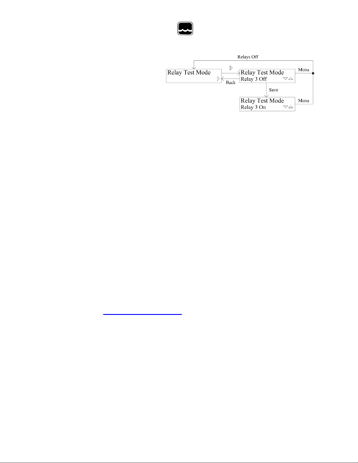
Relay Test M ode:
To manually test relay ope ration, press the RIGHT arrow.
Use UP and DOWN to select t he relay number to test.
When a relay is selected, press SAVE t o toggle the re lay between On and Off. Press
Display or Ba ck to exit test mode, the relays will tur n off upon exit.
XI. Data Logger Option
A factory option for the PC320 is an intern al data logger which records a historical
record of wa ter flow, and r ecords the exact time of each relay pulse. C ha nne l o ne of
the data logger records f low and channel two records relay events. A special sof tware
package allows the programming of the logger and the download of recorded flow and
relay data. This softwar e differs from other Global Water data logger software in the
way it proce sses the relay data. Softwar e such as Global Logger II will work with the
PC320 data logger option but som e relay information will no t be seen. The da ta lo gge r
is factory calibrated a nd should not need to be recalibrated again. Should you need to
recalibrate the logger, consult the Data Logger Option manual.
XII. Technical Support
a. Call Global Water for tec h support: 800-876-1172 or 979-690-5560
(many problems can be solved over the phone). Fax: 979-690-0440 or Email:
When calling for tech support, please have the following information
ready;
globalw@globalw.com.
1. Model #.
2. Unit serial number.
3. P.O.# the equipment w as pur c ha sed o n.
4. Our sales numbe r or the invoice number.
5. Repair instructions and/or specific probl ems relating to the
product.
- 17 -

b. In the event that the equipm ent needs to be returned to the f actory for any
Warranty
a. Global Water Instrumentation, Inc. warrants that its products a re free
b. The warranty begins on the date of your invoice.
Global Water
800-876-1172 • globalw.com
Be prepared to describe the problem you are experiencing including
specific deta ils of the appl ica ti on, ins tal la ti on, an d any a dditional
pertinent inf ormation.
reason, ple ase call to ob tain an RMA# (Return Material Authori zation).
Do not return items without an RMA# displayed on the outside of the
package.
Clean and decontaminate the PC320 if necessary.
Include a written statement describing the problems.
Send the package with shipping prepaid to our factory address. Insur e
your shipment, Global Water’s warranty does not cover damage incurred
during transi t.
from defects in material and workmanship under nor mal use and
service for a period of one year from date of shipm ent from factory.
Global Water’ s ob lig ati o ns under this warranty are limited to, at
Global Water ’s option: (I) replacing or (II) repairing; any products
determined to be defective. In no case shall Global Water’s liab ility
exceed the prod uc ts or igi na l pur c has e pr ice . This warra nty does not
apply to any equipment that has been repa i re d or alte re d, exce pt by
Global Water Instrumentation, Inc., or which has been subject to
misuse, negligence or a ccident. It is e xpressly agreed that this
warranty will be in lieu of a ll warranties of fitness and in lieu of the
warranty of merchantability.
- 18 -

Global Water
800-876-1172 • globalw.com
XIII. Appendix A: Terminal Strip Diagram
POWER IN:
V+ 12VDC or 18-24VDC Input
V+ 12VDC or 18-24VDC Input
12VDC Input: SW7 OFF, SW8 ON
18-24VDC Input: SW7 ON, SW8 OFF
GND Power Supply and System Ground
GND Power Supply and System Ground
SENSOR IN:
V+ Sensor Power
12VDC Sensor Power: SW1 ON, SW2 OFF
18-24VDC Sensor Power: SW1 OFF, SW2 ON
(18VDC Power Input Only)
IN Sensor Input
Sensor Power Cont inuous: SW3 ON
Sensor Power Switched: SW3 OFF (Power Saving Mode)
4-20mA Sensors: SW4 ON, SW5 ON
0-5VDC Sensors: SW4 OFF, SW5 ON
0-1VDC Sensors: SW4 OFF, SW5 OFF
4-20mA:
OUT 4-20mA Output
GND Power Supply and System Ground, 4-20mA return Path
RELAY 1-4:
- 19 -
 Loading...