

Page 1

INSTRUCTION MANUAL
IM125
RJA & RJDS Quick-Set
INSTALLATION, OPERATION AND MAINTENANCE INSTRUCTIONS
™
Page 2

WARNING
WARNING
WARNING
WARNING
WARNING
T C
Section 1 – Installing a New Shallow Well Pump ................................................................................................................ 4
Section 2 – Installing or Replacing a Shallow Well Pump ..................................................................................................4
Section 3 – Deep Well Installations - Introduction ............................................................................................................. 6
Section 4 – Installing a New Deep Well ...............................................................................................................................6
Section 5 – Installing or Replacing a Deep Well Pump .....................................................................................................7
Section 6 – Maintenance .......................................................................................................................................................9
Section 7 – Pressure Tanks and Piping ...............................................................................................................................10
Section 8 – Troubleshooting Checklist ..............................................................................................................................11
Section 9 – Repair Parts .......................................................................................................................................................14
SAFETY INSTRUCTIONS
TO AVOID SERIOUS OR FATAL PERSONAL INJURY
OR MAJOR PROPERTY DAMAGE, READ AND
FOLLOW ALL SAFETY INSTRUCTIONS IN MANUAL
AND ON PUMP.
THIS MANUAL IS INTENDED TO ASSIST IN THE INSTALLATION AND OPERATION OF THIS UNIT AND
MUST BE KEPT WITH THE PUMP.
This is a SAFETY ALERT SYMBOL.
When you see this symbol on the pump
or in the manual, look for one of the
following signal words and be alert to the
potential for personal injury or property
damage.
DANGER
Warns of hazards that WILL cause serious
personal injury, death or major property
damage.
WARNING
Warns of hazards that CAN cause serious
personal injury, death or major property
damage.
CAUTION
Warns of hazards that CAN cause personal
injury or property damage.
NOTICE: INDICATES SPECIAL INSTRUCTIONS
WHICH ARE VERY IMPORTANT AND MUST BE
FOLLOWED.
THOROUGHLY REVIEW ALL INSTRUCTIONS
AND WARNINGS PRIOR TO PERFORMING ANY
WORK ON THIS PUMP.
MAINTAIN ALL SAFETY DECALS.
Important notice: Read safety instructions before proceeding with
any wiring
All electrical work must be performed
by a qualified technician. Always follow
the National Electrical Code (NEC), or the Canadian
Electrical Code, as well as all local, state and provincial
codes. Code questions should be directed to your local
electrical inspector. Failure to follow electrical codes and
OSHA safety standards may result in personal injury or
equipment damage. Failure to follow manufacturer’s
installation instructions may result in electrical shock,
fire hazard, personal injury or death, damaged equipment, provide unsatisfactory performance, and may void
manufacturer’s warranty.
Standard units are not designed for use in
swimming pools, open bodies of water,
hazardous liquids, or where flammable gases exist. Well
must be vented per local codes. See specific pump catalog
bulletins or pump nameplate for all agency Listings.
Disconnect and lockout electrical power
before installing or servicing any electrical
equipment. Many pumps are equipped with automatic
thermal overload protection which may allow an overheated pump to restart unexpectedly.
Never over pressurize the tank, piping or
system to a pressure higher than the tank's
maximum pressure rating. This will damage the tank,
voids the warranty and may create a serious hazard.
Protect tanks from excessive moisture and
spray as it will cause the tank to rust and
may create a hazard. See tank warning labels and IOM
for more information.
PRE-INSTALLATION CHECK
WARNING
codes and plumbing requirements. Be sure your well is the
required minimum distance away from sources of contamination such as cistern, septic tank field, field tile, etc.
CAUTION
your local Health Department for testing procedures.
CAUTION
prevent contamination and pump damage.
NOTICE
freezing temperatures exist.
2
Before you start on a new residential water
well system, check state and local well
Always disinfect the well and test well
water for purity before using. Check with
Make sure your well is covered with a
pitless adapter or sanitary well seal to
Always drain the pump and tank during
extended periods of non-use when below
Page 3

TOOLS AND MATERIAL REQUIRED
1. Two adjustable pipe wrenches
2. Open end adjustable wrench
3. Screwdriver
4. Measuring tape
5. Pipe clamp(s) (to hold pipe during installation).
6. Drive point system only - a slip over drive weight pounder
(to pound in drive point).
7. Galvanized pipe - a non-toxic pipe sealing compound or
type to insure air-tight joints.
8. Plastic pipe - a non-toxic cement or tape to insure air-tight
joints
Motor Voltage Change
The A.O. Smith and Emerson jet pump motors both have a
voltage change switch for ease of changing operating
voltage from low (115 volt) to high (230 volt) operation. The
A.O. Smith switch must be pulled out, moved and pushed in.
The Emerson switch is a toggle that can be changed using a
pen tip or a small screwdriver. The Emerson motor switch is
marked 115 and 230.
CAUTION
them to a 230 volt power supply will damage the motor
windings, and/or the capacitor, and/or the overload protector. This damage is easily diagnosed and will not be covered
as a warranty failure.
Motors of ¾ hp and larger are factory wired for 230 volts.
Connecting them to a 115 volt power supply without changing the voltage switch will result in poor performance, noisy
operation and overload tripping due to high heat.
It is an industry standard procedure to ship
½ hp motors wired at 115 volts, connecting
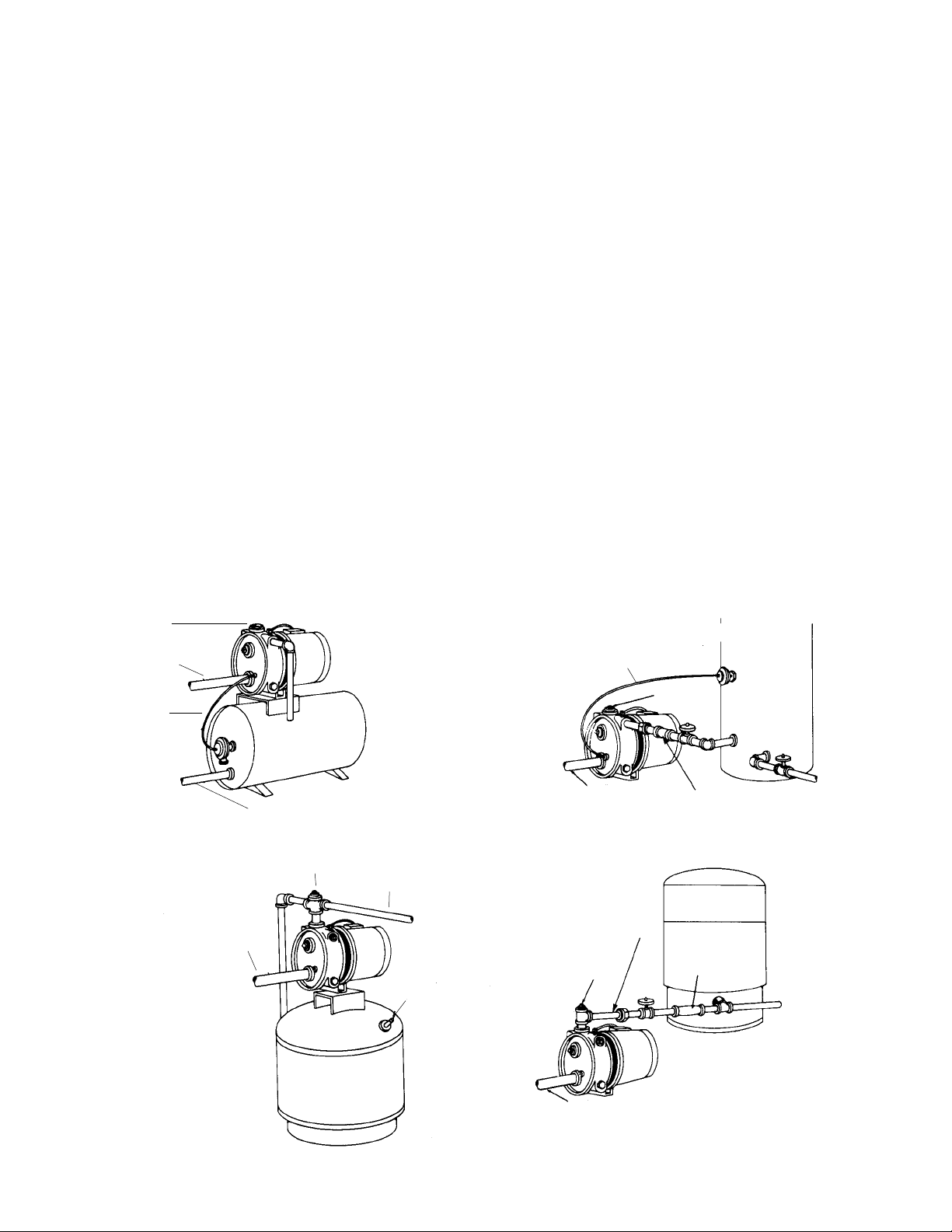
SHALLOW WELL SYSTEMS
Red Jacket convertible jet
pumps can be adapted to
the following shallow well
systems:
Fig. 1A - horizontally to a
shallow well.
Fig. 1B - horizontally to
drive point.
FIGURE 1
DEEP WELL SYSTEMS
Red Jacket convertible jet
pumps can be adapted to the
following deep well systems:
Fig. 1C - horizontally to a 3"
or 4" double well seal.
Fig. 1D - horizontally to a
vertical 2" well adapter.
JET PUMP SYSTEMS
TABLE A — WIRING CHART RECOMMENDED WIRE AND FUSE SIZES
Distance in Ft. – Meter to Motor
Motor HP Voltage
1
⁄3 115 15 14 14 12 10 8 8
½ 115 15 14 14 10 8 8 8
½ 230 15 14 14 14 14 14 12
¾ 115 20 12 12 10 8 6 4
¾ 230 15 14 14 14 14 12 10
1 115 20 12 12 8 6 6 4
1 230 15 14 14 14 12 12 10
Branch Fuse
Rat. Amps
0-50' 51'-100' 101'-200' 201'-300' 301'-400' 401'-500'
Wire Size
3
Page 4

S
I N S
W
TEE
UNION
SUCTION DROP PIPE
WELL CASING
SHALLOW
WELL
SYSTEM
FOOT
VALVE
CHECK VALVE
WELL
ADAPTER
TEE
HEAVY DUTY
DRIVE PIPE COUPLING
DRIVE PIPE
OR SUCTION PIPE
DRIVE
POINT
SYSTEM
WELL OR
SAND POINT
2' MINIMUM
FIGURE 2
(tape or cement on plastic pipe) to facilitate making air
tight joints.
Step 3. To install the suction drop pipe in an existing shallow
well, support the pipe with a pipe holder or clamp. Fill each
pipe section with water when lowering, constantly observing
for leaks. Install the foot valve no closer than 2' from the bottom of the well to prevent sand, mud, or other foreign matter
from clogging the intake.
Step 4. Horizontal piping from the pump to the well should
be as short as possible to avoid increased friction losses.
For most efficient operation, the suction pipe should not
be smaller than the suction tapping on the pump. Table B
shows the correct pipe sizes for horizontal runs. If the pump
is being installed offset from the well, the piping should pitch
upward from the well to the pump about 1" for each 10' of
pipe to prevent air pockets in the line. Plumbing should be
below the frostline or otherwise protected from freezing.
Step 5. Attach appropriate tee or adapter at the junction of
the horizontal and vertical suction pipes as shown in Figure
2. The tee can be used to clean the well.
Step 6. It is important to clean the well of sand and muddy
water to prevent damaging your pump. Clean the well by inserting a garden hose down the well pipe and surging water
into the well. Wait until the water flowing out of the suction
pipe is clean.
If you are replacing an existing shallow well pump, refer to
Section 2.
NOTICE
Fittings for a shallow well installation such as
foot valves, well adapters, couplings, unions and piping
must be purchased separately. Your Red Jacket Jet pump
can be adapted horizontally to shallow well or drive
point systems. See Figure 2.
INITIAL PIPING IN A SHALLOW WELL
Step 1. To insure continual priming on a shallow well system, (Left-Figure 2) a foot valve must be installed. On a drive
point system, (Right-Figure 2) a check valve must be installed
as close as possible to the pump. Examine the foot valve or
check valve to see that it is clean and seated properly.
Step 2. Inspect the piping to be sure it is free of obstructions such as dirt. Galvanized iron pipe is often used, but
plastic pipe can be used if allowable under existing state
and local plumbing codes. Use either non-toxic pipe sealing
compound or tape on male thread joints of galvanized pipe
S
I R
S W P
TYPICAL INSTALLATIONS
In order to eliminate unnecessary down time in your water
supply, take a few minutes before you start the installation to
study your existing piping system and the typical Red Jacket
system layouts shown in Figure 3. In some cases additional
piping may be necessary. If you are replacing a conventional
pressure tank with a pre-charged air tank, the air volume control line is not necessary. Note in the illustrations how your
Red Jacket pump may be piped from either the top or side.
Step 1. FOR YOUR SAFETY turn off the electrical power supply at the service entrance before connecting or disconnecting any wiring to the pump to avoid any
possible electrical shock hazard.
Step 2. Drain the holding tank. Also disconnect the suction
pipe, the service line, and if necessary, the air volume control
line. Remove old pump.
WARNING
TABLE B — PIPE SIZES FOR HORIZONTAL RUNS
Pump Suction
Size
½ & ¾ HP 1¼ 1½ 1½ 2 2 2 2
1 HP 1½ 2 2 2½ 2½ 2½ 2½
NOTE: As the horizontal distance and the pipe size increase, the length of time to prime increases.
4
10-50 ft. 51-75 ft. 76-100 ft. 101-150 ft. 151-200 ft. 210-250 ft. 251-300 ft.
Page 5
Step 3. Place the jet pump on a level, solid foundation. If
you are also replacing the existing pressure tank, refer to
Section 7 in this manual.
Step 4. Connect the suction pipe, the service line, and if
necessary, the air volume control line. Use either non-toxic
pipe sealing compound or tape on male thread joints of
galvanized pipe (tape or cement on plastic pipe) to facilitate
making air tight joints.
Step 5. Wire the motor.
The Red Jacket convertible jet pump is wired to the pressure
switch. The pressure switch must be grounded in compliance
with the National Electrical Code and state and local codes
and ordinances. It is mandatory that a ground connection be
made using a conductor or appropriate metal underground
water pipe or a ground lead in the service panel.
Step 6. Prime the pump.
A. Remove top priming plug.
B. Open faucets on downstream side of the pressure
tank so air can be purged from the system while priming.
C. Pour water into the pump case until it flows freely out
of the priming hole without air bubbles.
D. Replace priming plug, leaving the plug loose enough
to allow the air in the case to bleed off. Turn power
on. Start pump. Water should be pumped in a few
minutes depending on depth to water and horizontal
piping length.
E. After water is pumped, close faucets. Sufficient pres-
sure should build up and shut the pump off.
Direct wiring instructions can be found by following the wiring instructions on the inside cover of your pressure switch.
SHALLOW WELL JET PUMP SYSTEM LAYOUTS
PRIME HERE
SUCTION PIPE
AIR VOLUME
CONTROL
LINE
SERVICE LINE
PUMP MOUNTED ON
GALVANIZED TANK
PRIME HERE
SERVICE LINE
Step 7. Disinfect the well using a cup of household bleach.
Let the water stand for 3 to 4 hours. Test it for purity with the
local Health Department before using.
Step 8. To assure continued primability, tighten all plugs to
prevent air leaks.
AIR VOLUME
CONTROL LINE
PRIME HERE
SUCTION PIPE
SERVICE LINE
SIDE DISCHARGE TO
GALVANIZED TANK
PUMP MOUNTED
ON PRE-CHARGED
AIR TANK
TOP DISCHARGE
FIGURE 3
SUCTION PIPE
AIR CHARGING
VALVE
SERVICE LINE
PRIME HERE
SUCTION
PIPE
ISOLATOR
HOSE
TOP DISCHARGE TO
PRE-CHARGED AIR TANK
5
Page 6
POUR WATER
INTO PUMP
CASE
PRIMING PLUG
PRESSURE SWITCH
Red Jacket convertible jet pumps can be adapted to the following deep well systems: 1) horizontally to a 3" or 4" double
pipe well seal (Figure 5); 2) horizontally to a vertical 2" well
adapter (Figure 6).
SUCTION
PIPE
SERVICE
LINE
FIGURE 4
INSTALLATION TIP
The pressure switch supplied with ½ HP Jet Pumps is preset
to 20-40 PSI (pump turns on when system pressure drops
to 20 PSI - pump turns off when system pressure reaches 40
PSI). ¾ HP and 1 HP Jet Pumps are preset at 30 - 50 PSI.
If adjustments are necessary to fit your system needs,
follow the adjustment instructions on the inside cover of the
pressure switch. If you are using a precharged pressure tank
with your system, be sure that the empty tank pressure is
2 PSI lower than the cut in pressure setting of your pressure
switch. (See Section 7 - page 10)
S
D W I I
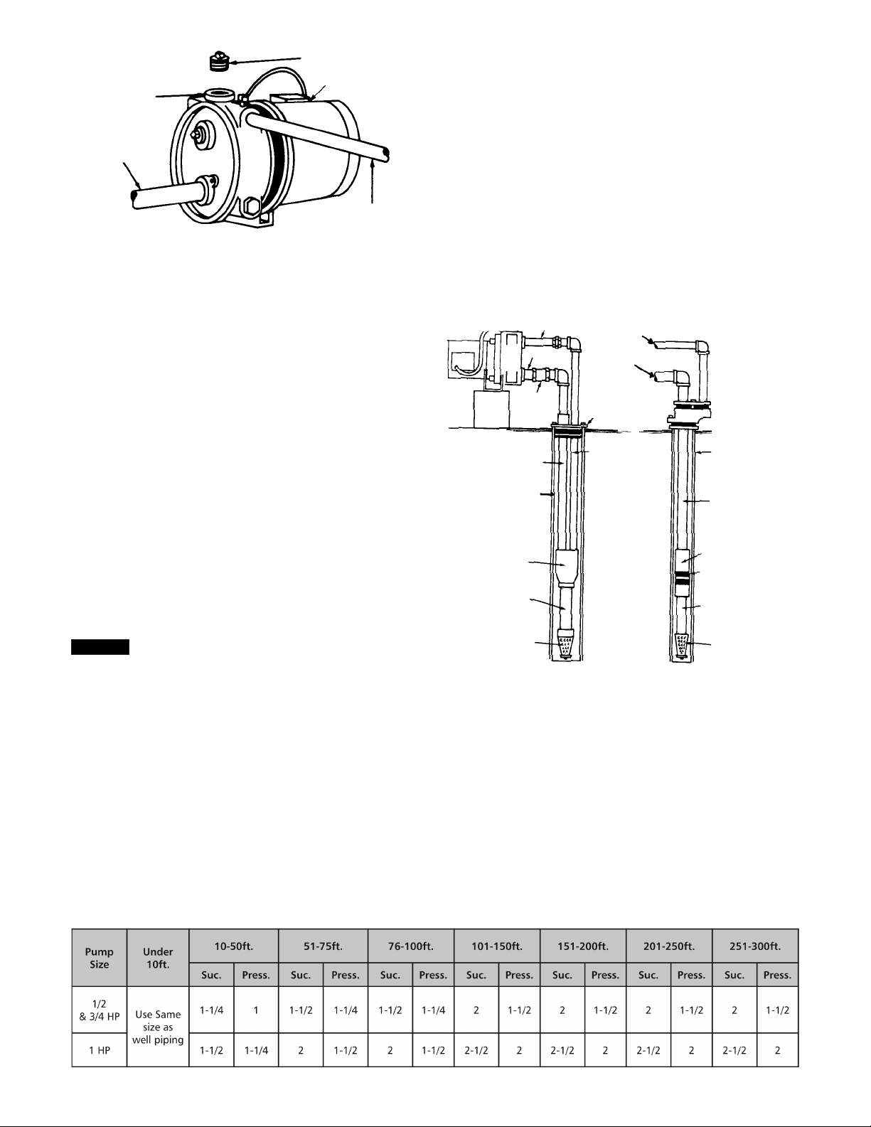
INITIAL PIPING IN A DEEP WELL
Step 1. On a deep well system similar to Figure 5, a foot
valve should be attached to a tail pipe ( a 5' to 10' length of
pipe attached to the bottom of the injector). The suction pipe
is larger than the drive pipe and should be the same size
at the tapped opening in the jet pump (1¼"). On deep well
systems similar to Figure 6, a 2" single pipe injector is used.
In this installation the well casing serves as the drive pipe.
SUCTION PIPE
WELL CASING
3" OR 4"
EJECTOR
TAIL PIPE (5")
DRIVE PIPE
SUCTION
PIPE
CHECK
VALVE
DRIVE PIPE
SUCTION
PIPE
WELL SEAL
DRIVE PIPE
2" WELL
ADAPTER FLANGE
WELL CASING
SUCTION PIPE
PACKER ASSEMBLY
2" SINGLE PIPE
EJECTOR
TAIL PIPE (5' TO 10')
NOTICE
In order to install the Red Jacket Convertible
Jet Pump in a deep well system, a Red Jacket
deep well conversion kit must be purchased. The kit
contains a deep-well plug, pressure gauge and a manual
regulator. Kit Order No. is 1441315
S
I N D W
If you are replacing an existing deep well pump, refer to
Section 5.
TABLE C — PIPE SIZES FOR HORIZONTAL RUNS
FOOT VALVE
FOOT VALVE
FIGURE 5 FIGURE 6
Step 2. Before installation, single pipe injectors, packers,
should be soaked in water for at least two hours so the leathers seat properly. Special turned couplings, order no. 64655,
are required for 2" injectors.
NOTE: AS the horizontal distance and the pipe size increase, the length of time to prime increases.
6
Page 7

Step 3. To install the pipes, use either non-toxic sealing
compound or tape on male thread joints to facilitate making air tight joints. Pipe should be supported with a pipe
holder or clamp. Fill each pipe section with water when
lowering, constantly observing for leaks. Lower until injector is submerged at least 5' below the lowest anticipated
water level. The foot valve should be at least 2' from the
bottom of the well.
Step 4. If you are using 2” single pipe injector ( Figure 6),
the packer assembly may have to be forced into the well
casing as it must be tight against both the casing and the
suction pipe.
Step 5. An appropriate well seal or adapter should be
installed at the top of the well casing and two bolts drawn
up until the rubber gaskets are tight against both the well
casing and the pipes.
Step 6. Horizontal piping from the well to the pump
should be as short as possible to avoid increased friction
losses. Table C shows the correct pipe sizes for horizontal
runs. Pipe should pitch upward from the well to the pump
about 1” for each 10’ of pipe to prevent air pockets in the
line. Plumbing should be below the frostline or otherwise
protected from freezing.
Step 7. It is important to clean the well of sand and muddy
water to prevent damaging your pump. Clean the well by
inserting a garden hose down the well pipe and surging
water into the well. Wait until the water flowing out of the
suction pipe is clean.
S
SUCTION
PIPE
DRIVE PIPE
REPLACEMENT PIP-
ING SYSTEM
FIGURE 8
TYPICAL INSTALLATIONS
In order to eliminate unnecessary down time in your water
supply, take a few minutes before you start the installation
to study your existing piping system and the typical JET
pump system layouts shown in Figure 10. In some cases
additional piping may be necessary. Be sure to identify: 1)
suction pipe and drive pipe; 2) service line from the pump
to the pressure tank or residence; 3) the air volume control
line from the pump to the pressure tank. If you are replacing
a conventional pressure tank with a pre-charged air tank, the
air volume control line is not necessary.
I R
D W P
Your Red Jacket convertible jet pump can replace most
deep well pumps with piping adjustments.
On Red Jacket jet pumps the smaller top pipe is the drive
pipe and bottom larger pipe is the suction pipe (Figure7.)
In certain installations, the larger suction pipe may be at the
top and the smaller drive pipe at the bottom of the existing
pump (Figure 8.) On these installations, a crossover adapter reversing the drive and suction pipes can be assembled
with nipples, elbows, couplings and pipe (Figure 9.)
DRIVE
PIPE
SUCTION
PIPE
JET PUMP PIPING
SYSTEM
If you want to use a top discharge system, a “T” manual
regulating valve is necessary.
PUMP CASE
PIPE
SUCTION
DRIVE PIPE
CROSS OVER
ADAPTER
SUCTION PIPE
ADDITIONAL PIPING
REQUIRED
1. 1" x 4" Galvanized Nipple
2. 1" x 90° Elbow (3 required)
3. 1" x 6" Galvanized Nipple (2 required)
4. 1 - 1/4" x 6" Galvanized Nipple
5. 1 - 1/4 " Coupling
FIGURE 7
FIGURE 9
7
Page 8

INSTALLATION STEPS
WARNING
Step 1. FOR YOUR SAFETY turn off electrical
power supply at the service entrance before connecting
or disconnecting any wiring to the pump to avoid any
possible electrical shock hazard.
Step 2. Drain the holding tank. Also disconnect the drive
pipe and the suction pipe, the service line, and if necessary,
the volume control line. Remove old pump.
Step 3. Place the jet pump on a level, solid foundation. If
you are also replacing the existing pressure tank, refer to
Section 7 in this manual.
Step 4. Connect the drive pipe and suction pipe, the service
line and, if necessary, the air volume control line. Use either
non-toxic pipe sealing compound or tape on male thread
joints of galvanized pipe (tape or cement on plastic pipe) to
facilitate making air tight joints.
Step 5. Wire the motor.
The Red Jacket convertible jet pump is wired to the pressure
switch. The pressure switch must be grounded in compliance
with the National Electrical Code and state and local codes
and ordinances. It is mandatory that a ground connection be
made using a conductor or appropriate metal underground
water pipe or a ground lead in the service panel.
WARNING
When installing a pump with a 3-prong
grounding plug do not remove round grounding prong
since it must be plugged into a grounded receptacle to
assure proper grounding.
Direct wiring instructions can be found on the inside cover of
your pressure switch.
Step 6. Prime the Pump
A. Remove the manual regulator.
B. Pour water into the pump case until it flows freely out
of the priming hole without air bubbles.
C. Turn the regulator adjusting screw counter-clockwise
until stem travel stops, or regulator poppet is near
valve bushing end. Replace regulator.
D. Turn the adjusting screw in a clockwise direction until
it is all the way in.
E. Open faucets on the downstream side of the pressure
tank to bleed off air.
F. Turn power on. Start pump. The pump should start
showing pressure on the pressure gauge.
G. To adjust the regulator, slowly turn the adjusting screw
in a counter-clockwise direction until the pressure
gauge fluctuates rapidly or the pump becomes noisy.
At this point, turn the screw clockwise until gauge
pressure holds steady.
H. Close all faucets on the downstream side. Sufficient
pressure should build up and shut the pump off.
PRESSURE GAUGE
SUCTION PIPE
AIR VOLUME CONTROL LINE
"T" MANUAL REGU-
LATING VALVE
DRIVE PIPE
SUCTION PIPE
DRIVE PIPE
SERVICE LINE
PRIME HERE
DEEP WELL JET PUMP SYSTEM LAYOUTS
MANUAL REGULATOR
SERVICE LINE
AIR CHARGING
VALVE
MANUAL REGULATOR
DRIVE PIPE
SUCTION PIPE
MANUAL REGULATOR
"T" MANUAL
REGULATING
VALVE
DRIVE PIPE
AIR VOLUME
CONTROL LINE
PRIME HERE
SERVICE LINE
SERVICE LINE
PRIME HERE
ISOLATOR
HOSE
SUCTION PIPE
FIGURE 10
8
Page 9

Step 7. Disinfect the well using a cup of household bleach.
Let the water stand for a 3-4 hours. Test it for purity with the
local Health Department before using.
Step 8. To assure continued primability, tighten all plugs to
prevent air leaks.
S
M
Lubrication:
A. The pump requires no lubrication.
B. For the electric motor, refer to instructions provided by
the motor manufacturer.
SEAL REPLACEMENT
Seal Removal:
1. Disconnect electrical service to the pump.
2. Relieve system pressure by opening a faucet or drain
valve until water stops flowing.
3. Disconnect pressure switch tubing at the barbed fitting
on the pump case. If tubing does not slide off barbed
fitting easily, cut it as close to the fitting as possible.
4. Remove the four cap screws which hold the pump seal
plate and motor to the pump case. Piping need not be
disturbed.
5. Remove the pumping assembly, as one piece, (motor,
seal plate, diffuser, and impeller) by carefully prying
them apart from the pump case. Exercise care so as not
to damage the impeller.
6. Remove the diffuser from the seal plate exposing the
impeller.
7. Insert a regular slotted screwdriver into the slot in the mo-
tor shaft end at the impeller center.
8. While holding the motor shaft with the screwdriver, un-
screw the impeller by turning counter-clockwise.
9. Slide rotating part of seal assembly from shaft (Figure 11).
Separate seal plate from motor.
10. Remove stationary part of seal assembly (including rubber seal boot) from seal plate.
New Seal Installation:
1. Clean polished surface of stationary seal with a clean
cloth.
2. Wet the outer edge of the rubber seal boot with a soap
solution.
3. Insert rubber seal boot and ceramic seal (polished side
exposed) into seal plate. Make a cardboard washer to
cover the ceramic seal surface to be used while pressing
seal into position. Cardboard washer is used to avoid
scratching ceramic surface. Discard cardboard washer
after ceramic seal installation. (Figure 11).
4. Reposition seal plate onto motor and slide rotating seal
assembly onto motor shaft with carbon sealing face first
until rubber end ring slides over shaft shoulder.
5. Screw impeller clockwise onto motor shaft using screwdriver in shaft end slot to hold the shaft.
6. Reattach diffuser to seal plate and carefully reposition the
pumping assembly to the pump case. Attach with the
four cap screws.
7. Connect the pressure tubing by pressing on to barb fitting on pump case until tubing shoulders against stop
edge of fitting. If tubing was cut off, carefully remove
excess tubing from barb fitting with a knife, taking care
not to scratch the fitting.
Motor Removal
1. Follow Steps 1-10 of “Seal Removal.”
Motor Replacement:
1. Follow Steps 1-7 of “New Seal Installation.”
FIGURE 11
CASE BOLT
MOTOR SHAFT
SEAL PLATE
O-RING
SEAL BOOT
ROTATING SEAL
CERAMIC SEAL
IMPELLER
DIFFUSER
O-RING
9
Page 10

S P T
P
S P T
When a pump is used with a standard pressure tank, it must
be connected to the tank using standard fittings. A rubber
isolator hose should be connected between the pump and
the tank to reduce noise and vibration transmission. Set
the tank on bricks to avoid condensation beneath the tank.
Install a union and a gate valve between the pump and tank
for servicing. Install an air volume control in the tank tapping
and connect ¼" tubing to the pump. (Figure 12.)
AIR VOLUME CONTROL
ISOLATOR HOSE
AIR VOLUME
CONTROL
CONNECTION
UNION
GATE VALVE
STD. GALVANIZED
PRESSURE TANK
VALVE
R S T W
P-C A T
Many times a defective steel tank must be replaced with a
pre-charged air tank to provide effective system protection.
Figure 13 should be followed for correct connection to the
system.
Because a pre-charged air tank is precharged with air, it will
always occupy less space than a standard tank for similar
amounts of pressurized water. Be sure to plug the air port on
a jet pump, as it is no longer necessary to supply air to the
tank.
A P-C T T
S R
Pre-charged tanks are shipped with a standard precharge of
38 PSI. The precharge should be adjusted according to the
installation instructions packed with the tank.
PRE-CHARGED
AIR TANK
"T" MANUAL
REGULATING
VALVE
DRIVE PIPE
GATE VALVE
ISOLATOR
UNION
HOSE SERVICE
LINE
TO SYSTEM
SHUT-OFF
VALVE
DRAIN
STANDARD PRESSURE TANK
RELIEF
VALVE
CENTRIPRO
TANK
SUCTION
PIPE
PUMP STAND
FIGURE 14
SUCTION
PRESSURE
SWITCH
PUMP STAND
DRAIN
OPTIONAL
LOCATION
FOR PRESSURE
PIPE
TO SYSTEM
SWITCH
PRE-CHARGED AIR TANK
FIGURE 13FIGURE 12
SHUT-OFF VALVE
SUCTION PIPE
CENTRIPRO
TANK
UNION
FIGURE 15
10
Page 11

elbuorTfoseuaC kcehCotwoH tcerroCotwoH
esuFnwolB.1KOsiesuffieesotkcehC reporpfoesufhtiwecalper,nwolbfI
)AelbaTeeS(ezis
fforewoP.2.tiucricemasnosthgilyrTynapmocrewoptcatnoC
gniriwtcerrocniro,nekorb,esooL.3 kcehC.etalprevoctiudnocevomeR
tahteeS.margaidtsniagatiucricgniriw
ontahtdnathgiterasnoitcennoclla
nrowfoesuacebtsixestiucrictrohs
.cte,eriwdessorc,noitalusni
repsastiucrictcerrocniynaeriweR
.margaidgniriw
hctiwserusserpytluaF.4 hctiwsenim
axE.gnitteshctiwskcehC
.raewevissecxerotridrofstcatnoc
stcatnocnaelC.sgnitteshctiwstsujdA
.ytridfihtolcyremehtiw
.deggulphctiwserusserpotgnibuT.5 .tihguorhtwolbdnagnibutevomeR.deggulpfiecalperronaelC
laeSrorellepmI.6 rellepminrutotyrtotrevirdwercsesU
.rotomro
laesevomer,nrutt'nowrellepmifI
rognidnibfoecruosetacoldnagnisuoh
.pmupnruter
rotomevitcefeD.7 dna(6urht1spetsgnikcehcretfA
sirotom)KOsigniriwlanretxe
.evitc
efed
.ytnarrawrednullitsfipmupnruteR
elbuorTfoesuaC kcehCotwoH tcerroCotwoH
.yltcerrrocnideriwrotoM.1.margaidgniriwrotomkcehC repsaegatlovreporproftcennoceR
.margaedgniriw
.noitalitnevetauqedanI.2 sipmuperehwerutarepmetriakcehC
yamdaolrevo,.F°001revofI.detacol
.taehlanretxenognippirteb
evomronoitalitnevetauqedaedivorP
.pmup
.yrevilederusserpwoldegnolorP.3
).smetsysrelknirpssahcuS(
wolyrevtanoitareposuounitnoC
nodaolrevoyvaehsecalperusserp
daolrevoesuacnacsihT.pmup
.pirtotnoi
tcetorp
evlaVltnavresordyHtekcaJdeRllatsnI
ecuderotelttortdnaenilegrahcsidno
.erusserpesaercniotdnawolf
.egatloveniltcerrocnI.4 .hctiwserusserpotegatlovenilkcehCdednemmocerrednuegatlovfI
morfgniriwfoeziskcehc,muminim
tcatnoc,KOfI.ytreporpnohctiwsniam
.ynapmocrewop
S
T C
A -- PUMP WILL NOT START
turn off power before servicing pump
WARNING
B -- MOTOR OVERHEATS AND OVERLOAD TRIPS OUT
turn off power before servicing pump
WARNING
11
Page 12

elbuorTfoesuaC kcehCotwoH tcerroCotwoH
rognitteshctiwserusserpgnorW.1
"tfird"gnittes
stuhspmupfI.gnitteshctiwsrewoL
.elbuortehtsawsiht,ffo
.gnittesnepoerpothctiwstsujdA
.hctiwserusserpevitcefeD.2 tcatnochctiwsdesuacevahyamgnicrA
.noitisopdesolcnirehtegot"dlew"ot
fostraprehtodnastniopenimaxE
.stcefedrofhctiws
.evitcefedfihctiwsecalpeR
.deggulphctiwserusserpotgnibuT.3 .tihguorhtwolbdnagnibutevomeR.deggulpfiecalperronaelC
.emirpfossoL.4 kceh
c,dereviledsiretawonnehW
.gnipipllewdnapmupfoemirp
.yrassecenfiemirpeR
.levelllewwoL.5 ecnamrofreptsniagahtpedllewkcehC
dnapmuperusekamotscitsiretcarahc
.dezisylreporperarotcejni
.rotcejeropmupecalper,dezisrednufI
.rotcejerorotcejnideggulP.6.tcepsnidnaevomeR.ytridfillatsnierdnanaelC
elbuorTfoesuaC kcehCotwoH tcerroCotwoH
.knaterusserpnikaeL.1 ecafruseritneotertawypaosylppA
ria,raeppaselbbubfI.enilretawevoba
.knatmorfgnikaelsi
.knatecalperroskaelriapeR
.lortnocemulovriaevitcefeD.2 .knatdeggolretawaotdaellliwsihT
.ylreporpgnitareposilortnocerusekaM
rofenimaxednaevomer,tonfI
.gniggulp
.lortnocevitcefedecalperronaelC
.hctiwserusserpytluaF.3 hctiwsenimaxE.gnitteshctiwskcehC
.raewevissecxerotridroftcatnoc
tcatnocnaelC.sgni
tteshctiwstsujdA
.ytridfihtolcyremehtiw
.metsysfoedisegrahcsidnokaeL.4 gnibmulpniserutxifllaerusekaM
llakcehcnehT.ffotuhserametsys
.skaelrof)skcocllabyllaicepse(stinu
.gninnurretawfoesionrofnetsiL
.yrassecensaskaelriapeR
.metsysfoedisnoitcusnokaeL.5 erusserpllatsni,stinullewwollahsnO
llewpeednO.edisnoitcusnoeguag
ehtoteguagerusserpahcatta,smetsys
.evlavenilegrahcsidehtesolC.pmup
riaropmupelcycibagnisu,nehT
isp0
3tuobaylppa,rosserpmoc
metsysehtfI.metsysehtoterusserp
ehtnehwerusserpsihtdlohtonlliw
kaelasiereht,ffotuhssirosserpmoc
.edisnoitcusehtno
snoitcennocdnuorgevobaerusekaM
fI.tsettaepernehT.thgitera
.kaelriaperdnagnipipllup,yrassecen
.evlavtoofnikaeL.6 .evlavtoofenimaxednagnipiplluP .evlavevitcefedecalperroriapeR
C -- PUMP WILL NOT SHUT OFF
turn off power before servicing pump
WARNING
D -- PUMP STARTS AND STOPS TOO OFTEN
turn off power before servicing pump
WARNING
12
Page 13

elbuorTfoesuaC kcehCotwoH tcerroCotwoH
.demirpyletelpmocnimetsyS.1 kcehc,dereviledsiretawonnehW
.gnipipllewdnapmupfoemirp
.yrassecenfiemirpeR
.enilnoitcusnikcolriA.2 llewneewtebgnipiplatnozirohkcehC
drawpuhctiptonseodtifI.pmupdna
yamkcolriana,pmupotllewmorf
.mrof
.kcolriaetanimileotgnipipegnarraeR
.gnipipdezisrednU.3 gnipipegrahcsideht,wolsimetsysfI
ebyamsenilgnibmulpro/dna
.dezisrednu
llatsnirognipipdezisrednuecalpeR
.yticapacrehgihhtiwp
mup
.gnibutrolortnocemulovrianikaeL.4 tagnibutlortnocemulovriatcennocsiD
yticapacfI.elohgulpdnapmup
fognibutehtnistsixekaela,sesaercni
.lortnoc
filortnocecalperdnasgnittifllanethgiT
.yrassecen
rokcutsevlavgnitalugererusserP.5
)ylnollewpeeD(.tesyltcerrocni
rofevlavtcepsnI.gnittesevlavkcehC
.stcefed
filortnocecalperro,naelc,teseR
.yrassecen
.metsysfoedisnoitcusnokaeL.6 erusserpllatsni,stinullewwollahsnO
llewpeednO.
edisnoitcusnoeguag
ehtoteguagerusserpahcatta,smetsys
.evlavenilegrahcsidehtesolC.pmup
riaropmupelcycibagnisu,nehT
isp03tuobaylppa,rosserpmoc
metsysehtfI.metsysehtoterusserp
ehtnehwerusserpsihtdlohtonlliw
kaelasiereht,ffotuhssirosserpmoc
.edisnoitcusehtno
snoitcennocdnuorgevobaerusekaM
fI.tsettaepernehT.thgitera
.kaelriaperdnagnipipllup,yrassecen
.levelllewwoL.7 ecnamrofreptsniagahtpedllewkcehC
pmuperusekamotelb
atscitsiretcarahc
.dezisylreporperarotcejedna
.rotcejeropmupecalper,dezisrednufI
rotcejellewpeed-pmupgnorW.8
.noitanibmoc
tsniagasledomrotcejednapmupkcehC
.elbatecnamrofrep
gniebsiledomgnorwfirotcejeecalpeR
.desu
.llewnilevelretawwoL.9 otllewwolladnapmupffotuhS
etondnapmuptratseR.revocer
suounitnocretfaspordyreviledrehtehw
.noitarepo
peed(rotcejerewol",kaew"sillewfI
llewpeed(epipliataesu,)spmupllew
otllewwollahsm
orfhctiwsro,)spmup
.tnempiuqellewpeed
evlavtoofdeggulproevitcefeD.01
.reniartsro/dna
laitraP.tcepsnidnaevlavtooflluP
etelpmoC.yreviledecuderliwgniggolc
A.wolfretawonnitluserliwgniggolc
otpmupesuacyamevlavtoofevitcefed
.yreviledonnignitluser,emirpesol
.dedeensaecalperro,riaper,naelC
rostrappmupevitcefedronroW.11
.rellepmideggulp
noraewmorftluseryamyreviledwoL
.strappmuprehtororellepmi
.tcepsnidnaelbmessasiD
.pmup
eritnerostrapnrowecalpeR
.deriuqerfistrapnaelC
E -- PUMP OPERATES BUT DELIVERS LITTLE OR NO WATER
turn off power before servicing pump
WARNING
13
Page 14

S
M RJA R P
14
13
12
3
11
10
9
3
8
7
6
5
4
1
1B
1A
2
15
Reference Part Quantity 50RJA 75RJA 100RJA
1 High Capacity Injector 1 1411994 – –
1 High Head Injector 1 1411984 1412004 1412004
1A Injector O-Ring 1 5K338 5K338 5K338
1B Injector O-Ring 1 5K342 5K342 5K342
1C Injector / Plug Gasket 1 5K360 5K360 5K360
2 ¼" NPT Pipe Plug 3 6K2 6K2 6K2
3 Tubing Elbow Connector 2 6K94 6K94 6K94
4 Diffuser O-Ring 1 5K340 5K340 5K340
5 Casing O-Ring 1 5K341 5K341 5K341
6 Priming Plate 1 671701 671701 671711
7 Diffuser 1 175561 175571 175571
8 Impeller 1 1414284 1414294 1414304
9 Mechanical Seal 1 (2pc) 10K10 10K10 10K10
10 Seal Plate 1 671143 671153 671153
11 Tubing 1 6K152 6K152 6K152
12 Pressure Switch 1 1800951 1800961 1800961
13 Motor 1 1531755 1531765 1531775
14 Hex Head Screws 4 13K337 13K337 13K337
15 Casing 1 147643 147643 147643
Not Shown
with Locknut
N/A 1" NPT Pipe Plug 1 6K155 6K155 6K155
N/A Deep Well Plug 1 1662334 1662334 1662334
N/A Pressure Regulator 1 1882034 1882034 1882034
N/A Pressure Gauge 1 311541 311541 311541
Conduit Switch Connector
N/A
1 6K24 6K24 6K24
1C
14
Page 15

S
M RJDS R P
Reference Part Quantity 50RJDS 75RJDS 100RJDS
1 Casing 1 123773 123773 123773
2 Pressure Gauge (0-100 PSI) 1 311541 311541 311541
3➀ Pressure Control Valve Assembly 1 RJAV22 RJAV22 RJAV22
4 Diffuser O-Ring 1 5K340 5K340 5K340
5 Diffuser Screws 3 13K312 13K312 13K312
6 Diffuser 1 174121 174131 174131
7 Impeller 1 1414284 1414294 1414304
8 Mechanical Seal 1 (2pc) 10K10 10K10 10K10
9 Casing Gasket 1 313121 313121 313121
10 Seal Plate 1 659113 659123 659123
11 Hex Head Screws 4 13L43 13L43 13L43
12 Clip – Motor Mount 4 92631 92631 92631
13 Motor 1 1531755 1531765 1531775
14, 15 Switch Connector with Locknut 1 6K24 6K24 6K24
16 Pressure Switch 1 1800951 1800961 1800961
17 Tubing 1 6K152 6K152 6K152
18 Tubing Elbow Connector 1 6K94 6K94 6K94
19 ¼" NPT Pipe Plug 3 6K2 6K2 6K2
20 Bracket – Motor Mount 1 92621 92621 92621
Not Shown Rubber Channel (used on #20) 1 9K188 9K188 9K188
Not Shown Spacer – Motor Mount 2 803501 803501 803501
➀ RJAV22 includes 6K105 elbow connector, 6K2 pipe plug and a 24" long tubing.
15
Page 16

This warranty applies to all water systems pumps manufactured by Red Jacket Water Products.
Any part or parts found to be defective within the warranty period shall be replaced at no charge to the dealer during the warranty period. The
warranty period shall exist for a period of twelve (12) months from date of installation or eighteen (18) months from date of manufacture, whichever
period is shorter.
A dealer who believes that a warranty claim exists must contact the authorized Red Jacket Water Products distributor from whom the pump was
purchased and furnish complete details regarding the claim. The distributor is authorized to adjust any warranty claims utilizing the Red Jacket Water
Products Customer Service Department.
The warranty excludes:
(a) Labor, transportation and related costs incurred by the dealer;
(b) Reinstallation costs of repaired equipment;
(c) Reinstallation costs of replacement equipment;
(d) Consequential damages of any kind; and,
(e) Reimbursement for loss caused by interruption of service.
For purposes of this warranty, the following terms have these definitions:
(1) “Distributor” means any individual, partnership, corporation, association, or other legal relationship that stands between Red Jacket Water
Products and the dealer in purchases, consignments or contracts for sale of the subject pumps.
(2) “Dealer” means any individual, partnership, corporation, association, or other legal relationship which engages in the business of selling or leasing
pumps to customers.
(3) “Customer” means any entity who buys or leases the subject pumps from a dealer. The “customer” may mean an individual, partnership,
corporation, limited liability company, association or other legal entity which may engage in any type of business.
THIS WARRANTY EXTENDS TO THE DEALER ONLY.
RED JACKET WATER PRODUCTS LIMITED WARRANTY
Xylem, Inc.
2881 East Bayard Street Ext., Suite A
Seneca Falls, NY 13148
Phone: (866) 325-4210
Fax: (888) 322-5877
www.xyleminc.com/brands/redjacketwaterproducts
Red Jacket Water Products is a trademark of Xylem Inc. or one of its subsidiaries.
© 2012 Xylem Inc. IM125 Revision Number 2 July 2012
Page 17

MANUAL DE INSTRUCCIÓN
IM125
RJA y RJDS Quick-Set
INSTRUCCIONES DE INSTALACIÓN, FUNCIONAMIENTO Y MANTENIMIENTO
™
Page 18

Í
ADVERTENCIA
ADVERTENCIA
ADVERTENCIA
PRECAUCI N
ADVERTENCIA
ADVERTENCIA
ADVERTENCIA
Sección 1 – Instalación de un pozo poco profundo nuevo ............................................................................................20
Sección 2 – Instalación o reemplazo de una bomba para pozo poco profundo ......................................................... 20
Sección 3 – Instalación de pozos profundos —Introducción ........................................................................................... 22
Sección 4 – Instalación de un pozo profundo nuevo ......................................................................................................22
Sección 5 – Instalación o reemplazo de una bomba para pozo profundo ................................................................... 23
Sección 6 – Mantenimiento ................................................................................................................................................25
Sección 7 – Tuberías y tanques de presión .......................................................................................................................26
Sección 8 – Listado de diagnóstico de fallas ....................................................................................................................27
Sección 9 – Piezas de repuesto ..........................................................................................................................................30
INSTRUCCIONES DE SEGURIDAD
PARA EVITAR LESIONES PERSONALES GRAVES O
AÚN FATALES Y SERIOS DAÑOS MATERIALES, LEA Y
SIGA TODAS LAS INSTRUCCIONES DE SEGURIDAD
EN EL MANUAL Y EN LA BOMBA.
ESTE MANUAL HA SIDO CREADO COMO UNA GUÍA
PARA LA INSTALACIÓN Y OPERACIÓN DE ESTA UNIDAD Y SE DEBE CONSERVAR JUNTO A LA BOMBA.
Éste es un SÍMBOLO DE ALERTA DE
SEGURIDAD. Cuando vea este sím-
bolo en la bomba o en el manual, busque
una de las siguientes palabras de señal y esté
alerta a la probabilidad de lesiones personales o daños materiales.
PELIGRO
AVISO: INDICA INSTRUCCIONES ESPECIALES
QUE SON MUY IMPORTANTES Y QUE
SE DEBEN SEGUIR DE RETROCESO
DE DRENAJE; ESTOS SISTEMAS DEBEN
UTILIZAR OTROS MEDIOS FRANKLIN
ELECTRIC O EN UN MANUAL DEL
CÓDIGO N.E.C. (CÓDIGO ELÉCTRICO
NACIONAL DE LOS ESTADOS UNIDOS).
EXAMINE BIEN TODAS LAS INSTRUCCIONES Y
ADVERTENCIAS ANTES DE REALIZAR CUALQUIER
TRABAJO EN ESTA BOMBA.
MANTENGA TODAS LAS CALCOMANÍAS DE
SEGURIDAD.
18
Advierte los peligros que CAUSARÁN
graves lesiones personales, la muerte o
daños materiales mayores.
Advierte los peligros que PUEDEN causar
graves lesiones personales, la muerte o
daños materiales mayores.
Advierte los peligros que PUEDEN causar
lesiones personales o daños materiales.
Aviso importante: Lea las instrucciones de seguridad antes de
proseguir con el cableado.
Todo el trabajo eléctrico debe ser realizado
por un técnico calificado. Siempre siga el
Código Eléctrico Nacional (NEC) o el Código Eléctrico
Canadiense, además de todos los códigos locales, estatales
y provinciales. Las preguntas acerca del código deben ser
dirigidas al inspector eléctrico local. Si se hace caso omiso
a los códigos eléctricos y normas de seguridad de OSHA,
se pueden producir lesiones personales o daños al equipo.
Si se hace caso omiso a las instrucciones de instalación del
fabricante, se puede producir electrochoque, peligro de
incendio, lesiones personales o incluso la muerte, daños
al equipo, rendimiento insatisfactorio y podría anularse la
garantía del fabricante.
Las unidades estándar no fueron diseñadas
para su uso en piscinas, cuerpos abiertos de
agua, líquidos peligrosos o donde existan gases inflamables. El pozo debe contar con ventilación de acuerdo
con los códigos locales. Vea los boletines de catálogos
de bombas específicos o la placa de nombre de la bomba
para todas las listas de agencias.
Desconecte y bloquee la corriente eléctrica
antes de instalar o dar servicio a cualquier
equipo eléctrico. Muchas bombas están equi-padas con
protección automática contra la sobrecarga térmica, la cual
podría permitir que una bomba demasiado caliente rearranque inesperadamente.
Nunca presurice demasiado el tanque, las tu-
berías o el sistema a una presión superior a la
clasificación de presión máxima del tanque. El hacerlo dañará
el tanque, anula la garantía y puede crear un peligro grave.
Proteja a los tanques contra humedad y
pulverización excesivas, ya que oxidarán al
tanque y pueden crear un peligro. Vea las etiquetas de advertencia o el manual del tanque para más información.
VERIFICACIÓN PREVIA A LA INSTALACIÓN
ADVERTENCIA
reglamentaciones estatales y locales para pozos y los requisitos
para la instalación sanitaria. Asegúrese de que el pozo esté al
menos a la distancia mínima exigida de fuentes de contaminación
tales como cisternas, cámaras o áreas sépticas, atanores, etc.
PRECAUCI N
mento de Salud Pública local sobre los procedimientos de análisis.
PRECAUCI N
pozos, que impida la contaminación y el deterioro de la bomba.
AVISO
aturas de congelación.
Antes de comenzar la instalación de un sistema
de pozo de agua residencial nuevo, verifique las
Siempre desinfecte el pozo y analice la pureza del
agua antes de usarla. Infórmese en el Departa-
Asegúrese de que el pozo esté cubierto con un
adaptador sin fondo o un sello sanitario para
Siempre drene la bomba y el tanque durante períodos
prolongados de no uso cuando se registren temper-
Page 19

HERRAMIENTAS Y MATERIALES NECESARIOS
1. Dos llaves para tubos ajustables
WARNING
2. Llave española ajustable
3. Destornillador
4. Cinta para medir
5. Abrazadera(s) sujetatubos (para sujetar el tubo durante la
instalación)
6. Sólo para los sistemas de punta de hincado - una maza
y peso de hincado tipo funda (para clavar la punta de
hincado)
7. Para tubos galvanizados – cinta o compuesto no tóxico
sellador para tubos que aseguren uniones herméticas.
8. Para tubos de plástico – cinta o cemento no tóxico que
aseguren uniones herméticas.
Modificación del voltaje del motor
Los motores de Emerson y A.O. SMOTH para bombas
de inyección cuentan con un conmutador de voltaje que
permite seleccionar fácilmente la operación con 115 ó 230
voltios. En el caso del motor de A.O. SMITH, se debe tirar del
conmutador hacia afuera, hacerlo girar y empujarlo nuevamente hacia adentro. El conmutador del motor de Emerson
es un interruptor de palanca que se cambia de posición usando la punta de un bolígrafo o un destornillador pequeño.
Este conmutador tiene las leyendas “115” y “230”.
PRECAUCI N
Si se los conecta a una fuente de alimentación de 230 voltios
se dañarán el bobinado, el condensador o el dispositivo de
protección contra sobrecarga. Este tipo de daño es de fácil
diagnóstico y no está cubierto por la garantía.
Los motores de ¾ hp o más vienen cableados para 230
voltios. Si se los conecta a una fuente de alimentación de
115 voltios sin cambiar la posición del conmutador de
voltaje, el rendimiento del motor será bajo, la operación será
muy ruidosa y ocurrirá un disparo por sobrecarga producido
por la alta temperatura.
Es estándar en la industria despachar los
motores de ½ hp cableados para 115 voltios.
SISTEMAS DE POZOS POCO PROFUNDOS
FIGURA 1A FIGURA 1B
Las bombas de inyección
convertibles Red Jacket
pueden adaptarse a los
sistemas de pozos superficiales como se ilustra:
Fig. 1A -horizontalmente a
un pozo poco profundo
Fig. 1B - horizontalmente a
un pozo hincado
FIGURA 1
SISTEMAS DE POZOS PROFUNDOS
FIGURA 1C FIGURA 1D
Las bombas de inyección convertibles Red Jacket pueden
adaptarse a los sistemas de pozos profundos como se ilustra:
Fig. 1C -horizontalmente a un
sello de tubería doble de 3" ó 4".
Fig. 1D - horizontalmente a un
adaptador de pozo vertical de
2".
SISTEMAS DE BOMBAS DE INYECCIÓN
TABLA A – MEDIDAS DE CABLES Y FUSIBLES RECOMENDADAS EN EL DIAGRAMA DE CABLEADO
Potencia Amps nomina- Distancia en pies – medidor al motor
del Voltaje les fusible de 0-50' 51'-100' 101'-200' 201'-300' 301'-400' 401'-500'
motor derivación Medida del cable
1
⁄3 115 15 14 14 12 10 8 8
½ 115 15 14 14 10 8 8 8
½ 230 15 14 14 14 14 14 12
¾ 115 20 12 12 10 8 6 4
¾ 230 15 14 14 14 14 12 10
1 115 20 12 12 8 6 6 4
1 230 15 14 14 14 12 12 10
19
Page 20

ADVERTENCIA
S
I U P
P P N
Si está reemplazando una bomba de un pozo poco profundo, consulte la Sección 2.
CONEXIÓN EN T
UNIÓN
TUBO DE SALIDA
DE SUCCIÓN
ENTUBADO DEL POZO
SISTEMA DE
POZO POCO
PROFUNDO
VÁLVULA DE PIE
VÁLVULA DE RETENCIÓN
ADAPTADOR
DE POZO
SISTEMA DE
PUNTA DE
HINCADO
MÍNIMO 2'
FIGURA 2
CONEXIÓN EN T
ACOPLAMIENTO
REFORZADO DE LA TU-
BERÍA DE PRESIÓN
TUBO DE PRESIÓN O
TUBO DE SUCCIÓN
POZO HINCADO
Paso 3. Para instalar la tubería de salida de succión en un
pozo poco profundo existente, sostenga el tubo con un
sujetatubos o una abrazadera. A medida que hace descender cada sección de la tubería, llénela con agua y observe
constantemente que no haya fugas. Instale la válvula de pie a
no menos de 2 pies del fondo del pozo para impedir que la
arena, el barro u otros cuerpos extraños obturen la toma.
Paso 4. La tubería horizontal desde la bomba hasta el pozo
debe ser lo más corta posible para minimizar la pérdida por
fricción. A fin de lograr la mayor eficiencia de operación, la
tubería de succión no debe ser menor que la conexión de
succión de 1¼ pulgada de la bomba. La Tabla B muestra las
medidas de tubos correctas para los tramos horizontales. Si
la bomba se instala en posición descentrada con respecto al
pozo, la tubería debe inclinarse hacia arriba, desde el pozo
hacia a la bomba, alrededor de 1 pulgada por cada 10 pies
de tubería a fin de evitar la formación de bolsas de aire en
la línea. La instalación debe estar por debajo de la línea de
escarcha o contar con protección adecuada contra el congelamiento.
Paso 5. Conecte una T de 1¼" u otro adaptador apropiado
en la unión de los tubos de succión horizontal y vertical, tal
como se ilustra en la Figura 2. La T se puede usar para limpiar el pozo.
Paso 6. Es importante limpiar el pozo de arena y agua sucia
para evitar que se dañe la bomba. Limpie el pozo por oleaje
de agua utilizando una manguera de jardín introducida en
la tubería. Espere hasta que el agua que salga del tubo de
succión esté limpia.
AVISO
adaptadores de pozo, acoplamientos, juntas y tuberías,
pueden comprarse separadamente. Su bomba de inyección Red Jacket puede adaptarse horizontalmente para
pozos poco profundos o sistemas de punta de hincado.
Vea la Figura 2.
Los accesorios para la instalación de un pozo
poco profundo, tales como válvulas de pie,
TUBERÍA INICIAL EN UN POZO POCO PROFUNDO
Paso 1. Para asegurar un cebado continuo en un sistema de
pozo poco profundo, (izquierda-Figura2) se debe instalar
una válvula de pie. En un sistema de punta de hincado,
(derecha-Figura 2) se debe instalar una válvula de retención
tan cerca de la bomba como sea posible. Examine la válvula
de pie o la de retención para comprobar que estén limpias y
correctamente alojadas.
Paso 2. Inspeccione la tubería para asegurar que no tenga
obstrucciones ni suciedad. Con frecuencia se usan tubos de
hierro galvanizado, aunque también se puede usar tubos de
plástico si las regulaciones locales y estatales vigentes para
instalaciones sanitarias lo permiten. Use cinta o compuesto
sellador no tóxico en las uniones de rosca macho de los tubos galvanizados (cinta o cemento en los tubos de plástico)
para lograr uniones herméticas sin filtración de aire.
S
I R U
B P P P P
INSTALACIONES TÍPICAS
A fin de eliminar tiempo muerto innecesario sin suministro de agua, dedique unos minutos antes de comenzar la
instalación para analizar el sistema de tuberías existente y los
esquemas típicos del sistema Red Jacket que se ilustran en la
Figura 3. En algunos casos puede resulta necesario agregar
más tubería. Si está reemplazando un tanque de presión
convencional por un tanque de aire precargado, la línea
para control del volumen de aire no será necesaria. Observe
en las ilustraciones cómo los tubos pueden conectarse a la
bomba Red Jacket en el costado o en la parte superior.
Paso 1. PARA SU SEGURIDAD interrumpa la
alimentación eléctrica en la entrada de servicio antes
de conectar o desconectar cables de la bomba, para así
evitar cualquier riesgo de sacudidas eléctricas.
Paso 2. Drene el tanque de retención. Desconecte la tubería
de succión, la línea de servicio y, si fuera necesario, la línea
de control del volumen de aire. Retire la bomba vieja.
TABLA B – MEDIDAS DE TUBOS PARA TRAMOS HORIZONTALES
Tamaño Succión
la bomba
½ y ¾ HP 1¼ 1½ 1½ 2 2 2 2
1 HP 1½ 2 2 2½ 2½ 2½ 2½
NOTA: A medida que aumentan la distancia horizontal y el tamaño de la tubería, aumenta también el tiempo de cebado.
20
10-50 pies 51-75 pies 76-100 pies 101-150 pies 151-200 pies 210-250 pies 251-300 pies
Page 21

Paso 3. Coloque la bomba de inyección sobre una base
sólida y nivelada. Si también se va a reemplazar el tanque de
presión existente, vea la Sección 7 de este manual.
Paso 4. Conecte la tubería de succión, la línea de servicio
y, si fuera necesario, la línea del control de volumen de aire.
Use cinta o compuesto sellador no tóxico en las uniones de
rosca macho de los tubos galvanizados (cinta o cemento en
los tubos de plástico), para lograr uniones herméticas sin
filtración de aire.
Paso 5. Conecte el cableado del motor.
La bomba de inyección convertible Red Jacket está conecta-
da al interruptor de presión. El interruptor de presión debe
estar puesto a tierra en cumplimiento del Código Nacional
Eléctrico y de los reglamentos y las ordenanzas locales y
estatales. Es obligatorio realizar la conexión a tierra por
medio de un conductor o una tubería apropiada de agua
subterránea de metal o a través de un hilo conductor a tierra
en el panel de servicio. Las instrucciones para el cableado
directo pueden encontrarse siguiendo las instrucciones de
cableado que se hallan en el interior de la tapa del interruptor de presión.
Paso 6. Cebe la bomba
A. Quite el tapón superior para cebado.
B. Abra los grifos ubicados después del tanque de presión
de manera que pueda purgarse el aire del sistema
mientras se realiza el cebado.
C. Vierta agua dentro de la caja de la bomba hasta que
salga libremente por el orificio de cebado sin burbujas
de aire.
D. Vuelva a colocar el tapón de cebado dejándolo
suficientemente flojo como para permitir que el aire de
la caja se purgue. Active el suministro de electricidad.
Ponga en marcha la bomba. El agua deberá bombearse
en pocos minutos, dependiendo de la profundidad del
agua y de la longitud de la tubería horizontal.
E. Una vez que se bombea agua, cierre los grifos. Se
debería acumular suficiente presión para hacer detener
la bomba.
Paso 7. Desinfecte el pozo con una taza de lejía para uso
doméstico. Deje reposar el agua 3 ó 4 horas. Analice la pureza
del agua a través del Departamento de Salud Pública antes de
usarla.
Paso 8. Para asegurar una capacidad de cebado continua,
ajuste todos los tapones a fin de evitar las fugas de aire.
ESQUEMAS DE MONTAJE DE LOS SISTEMAS DE BOMBAS DE INYECCIÓN
CEBAR AQUÍ
TUBO DE
SUCCIÓN
LÍNEA DE
CONTROL DEL
VOLUMEN DE
AIRE
BOMBA MONTADA EN
TANQUE GALVANIZADO
TUBO DE SUCCIÓN
PARA POZOS POCO PROFUNDOS
LÍNEA DE SERVICIO
CEBAR AQUÍ
LÍNEA DE SERVICIO
VÁLVULA DE
CARGA DE AIRE
LÍNEA DE CONTROL
DEL VOLUMEN DE AIRE
TUBO DE
SUCCIÓN
LÍNEA DE SERVICIO
CEBAR AQUÍ
CEBAR AQUÍ
LÍNEA DE SERVICIO
DESCARGA LATERAL AL
TANQUE GALVANIZADO
MANGUERA
AISLADORA
BOMBA MONTADA
EN TANQUE DE AIRE
PRECARGADO CON
DESCARGA SUPERIOR
FIGURA 3
TUBO DE
SUCCIÓN
DESCARGA SUPERIOR AL
TANQUE DE AIRE PRECARGADO
21
Page 22

VIERTA AGUA
EN LA CAJA DE
LA BOMBA
TAPÓN DE CEBADO
INTERRUPTOR
DE PRESIÓN
Las bombas de inyección convertibles Red Jacket pueden
adaptarse a los siguientes sistemas de pozos profundos: 1)
horizontalmente, a un sello de pozo de tubería doble de
3" ó 4" (Figura 5); y 2) horizontalmente, a un adaptador vertical de 2" (Figura 6).
TUBERÍA DE
SUCCIÓN
LÍNEA DE
SERVICIO
FIGURA 4
CONSEJO PRÁCTICO PARA LA INSTALACIÓN
El interruptor de presión provisto con las bombas de inyección de ½ HP está configurado para 20-40 psi (la bomba se
enciende cuando la presión del sistema desciende a 20 psi y
se apaga cuando la presión alcanza 40 psi). Las bombas de
inyección de ¾ HP y 1 HP están configuradas para 30-50 psi.
Si fuera necesario realizar ajustes para cumplir con las necesidades de su sistema, siga las instrucciones en la cubierta
interior del interruptor de presión. Si en su sistema usted
usa un tanque de presión precargado, asegúrese de que la
presión del tanque vacío sea 2 psi inferior a la presión de
intervención de la bomba fijada en el interruptor de presión.
(Vea la Sección 7)
S
I P P –
I
AVISO
convertible Red Jacket en un sistema de pozo
profundo, es necesario adquirir el juego de piezas Red
Jacket para conversión a pozos profundos. Este juego
de piezas contiene un tapón para pozos profundos, un
manómetro y un regulador manual.
Kit Order No. is 1441315
A fin de instalar la bomba de inyección
TUBERÍA INICIAL EN UN POZO PROFUNDO
Paso 1. En un sistema de pozo profundo similar al de la
Figura 5, debe conectarse una válvula de pie a un tubo de
aspiración (el tubo de aspiración es un tramo de tubo de 5' a
10' de longitud conectado a la base del inyector). El tubo de
succión es más grande que el tubo de presión y debe ser de
la misma medida en el orificio cónico de la bomba de inyección (1¼"). En los sistemas de pozos profundos similares a
la Figura 6, se emplea un inyector de un solo tubo de 2". En
esta instalación, el entubado del pozo funciona como tubería
TUBERÍA DE PRESIÓN
TUBERÍA
DE SUCCIÓN
VÁLVULA DE
RETENCIÓN
TUBERÍA
DE SUCCIÓN
ENTUBADO
DEL POZO
EYECTOR DE
3" ó 4"
TUBO DE ASPIRACIÓN (5')
VÁLVULA DE PIE
FIGURA 5 FIGURA 6
TUBERÍA DE PRESIÓN
TUBERÍA DE SUCCIÓN
SELLO DEL POZO
TUBERÍA DE
PRESIÓN
BRIDA DEL ADAPTADOR
PARA POZO
DE 2"
ENTUBADO
DEL POZO
TUBERÍA DE
SUCCIÓN
CONJUNTO DE
OBTURADOR
EYECTOR DE UN
SOLO TUBO DE 2"
TUBO DE ASPIRACIÓN (5’a 10')
VÁLVULA DE PIE
S
de presión.
Paso 2. Antes de la instalación, los inyectores de un solo
I P P
tubo (tubería simple) deben remojarse en agua por lo menos
por dos horas, de manera que los cueros se asienten bien.
N
Si está reemplazando una bomba existente para pozo
Para los inyectores de 2" se requieren acoplamientos con
torneado especial, No. de pedido 64655.
profundo, vea la Sección 5.
TABLA C – MEDIDAS DE TUBOS PARA TRAMOS HORIZONTALES
Tamaño de
10-50 pies 51-75 pies 76-100 pies 101-150 pies 151-200 pies 201-250 pies 251-300 pies
la bomba
Suc. Pres. Suc. Pres. Suc. Pres. Suc. Pres. Suc. Pres. Suc. Pres. Suc. Pres.
½
y ¾HP
1 HP 1½ 1¼ 2 1½ 2 1½ 2½ 2 2½ 2 2½ 2 2½ 2
NOTA: A medida que aumentan la distancia horizontal y el tamaño de la tubería, aumenta también el tiempo de cebado.
22
Menos de
10 pies
Igual a la
tubería del
pozo.
1¼ 1 1½ 1¼ 1½ 1¼ 2 1½ 2 1½ 2 1½ 2 1½
Page 23

Paso 3. Para instalar los tubos, use cinta o un compuesto
sellador no tóxico en las uniones de rosca macho para lograr
uniones herméticas sin filtración de aire. El tubo debe estar
sostenido con un sujetatubos o abrazadera. A medida que
hace descender cada sección de la tubería, llénela con agua
y observe constantemente que no haya fugas. Baje la tubería
hasta que el inyector esté sumergido por lo menos 5 pies
por debajo del nivel de agua más bajo previsto. La válvula
de pie debe estar por lo menos a 2 pies del fondo del pozo.
Paso 4. Si está usando un inyector de un solo tubo de 2"
(Figura 6), el conjunto del obturador puede tener que forzarse en el entubado del pozo ya que debe quedar apretado
entre el entubado del pozo y la tubería de succión.
Paso 5. Se debe instalar un sello de pozo o adaptador
apropiado en la parte superior del entubado del pozo, y
ajustar los dos bulones hasta que las juntas de goma estén
apretadas tanto contra el entubado del pozo como contra
los tubos.
Paso 6. La tubería horizontal desde la bomba hasta el pozo
debe ser lo más corta posible para minimizar la pérdida por
fricción. La Tabla C muestra las medidas de tubos correctas
para los tramos horizontales. La tubería debe inclinarse hacia
arriba, desde el pozo hacia la bomba, alrededor de 1 pulgada por cada 10 pies de tubería a fin de evitar la formación
de bolsas de aire en la línea. La instalación debe estar por
debajo de la línea de escarcha, o bien protegida contra el
congelamiento
Paso 7. Es importante limpiar el pozo de arena y agua sucia
para evitar que se dañe la bomba. Limpie el pozo por oleaje
de agua utilizando una manguera de jardín introducida en
la tubería. Espere hasta que el agua que salga del tubo de
succión esté limpia.
S
TUBERÍA DE SUCCIÓN
TUBERÍA DE PRESIÓN
SISTEMA DE
TUBERÍAS DE
REEMPLAZO
FIGURA 8
INSTALACIONES TÍPICAS
A fin de eliminar tiempo muerto innecesario sin suministro de agua, dedique unos minutos antes de comenzar la
instalación para analizar el sistema de tuberías existente y los
esquemas típicos de sistemas de bomba de inyección que
se ilustran en la Figura 10. En algunos casos puede resulta
necesario agregar más tubería. Asegúrese de identificar:
1) la tubería de succión y de presión; 2) la línea de servicio
desde la bomba al tanque de presión o a la residencia; 3) la
línea de control de volumen de aire desde la bomba hasta el
tanque de presión. Si está reemplazando un tanque de presión convencional por un tanque de aire precargado, la línea
para control del volumen de aire no será necesaria.
Si quiere usar un sistema con descarga por la parte superior,
es necesario utilizar una válvula de regulación manual en T.
I R
B P P P
La bomba de inyección Red Jacket convertible puede reemplazar a la mayoría de las bombas para pozos profundos
adaptando las tuberías.
En las bombas de inyección Red Jacket, el tubo superior más
pequeño es el tubo de presión, y el más grande del fondo es
el tubo de succión (Figura 7). En ciertas instalaciones, el tubo
de succión más grande puede estar en la parte superior y
el tubo de presión, más pequeño, en el fondo de la bomba
existente (Figura 8). En estas instalaciones se puede agregar
un adaptador de cruce con toberas, codos, acoples y tubo,
que invierta la tubería de presión y la de succión (Figura 9).
TUBERÍA DE PRESIÓN
TUBERÍA DE
SUCCIÓN
SISTEMA DE TUBER-
ÍAS PARA BOMBAS
DE INYECCIÓN
FIGURA 7
TUBERÍA DE SUCCIÓN
TUBERÍA DE SUCCIÓN
1. Tobera galvanizada de 1"x 4"
2. Codos de 1" x 90º (se necesitan 3)
3. Toberas galvanizadas de 1"x 6"
(se necesitan 2)
4. Tobera galvanizada de 11⁄4" x 6"
5. Acoplamiento de 11⁄4"
FIGURA 9
CAJA DE LA BOMBA
TUBERÍA DE PRESIÓN
TUBERÍA DE PRESIÓN
ADAPTADOR DE
CRUCE
TUBERÍA ADICIONAL
NECESARIA
23
Page 24

ADVERTENCIA
PASOS DE INSTALACIÓN
Paso 1. PARA SU SEGURIDAD interrumpa la
ADVERTENCIA
alimentación eléctrica en la entrada de servicio antes
de conectar o desconectar cables de la bomba, para así
evitar cualquier riesgo de sacudidas eléctricas.
Paso 2. Drene el tanque de retención. Desconecte la tubería
de presión, la tubería de succión, la línea de servicio y, si
fuera necesario, la línea de control del volumen de aire.
Retire la bomba vieja.
Paso 3. Coloque la bomba de inyección sobre una base
sólida y nivelada. Si también se va a reemplazar el tanque
de presión existente, vea la Sección 9 de este manual.
Paso 4. Conecte la tubería de presión, la tubería de succión,
la línea de servicio y, si fuera necesario, la línea de control
del volumen de aire. Use cinta o compuesto sellador no
tóxico en las uniones de rosca macho de los tubos galvanizados (cinta o cemento en los tubos de plástico), para lograr
uniones herméticas sin filtración de aire
Paso 5. Conecte el motor.
La bomba de inyección Red Jacket convertible está conectada al interruptor de presión. El interruptor de presión debe
estar puesto a tierra en cumplimiento del Código Nacional
Eléctrico (NEC, National Electric Code) y de los reglamentos
y las ordenanzas locales y estatales. Es obligatorio realizar la
conexión a tierra por medio de un conductor o una tubería
apropiada de agua subterránea de metal o a través de un
hilo conductor a tierra en el panel de servicio.
Al instalar una bomba con enchufe de
3 terminales para puesta a tierra, no quite el
terminal redondo de descarga a tierra, ya que éste debe
estar enchufado en un receptáculo de conexión a tierra para
asegurar la correcta descarga.
En la tapa interior del interruptor de presión pueden encontrarse instrucciones de cableado directo.
Paso 6. Cebe la bomba
A. Quite el regulador manual
B. Vierta agua dentro de la caja de la bomba hasta que
salga libremente por el orificio de cebado sin burbujas
de aire.
C. Gire el tornillo de ajuste del regulador hacia la izquierda
(en sentido contrario a las agujas del reloj) hasta que
se detenga la carrera del vástago o el disco del
regulador esté cerca del extremo del manguito de la
válvula. Reponga el regulador.
D. Gire el tornillo de ajuste hacia la derecha (en el sentido
de las agujas del reloj) hasta que haya entrado
completamente.
E. Abra los grifos que están después del tanque de presión
para purgar el aire.
F. Active el suministro de electricidad. Ponga en marcha la
bomba. La bomba debería empezar a indicar la presión
en el manómetro.
G. Para ajustar el regulador, gire lentamente el tornillo de
ajuste hacia la izquierda (en sentido contrario a las
agujas del reloj) hasta que el manómetro fluctúe
rápidamente o la bomba comience a hacer ruido. En
este momento, gire el tornillo hacia la derecha (en
dirección horaria) hasta que la presión del manómetro se
mantenga estable.
H. Cierre todos los grifos ubicados después del tanque de
presión. Se debería acumular suficiente presión para
hacer detener la bomba.
DISPOSICIÓN DE LOS SISTEMAS DE BOMBAS DE INYECCIÓN PARA POZOS PROFUNDOS
TUBERÍA DE PRESIÓN
TUBERÍA DE SUCCIÓN
LÍNEA DE CONTROL DE VOLUMEN
DE AIRE
VÁLVULA REGULADO-
RA MANUAL EN T
TUBERÍA DE PRESIÓN
TUBERÍA DE SUCCIÓN
MANÓMETRO
LÍNEA DE SERVICIO
CEBAR AQUÍ
LÍNEA DE SERVICIO
VÁLVULA DE CARGA
DE AIRE
REGULADOR MANUAL
REGULADOR MANUAL
TUBERÍA DE PRESIÓN
TUBERÍA DE SUCCIÓN
REGULADOR MANUAL
LÍNEA DE SERVICIO
VÁLVULA
REGULADORA
MANUAL EN T
TUBERÍA DE PRESIÓN
TUBERÍA DE SUCCIÓN
LÍNEA DE CONTROL
DE VOLUMEN DE AIRE
CEBAR AQUÍ
LÍNEA DE
SERVICIO
CEBAR AQUÍ
MANGUERA
AISLADORA
FIGURA 10
24
Page 25

Paso 7. Desinfecte el pozo con una taza de lejía para uso doméstico. Deje reposar el agua 3 ó 4 horas. Analice la pureza
del agua a través del Departamento de Salud Pública antes
de usarla.
Paso 8. Para asegurar una capacidad de cebado continua,
ajuste todos los tapones a fin de evitar las fugas de aire.
S
M
Lubricación:
A. La bomba no requiere lubricación.
B. Para el motor eléctrico, consulte las instrucciones provistas
por el fabricante del motor.
REEMPLAZO DEL SELLO
Para retirar el sello:
1. Desconecte el servicio eléctrico a la bomba.
2. Alivie la presión del sistema abriendo un grifo o válvula
de drenaje hasta que el agua deje de fluir.
3. Desconecte la tubería del interruptor de presión en la
pieza de conexión dentada en la caja de la bomba. Si la
tubería no se desliza fácilmente fuera de la pieza de
conexión dentada, córtela lo más cerca posible de la
pieza de conexión.
4. Quite los cuatro tornillos prisioneros que sujetan la placa
selladora de la bomba y el motor a la caja de la bomba.
No es necesario tocar la tubería.
5. Retire el conjunto de bombeo como una sola pieza
(motor, placa selladora, difusor e impulsor), separándolo
de la caja de la bomba haciendo palanca con cuidado.
Tenga cuidado de no dañar el impulsor.
6. Retire el difusor de la placa selladora y deje el impulsor a
la vista.
7. Inserte un destornillador común en la ranura de la
extremidad del eje del motor, en el centro del impulsor.
8. Mientras sujeta el eje con el destornillador, desatornille el
impulsor haciéndolo girar hacia la izquierda (en dirección
contraria a las agujas del reloj).
9. Deslice la parte rotatoria del conjunto del sello y sepárela
del eje (Figura 11). Separe la placa selladora del motor.
10. Quite la parte estática del conjunto del sello (incluyendo
la funda de goma del sello) de la placa selladora.
Instalación de un sello nuevo:
1. Limpie la superficie pulida del sello estático con un paño
limpio.
2. Moje el borde exterior de la funda de goma con una
solución jabonosa.
3. Inserte la funda de goma y el sello de cerámica (con el
lado pulido expuesto) en la placa selladora. Fabrique una
arandela de cartón para cubrir la superficie del sello de
cerámica mientras es presionado para calzarlo en
posición. La arandela de cartón se usa para evitar rayar la
superficie de cerámica. Deseche la arandela de cartón
una vez instalado el sello de cerámica. (Figura 11).
4. Vuelva a colocar la placa selladora sobre el motor y
deslice el conjunto de sello rotatorio sobre el eje del
motor, con la superficie selladora de carbono primero,
hasta que el anillo de goma del extremo se deslice sobre
el reborde del eje.
5. Atornille el impulsor al eje del motor haciéndolo girar
hacia la derecha (en el sentido de las agujas del reloj)
mientras inmoviliza el eje con el destornillador colocado
en la ranura del extremo.
6. Reacople el difusor a la placa selladora y vuelva a colocar
en posición con cuidado el conjunto de bombeo en la
caja de la bomba. Sujete con los cuatro tornillos
prisioneros.
7. Conecte la tubería de presión haciendo presión en el
accesorio dentado de la caja de la bomba hasta que los
rebordes de la tubería hagan tope contra el borde del
accesorio. Si la tubería fue recortada, quite
cuidadosamente con un cuchillo el excedente que haya
quedado en el accesorio dentado, teniendo cuidado de
no rayar el accesorio.
Para retirar el motor
1. Siga los pasos 1 a 8 en “Para retirar el sello”.
Para reemplazar el motor:
1. Siga los pasos 1 a 7 en “Instalación de un sello nuevo”
FIGURA 11
PERNO DE
LA CAJA
EJE DEL MOTOR
PLACA SELLADORA
ANILLO EN O
FUNDA DE
SELLO
SELLO ROTATORIO
SELLO CERÁMICO
IMPULSOR
DIFUSOR
ANILLO
EN O
25
Page 26

S
T T P
T P E
Cuando una bomba se usa con un tanque de presión estándar, se la debe conectar al tanque usando accesorios estándar. Se debe conectar una manguera aisladora de goma
entre la bomba y el tanque para disminuir la transmisión de
ruido y vibración. Coloque el tanque sobre ladrillos para
evitar la condensación debajo del tanque. Instale una unión
y una válvula de compuerta entre la bomba y el tanque para
facilitar las tareas de servicio. Instale un regulador de volumen de aire en el grifo de dos vías del tanque y conecte la
tubería de ¼" a la bomba. (Figura 12.)
P R T E P
T A P
Muchas veces es necesario reemplazar un tanque de acero
defectuoso por un tanque de aire precargado para proveer
una protección eficaz al sistema. Para conectarlo correctamente al sistema se debe seguir la ilustración de la Figura
13. Debido a que el tanque está precargado con aire,
siempre ocupa menos espacio que un tanque estándar para
el mismo volumen de agua presurizada. Asegúrese de taponar el puerto de aire en una bomba de inyección, ya que no
se lo necesita más para suministrar aire al tanque.
P A T P L
R D S
Los tanque precargados Enduro se envían con una precarga
estándar de 38 psi. La precarga debe ajustarse de acuerdo
con las instrucciones de instalación que acompañan al
tanque.
TANQUE DE AIRE PRE-
CARGADO
CONTROL DEL VOLUMEN DE AIRE
MANGUERA AISLADORA
CONEXIÓN DE CONTROL
DEL VOLUMEN DE AIRE
VÁLVULA DE
VÁLVULA DE COMPUERTA
UNIÓN
DRENAJE AL SISTEMA
CIERRE
DRENAJE
STANDARD GALVANIZED
TANQUE DE PRESIÓN
TANQUE DE PRESIÓN ESTÁNDAR
FIGURA 12
VÁLVULA DE
ALIVIO
TANQUE
CENTRIPRO
TUBERÍA DE SUCCIÓN
SOPORTE DE LA BOMBA
VÁLVULA
VÁLVULA DE
CONTROL
MANUAL EN T
TUBERÍA DE
PRESIÓN
TUBERÍA DE SUCCIÓN
DRENAJE AL SISTEMA
INTERRUPTOR
DE PRESIÓN
SOPORTE DE
LA BOMBA
DRENAJE
VÁLVULA DE
COMPUERTA
UNIÓN
TANQUE DE AIRE PRECARGADO
MANGUERA AIS-
LADORA
LÍNEA DE SERVICIO
FIGURA 13
VÁLVULA DE CIERRE
TUBERÍA DE SUCCIÓN
TANQUE
CENTRIPRO
26
FIGURA 14
UBICACIÓN OPCIONAL DEL
INTERRUPTOR DE PRESIÓN
FIGURA 15
UNIÓN
Page 27

S
L D F
A -LA BOMBA NO ARRANCA
ADVERTENCIA
Causa del problema Cómo verificarlo Cómo corregirlo
1. Fusible quemado. Verifique el estado del fusible. Si está quemado, reemplace con un
fusible de la medida adecuada
(vea la pág. 2.)
2. No hay alimentación eléctrica. Pruebe luces en el mismo circuito. Comuníquese con la empresa de
electricidad.
3. Cables flojos, rotos o conectados Retire la placa. Verifique el circuito Recablee los circuitos
incorrectamente. de los cables comparándolo con incorrectos según el diagrama
el diagrama. Compruebe que todas las de cableado.
conexiones estén ajustadas y que no
existan cortocircuitos por aislación
desgastada, cables cruzados, etc.
4. Interruptor de presión defectuoso. Verifique los valores de configuración Ajuste la calibración del interruptor
del interruptor de presión. Examine si los de presión. Limpie los contactos con tela
contactos están sucios o excesivamente esmeril si están sucios.
gastados.
5. La tubería al interruptor de presión Saque la tubería y sople su interior. Si está tapada, limpie o reemplace
está tapada. la tubería.
6. Impulsor o sello. Use un destornillador para tratar de girar Si el impulsor no gira, retire la carcasa y
el impulsor o el motor. ubique la causa de la inmovilidad, o
devuelva la bomba.
7. Motor defectuoso. Después de observar los pasos 1 a 6 Devuelva la bomba si aún está en
(y confirmar que el cableado externo está garantía.
bien), el motor no funciona.
Desactive la alimentación antes de realizar tareas de mantenimiento o reparaciones en la bomba.
B - EL MOTOR SE RECALIENTA Y SE PRODUCE UN DISPARO POR SOBRECARGA
ADVERTENCIA
Causa del problema Cómo verificarlo Cómo corregirlo
1. Cableado incorrecto del motor. Verifique el diagrama de cableado Reconecte para el voltaje apropiado
del motor. siguiendo el diagrama de cableado.
2. Ventilación inadecuada. Verifique la temperatura del aire en Provea ventilación adecuada o cambie
el lugar en el cual se encuentra la bomba. de lugar la bomba.
Si está por encima de 37.7 ºC (100º F),
el disparo por sobrecarga puede estar
causado por la temperatura externa.
3. Prestación prolongada a baja presión La operación continua a muy baja presión Instale la válvula Red Jacket Hydroservant
I (como en los sistemas de aspersores). genera una gran sobrecarga para la
en la tubería de descarga y estrangule bomba. Esto puede causar
que la para disminuir el caudal y aumentar protección contra
sobrecargas ocasione la presión.
un disparo.
4. Voltaje incorrecto de la línea. Verifique el voltaje de la línea al Si el voltaje está por debajo del mínimo
interruptor de presión. recomendado, verifique la medida de los
cables desde el interruptor principal de la
propiedad. Si es correcta, contacte a la
empresa de energía.
Desactive la alimentación antes de realizar tareas de mantenimiento o reparaciones en la bomba.
27
Page 28

C - LA BOMBA NO SE DETIENE
ADVERTENCIA
Desactive la alimentación antes de realizar tareas de mantenimiento o reparaciones en la bomba.
Causa del problema Cómo verificarlo Cómo corregirlo
1. Calibración errónea del interruptor Baje los valores de calibración del Ajuste el interruptor de presión a los
de presión o “desviación” interruptor de presión. Si la bomba corta, valores de calibración de preapertura.
de la calibración. éste era el problema.
2. Interruptor de presión defectuoso. El arco eléctrico puede haber causado Reemplace el interruptor de presión si
que el contacto del interruptor de presión está defectuoso.
se “suelde” en posición de cerrado.
Examine los puntos y otras partes del
interruptor de presión en busca de
defectos.
3. La tubería al interruptor de presión Saque la tubería y sople su interior. Si está tapada, limpie o reemplace
está tapada. la tubería.
4. Pérdida de cebado. Cuando no se entrega agua, verifique Vuelva a cebar si fuera necesario.
el cebado de la bomba y la tubería
del pozo.
5. Bajo nivel del pozo. Verifique la profundidad del pozo Si se subdimensionó, reemplace
respecto de las características de la bomba o el eyector.
desempeño para asegurar que la bomba y
el inyector sean de las medidas correctas.
6. Inyector o eyector tapados. Quite e inspeccione. Si están sucios, límpielos y vuelva a
instalarlos.
D - LA BOMBA ARRANCA Y SE DETIENE CON DEMASIADA FRECUENCIA
ADVERTENCIA
Desactive la alimentación antes de realizar tareas de mantenimiento o reparaciones en la bomba.
Causa del problema Cómo verificarlo Cómo corregirlo
1. Pérdida en el tanque de presión. Aplique agua jabonosa a toda la Repare las fugas o reemplace el tanque.
superficie que esté por encima de la línea
del agua. Si aparecen burbujas, existe
una pérdida de aire en el tanque.
2. Control del volumen de aire Eso lleva a un tanque anegado. Confirme Limpie o reemplace el control defectuoso. defectuoso. que el control funcione correctamente.
Si no, retire e inspeccione en busca de
alguna obturación.
3. Interruptor de presión defectuoso. Verifique los valores de configuración del Ajuste la calibración del interruptor
interruptor de presión. Examine si los de presión. Limpie los contactos con
contactos del interruptor de presión tela esmeril si están sucios.
tienen suciedad o desgaste excesivo.
4. Fuga en el lado de descarga del Confirme que todos los artefactos de Repare las fugas según sea necesario.
sistema. salida (grifos, etc.) en la instalación
sanitaria estén cerrados. Entonces
verifique que ninguna unidad
(especialmente las válvulas esféricas)
tenga fugas. Preste atención a cualquier
sonido de agua corriendo.
5. Fuga en el lado de succión del sistema. En los pozos poco profundos, instale un Asegúrese de que las conexiones sobre
manómetro en el lado de succión. En los el nivel del suelo estén ajustadas y repita
sistemas de pozos profundos, conecte la prueba. Si fuera necesario, retire
el manómetro a la bomba. Cierre la la tubería y repare la fuga.
válvula de la línea de descarga. Entonces,
usando un inflador para bicicletas o un
compresor de aire, aplique una presión
aproximada de 30 psi al sistema. Si el
sistema no mantiene esta presión cuando
el compresor se apaga, hay una fuga en
el lado de succión.
6. Fuga en la válvula de pie. Retire la tubería y examine la válvula Repare o reemplace la válvula defectuosa.
de pie.
28
Page 29

E - LA BOMBA FUNCIONA PERO EXTRAE POCO O NADA DE AGUA
ADVERTENCIA
Desactive la alimentación antes de realizar tareas de mantenimiento o reparaciones en la bomba.
Causa del problema Cómo verificarlo Cómo corregirlo
1. El sistema no se cebó completamente. Cuando no se entrega agua, verifique Vuelva a cebar si fuera necesario.
el cebado de la bomba y la tubería del
pozo.
2. Bolsa de aire en la tubería de aspiración. Verifique la tubería horizontal entre el Reacomode la tubería para eliminar
pozo y la bomba. Si no está inclinada la bolsa de aire.
hacia arriba desde el pozo hacia la
bomba, se puede formar una bolsa de aire.
3. Tubería subdimensionada. Si el sistema está débil, pueden estar Reemplace las tuberías subdimensionadas
subdimensionadas la tubería de descarga o instale una bomba de mayor capacidad.
o las líneas de la instalación de la casa.
4. Fuga en el control de volumen de aire o Desconecte la tubería del control de Ajuste todas las conexiones y reemplace
en su tubería. volumen de aire en la bomba y en el el control si fuera necesario.
agujero del tapón. Si la capacidad
aumenta, existe una fuga en la tubería
del control.
5. Válvula de control de presión atorada o Verifique los valores de configuración Recalibre, limpie o reemplace el control
calibrada incorrectamente (pozos de la válvula. Inspeccione la válvula si fuera necesario.
profundos solamente). en busca de defectos.
6. Fuga en el lado de succión del sistema. En los pozos poco profundos, instale un Asegúrese de que las conexiones sobre
manómetro del lado de succión. En los el nivel del suelo estén ajustadas y repita
sistemas de pozos profundos, conecte la prueba. Si fuera necesario, retire
el manómetro a la bomba. Cierre la válvula la tubería y repare la fuga.
de la tubería de descarga. Entonces,
usando un inflador para bicicletas o un
compresor de aire, aplique una presión
aproximada de 30 psi al sistema Si el
sistema no mantiene esta presión cuando
el compresor se apaga, hay una fuga en
el lado de succión.
7. Bajo nivel del pozo. Verifique la profundidad del pozo respecto Si se subdimensionó, reemplace la bomba
de las características de desempeño para o el eyector.
asegurar que la bomba y el inyector sean
de las medidas correctas.
8. Mala combinación de bomba y eyector Compare los modelos de la bomba y Reemplace el eyector si está usando
para pozo profundo. el eyector con la tabla de características un modelo equivocado.
de funcionamiento.
9. Bajo nivel de agua en el pozo. Detenga la operación de la bomba y Si el pozo está “débil”, baje el eyector
espere a que el pozo se recupere. Haga (bombas para pozos profundos), use un
arrancar la bomba nuevamente y observe tubo de aspiración (bombas para pozos
si el suministro desciende después de profundos) o cambie de equipamiento
la operación continuada. para pozos poco profundos a
equipamiento para pozos profundos.
10. Válvula de pie o filtro defectuosos u Saque la válvula de pie e inspecciónela. Limpie, repare o reemplace, según sea
obturados. La obturación parcial reducirá el necesario.
suministro. La obturación total no
permitirá que fluya el agua. Una válvula
de pie defectuosa puede hacer que la
bomba pierda el cebado, lo que resultará
en cero suministro de agua.
11. Piezas defectuosas o desgastadas de El bajo suministro puede estar originado Reemplace las piezas desgastadas o
la bomba o impulsor tapado. en el desgaste del impulsor o de otras la bomba completa. Limpie las piezas si
piezas de la bomba. fuera necesario.
Desarme e inspeccione.
29
Page 30

S
P R M RJA
14
13
12
3
11
10
9
3
8
7
6
5
4
1
1B
1A
2
15
Referencia Pieza Cantidad 50RJA 75RJA 100RJA
1 Inyector de alta capacidad 1 1411994 – –
1 Inyector de alta presión 1 1411984 1412004 1412004
1A Junta tórica de inyector 1 5K338 5K338 5K338
1B Junta tórica de inyector 1 5K342 5K342 5K342
1C Junta de inyector / tapón 1 5K360 5K360 5K360
2 Tapón de tubo NPT ¼" 3 6K2 6K2 6K2
3 Codo de tubería 2 6K94 6K94 6K94
4 Junta tórica de difusor 1 5K340 5K340 5K340
5 Junta tórica de carcasa 1 5K341 5K341 5K341
6 Placa de cebado 1 671701 671701 671711
7 Difusor 1 175561 175571 175571
8 Hélice 1 1414284 1414294 1414304
9 Sello mecánico 1 (2pc) 10K10 10K10 10K10
10 Placa de sello 1 671143 671153 671153
11 Tubería 1 6K152 6K152 6K152
12 Interruptor de presión 1 1800951 1800961 1800961
13 Motor 1 1531755 1531765 1531775
14 Tornillos de cabeza hexagonal 4 13K337 13K337 13K337
15 Carcasa 1 147643 147643 147643
No se muestra
conducto con contratuerca
N/D Tapón de tubo NPT 1" 1 6K155 6K155 6K155
N/D Tapón de pozo profundo 1 1662334 1662334 1662334
N/D Regulador de presión 1 1882034 1882034 1882034
N/D Indicador de presión 1 311541 311541 311541
Conector de interruptor de
N/D
1 6K24 6K24 6K24
1C
30
Page 31

S
P R M RJDS
Referencia Pieza Cantidad 50RJDS 75RJDS 100RJDS
1 Carcasa 1 123773 123773 123773
2 Indicador de presión (0-100 PSI) 1 311541 311541 311541
de presión
4 Junta tórica de difusor 1 5K340 5K340 5K340
5 Tornillos de difusor 3 13K312 13K312 13K312
6 Difusor 1 174121 174131 174131
7 Hélice 1 1414284 1414294 1414304
8 Sello mecánico 1 (2 pz) 10K10 10K10 10K10
9 Junta de carcasa 1 313121 313121 313121
10 Placa de sello 1 659113 659123 659123
11 Tornillos de cabeza hexagonal 4 13L43 13L43 13L43
12 Grampa – Montaje del motor 4 92631 92631 92631
13 Motor 1 1531755 1531765 1531775
contratuerca
16 Interruptor de presión 1 1800951 1800961 1800961
17 Tubería 1 6K152 6K152 6K152
18 Codo de tubería 1 6K94 6K94 6K94
19 Tapón de tubo NPT ¼" 3 6K2 6K2 6K2
20 Abrazadera – Montaje del motor 1 92621 92621 92621
No se muestra Canal de caucho (usado en No. 20) 1 9K188 9K188 9K188
No se muestra Espaciador – Montaje del motor 2 803501 803501 803501
➀ RJAV22 incluye codo 6K105, tapón de tubería 6K2 y un tubo de 24” de largo.
Conjunto de válvula de control
3➀
Conector de interruptor con
14, 15
1 RJAV22 RJAV22 RJAV22
1 6K24 6K24 6K24
31
Page 32

GARANTÍA LIMITADA DE RED JACKET WATER PRODUCTS
Esta garantía es aplicable a todas las bombas para sistemas de agua fabricadas por Red Jacket Water Products.
Toda parte o partes que resultaren defectuosas dentro del período de garantía serán reemplazadas durante dicho período de garantía sin cargo para el
comerciante. Tal período de garantía se extiende por doce (12) meses a partir de la fecha de instalación, o dieciocho (18) meses a partir de la fecha de
fabricación, la que se cumpla primero.
El comerciante que considere que existe lugar a un reclamo de garantía deberá ponerse en contacto con el distribuidor autorizado de Red Jacket Water
Products del cual adquiriera la bomba y brindar información detallada con respecto al reclamo. El distribuidor está autorizado a liquidar todos los
reclamos por garantía a través del Departamento de Servicios a Clientes de Red Jacket Water Products.
La presente garantía excluye:
(a) La mano de obra, el transporte y los costos relacionados en los que incurra el comerciante;
(b) los costos de reinstalación del equipo reparado;
(c) los costos de reinstalación del equipo reemplazado;
(d) daños emergentes de cualquier naturaleza; y
(e) el reembolso de cualquier pérdida causada por la interrupción del servicio.
A los fines de esta garantía, los términos “Distribuidor”, “Comerciante” y “Cliente” se definen como sigue:
(1) “Distribuidor” es aquel individuo, sociedad, corporación, asociación u otra entidad jurídica que opera entre Red Jacket Water Products y el
comerciante para la compra, consignación o contratos de venta de las bombas en cuestión.
(2) “Comerciante” es todo individuo, sociedad, corporación asociación u otra entidad jurídica que realiza negocios de venta o alquiler-venta (leasing) de
bombas a los clientes.
(3) “Cliente” es toda entidad que compra o adquiere bajo la modalidad de leasing las bombas en cuestión de un comerciante. El término “cliente” puede
significar un individuo, sociedad, corporación, sociedad de responsabilidad limitada, asociación o cualquier otra entidad jurídica con actividades en
cualquier tipo de negocios.
LA PRESENTE GARANTÍA SE EXTIENDE AL COMERCIANTE ÚNICAMENTE.
Xylem, Inc.
2881 East Bayard Street Ext., Suite A
Seneca Falls, NY 13148
Teléfono: (866) 325-4210
Fax: (888) 322-5877
www.xyleminc.com/brands/redjacketwaterproducts
Red Jacket Water Products son una marca registrada de Xylem Inc. o una de sus filiales.
© 2012 Xylem Inc. IM125 Revisión Número 2 Julio 2012
Page 33

MANUEL D'UTILISATION
IM125
MC
Quick-Set
DIRECTIVES D’INSTALLATION, D’UTILISATION ET D’ENTRETIEN
RJA et RJDS
Page 34

Table des matières
Section 1 — Installation d’une pompe pour puits peu profonds neuve ........................................................................36
Section 2 — Remplacement d’une pompe pour puits peu profonds ............................................................................36
Section 3 — Systèmes pour puits profonds — Introduction .............................................................................................38
Section 4 — Installation d’une pompe pour puits profonds neuve ................................................................................38
Section 5 — Remplacement d’une pompe pour puits profonds ....................................................................................39
Section 6 — Entretien ...........................................................................................................................................................41
Section 7 — Réservoirs à pression et tuyauterie ...............................................................................................................42
Section 8 — Guide de dépannage .....................................................................................................................................43
Section 9 — Éclaté et pièces de rechange de la RJA et de la RJDS ...............................................................................46
CONSIGNES DE SÉCURITÉ
AFIN DE PRÉVENIR LES BLESSURES GRAVES OU
MORTELLES ET LES DOMMAGES MATÉRIELS
IMPORTANTS, SUIVRE CHAQUE CONSIGNE DE
SÉCURITÉ FIGURANT DANS LE MANUEL ET SUR
LA POMPE.
LE PRÉSENT MANUEL A POUR BUT DE FACILITER
L’INSTALLATION ET L’UTILISATION DE LA POMPE
ET DOIT ÊTRE CONSERVÉ PRÈS DE CELLE-CI.
Le symbole ci-contre est un SYMBOLE
DE SÉCURITÉ employé pour signaler
les mots-indicateurs dont on trouvera
la description ci-dessous. Sa présence
sert à attirer l’attention afin d’éviter les
blessures et les dommages matériels.
DANGER
AVERTISSEMENT
ATTENTION
AVIS : SERT À ÉNONCER LES DIRECTIVES
SPÉCIALES DE GRANDE IMPORTANCE
QUE L’ON DOIT SUIVRE.
LIRE SOIGNEUSEMENT CHAQUE DIRECTIVE
ET AVERTISSEMENT AVANT D’EFFECTUER
TOUT TRAVAIL SUR LA POMPE.
N’ENLEVER AUCUNE DÉCALCOMANIE DE
SÉCURITÉ.
Prévient des risques qui VONT causer
des blessures graves, la mort ou des
dommages matériels importants.
Prévient des risques qui PEUVENT
causer des blessures graves, la mort ou
des dommages matériels importants.
Prévient des risques qui PEUVENT
causer des blessures ou des dommages
matériels.
Avis important : lire les consignes de sécurité avant de procéder
au câblage.
AVERTISSEMENT
L’installation électrique doit être entière-
ment effectuée par un technicien qualifié. Il
faut toujours suivre les prescriptions du code provincial ou
national de l’électricité pertinent et les règlements locaux.
Adresser toute question relative au code à un inspecteur
en électricité. Le non-respect du code et des politiques de
santé et de sécurité au travail peut entraîner des blessures
et des dommages matériels. L’inobservation des directives
d’installation fournies par le fabricant peut se traduire par
un choc électrique, un incendie, des blessures ou la mort,
ainsi que par des dommages matériels, des performances
non satisfaisantes et l’annulation de la garantie du fabricant.
AVERTISSEMENT
Les pompes standard ne sont pas conçues
pour les piscines, l'eau libre, les liquides
dangereux ni les gaz inflammables. Aérer le puits selon les
codes locaux. La plaque signalétique de la pompe et les
feuillets du catalogue de pompes listent les organismes de
normalisation.
AVERTISSEMENT
Verrouiller la source de courant en position
hors circuit avant l’installation ou l’entretien
des dispositifs électriques. Le protecteur thermique de
certains moteurs coupe le courant lorsqu'il y a surcharge
thermique et le rétablit automatiquement, redémarrant
ainsi la pompe inopinément.
AVERTISSEMENT
Pour le système et le réservoir, ne jamais
utiliser une pression excédant la pression no-
minale maximale de ce dernier, afin de ne pas l'endommager,
annuler la garantie ni constituer un grave danger.
Protéger le réservoir des éclaboussures et des excès
AVERTISSEMENT
d'humidité pour prévenir la corrosion et
les risques. Lire les étiquettes du réservoir
et le manuel pour plus de détails.
34
VÉRIFICATIONS AVANT INSTALLATION
AVERTISSEMENT
vérifier les prescriptions du ou des codes de plomberie
pertinents et les règlements locaux visant les puits. S’assurer
que le puits est situé à au moins la distance minimale requise de toute source de contamination telle que les citernes,
les fosses septiques, les champs d’épuration, etc.
ATTENTION
celle-ci. S’adresser aux services de santé locaux pour la
méthode d’évaluation de la qualité de l’eau.
ATTENTION
puits sanitaire pour prévenir la contamination du puits et
l’endommagement de la pompe.
AVIS
où il y a risque de gel.
Avant de mettre en service un nouveau
système d’alimentation en eau domestique,
On doit toujours désinfecter le puits et en
vérifier la qualité de l’eau avant d’utiliser
S’assurer que le puits est fermé avec un
adaptateur de tête de puits ou un joint de
Il faut toujours vidanger la pompe et le réservoir
avant toute période de non-utilisation prolongée
Page 35

OUTILS ET MATÉRIEL REQUIS
1. Deux clés serre-tubes à molette
2. Clé à molette
3. Tournevis
4. Ruban à mesurer
5. Collier(s) pour tuyau (pour immobiliser le tuyau pendant
l’installation)
6. Mouton coulissant concentrique (pour le fonçage de la
pointe filtrante)
7. Ruban ou pâte à joints non toxique (pour étancher les joints
des tuyaux galvanisés)
8. Ruban ou adhésif non toxique (pour étancher les joints des
tuyaux en plastique)
Commutateur de tension du moteur
Les moteurs de pompe à jet A.O. SMITH et Emerson possèdent un commutateur de tension facilitant le passage de
la basse à la haute tension de fonctionnement (115 à 230 V),
et vice versa. Le commutateur à bascule Emerson peut être
déplacé avec la pointe d’un stylo ou d’un petit tournevis et
porte les mentions « 115 » et « 230 ».
ATTENTION
tension d’alimentation de 230 V endommagera donc le
moteur (enroulements), le condensateur ou le limiteur de
surcharge, voire les trois. Ces dommages sont facilement
décelables et ne sont pas couverts par la garantie.
Les moteurs de ¾ hp et plus sont précâblés pour 230 V. Les
faire fonctionner en 115 V sans commuter préalablement
la tension se traduira par des performances médiocres, un
fonctionnement bruyant et une surchauffe déclenchant le
limiteur de surcharge.
Selon les normes de l’industrie, les moteurs
de ½ hp sont précâblés pour 115 V. Une
SYSTÈMES DE POMPAGE PEU PROFONDS
A B C D
Les pompes à jet convertibles
Red Jacket peuvent être adaptées aux systèmes de pompage peu profonds :
par liaison horizontale à un
tuyau de puits (fig. 1A) ;
par liaison horizontale à un
tuyau de pointe filtrante
(fig. 1B).
FIGURE 1
SYSTÈMES DE POMPAGE PROFONDS
Les pompes à jet convertibles
Red Jacket peuvent être
adaptées aux systèmes de
pompage profonds :
par liaison horizontale à un
joint de puits de 3 ou 4 po
pour tuyaux jumelés (fig. 1C) ;
par liaison horizontale à un
adaptateur de tête de puits de
2 po (fig. 1D).
SYSTÈMES À POMPE À JET
TABLE A — CALIBRES DE FIL ET DE FUSIBLE RECOMMANDÉS
Distance compteur-moteur
Puissance
Tension (V) 0-50 pi 51-100 pi 101-200 pi 201-300 pi 301-400 pi 401-500 pi
(hp)
Calibre de fil
1
⁄3 115 15 14 14 12 10 8 8
½ 115 15 14 14 10 8 8 8
½ 230 15 14 14 14 14 14 12
¾ 115 20 12 12 10 8 6 4
¾ 230 15 14 14 14 14 12 10
1 115 20 12 12 8 6 6 4
1 230 15 14 14 14 12 12 10
Calibre (A)
nominal des
fusibles de
disjoncteurs
35
Page 36

S
Installation d’une pompe
pour puits peu profonds
neuve
Si l’on remplace la pompe d’un puits peu profond, voir la
section 2.
AVIS
Raccords et accessoires de tuyauterie (clapets de pied, adaptateurs de tête de puits, manchons,
raccords unions et tuyaux) doivent être achetés à part.
Comme le montre la fig. 2, la pompe Red Jacket peut
être reliée horizontalement à un tuyau de puits peu
profond ou de pointe filtrante.
TÉ
RACCORD
UNION
TUYAU D’ASPIRATION
DESCENDANT
CUVELAGE (TUBAGE)
SYSTÈME POUR
PUITS PEU PRO-
FONDS
CLAPET DE PIED
CLAPET DE NON-RETOUR
ADAPTATEUR
(TÊTE DE
PUITS)
TÉ
MANCHON DE TUBE
DE FONÇAGE EXTRA-
TUBE DE FONÇAGE
SYSTÈME
À POINTE
FILTRANTE
ET D’ASPIRATION
ROBUSTE
POINTE FILTRANTE
Étape 3 Pour poser le tuyau d’aspiration dans le puits,
maintenir le premier tube en place à l’aide d’un support
ou d’un étrier, y visser un autre tube, puis le remplir d’eau
pour vérifier l’étanchéité du joint, et ainsi de suite. Ne pas
placer le clapet de pied à moins de 2 pi du fond du puits.
On empêchera ainsi le sable, la boue ou tout corps étranger
d’obstruer l’entrée du tuyau.
Étape 4 Le tronçon de tuyauterie horizontal reliant la
pompe au tuyau descendant devrait être aussi court que
possible pour empêcher toute hausse de perte de charge
(par frottement). Le rendement sera optimal si le calibre
du tuyau d’aspiration n’est pas inférieur à celui de l’orifice
d’aspiration de la pompe. La table B indique le calibre
approprié pour diverses longueurs de tronçon horizontal.
Donner au tronçon horizontal une pente ascendante
d’environ 1 po/10 pi vers la pompe pour prévenir la formation de poches d’air. La tuyauterie devrait être installée sous
la ligne de gel. Autrement, la protéger du gel.
Étape 5 À la jonction du tronçon horizontal au tuyau descendant, poser un té ou un adaptateur approprié (fig. 2). Le
té peut servir au nettoyage du puits.
Étape 6 Il importe de débarrasser le puits du sable et de la
boue pouvant abîmer la pompe. Pour ce faire, injecter de
l’eau pure dans le puits avec un tuyau d’arrosage jusqu’à ce
que l’eau sortant du tuyau d’aspiration soit propre.
S
Remplacement d’une pompe
MINIMUM : 2 pi
FIGURE 2
TUYAUTERIE DU PUITS PEU PROFOND
Étape 1 Pour que la pompe reste amorcée, on doit utiliser
un clapet de pied dans le puits ou poser un clapet de nonretour aussi près que possible de la pompe s’il s’agit d’une
pointe filtrante (fig. 2). S’assurer que le clapet est propre et
ferme bien.
Étape 2 Inspecter la tuyauterie pour s’assurer qu’elle n’est
pas obstruée. Les tuyaux en fer galvanisé sont souvent
employés, mais, si le code de la plomberie le permet, les
tuyaux en plastique peuvent servir. Étancher les joints — tuyaux galvanisés : recouvrir les filets extérieurs de ruban ou de
pâte à joints non toxique ; tuyaux en plastique : utiliser du
ruban ou un adhésif.
pour puits peu profonds
INSTALLATIONS TYPES
Afin de prévenir tout temps d’arrêt inutile du système
d’alimentation en eau, examiner la tuyauterie en place et les
installations à pompe à jet Red Jacket de la fig. 3 avant de
commencer le travail. Dans certains cas, on aura peut-être
besoin d’éléments de tuyauterie supplémentaires. Si l’on
remplace un réservoir à pression standard par un réservoir
à précompression, la commande d’admission d’air (CAA) ne
sera pas nécessaire. On notera que la tuyauterie de refoulement (distribution) peut être raccordée à l’orifice de refoulement supérieur ou latéral de la pompe Red Jacket.
Étape 1 POUR SA PROPRE SÉCURITÉ et pour
prévenir les risques de choc électrique, couper le courant
au panneau de branchement (entrée de service) avant de
connecter ou de déconnecter les fils de la pompe.
Étape 2 Vidanger le réservoir de stockage. Séparer d’avec
la vieille pompe les tuyaux d’aspiration et de refoulement (distribution) et, au besoin, le tube de la commande
d’admission d’air, puis enlever la pompe.
AVERTISSEMENT
TABLE B — LONGUEUR ET CALIBRE DES TRONÇONS DE TUYAUTERIE HORIZONTAUX
Aspiration
Puissance
(hp)
10-50 pi 51-75 pi 76-100 pi 101-150 pi 151-200 pi 201-250 pi 251-300 pi
½
et ¾
1 1½ 2 2 2½ 2½ 2½ 2½
Nota : le temps d’amorçage augmente avec la longueur et le calibre des tronçons de tuyau horizontaux.
Moins de
10 pi
Même calibre
que le tuyau
descendant
1¼ 1½ 1½ 2 2 2 2
36
Page 37

Étape 3 Installer la pompe à jet sur une surface portante solide et de niveau. Si l’on remplace aussi le réservoir à pression,
voir la section 7.
Étape 4 Raccorder les tuyaux d’aspiration et de refoulement
et, au besoin, le tube de la commande d’admission d’air (CAA)
à la pompe. Étancher les joints — tuyaux galvanisés : recouvrir
les filets extérieurs de ruban ou de pâte à joints non toxique ;
tuyaux en plastique : utiliser du ruban ou un adhésif.
Étape 5 Connecter le moteur.
La pompe Red Jacket est connectée au pressostat, mais celui-
ci doit être mis à la terre conformément aux prescriptions du
code provincial ou national de l’électricité et aux règlements
locaux, soit à l’aide d’un conducteur, d’un tuyau à eau en
métal approprié, enfoui, ou d’un fil de terre du panneau de
branchement.
Les directives de raccordement fixe sont indiquées sous le
couvercle du pressostat.
Étape 6 Amorcer la pompe.
a) Déposer le bouchon supérieur servant à l’amorçage (fig. 4).
b) Ouvrir des robinets en aval (après) du réservoir à pression
pour évacuer l’air du système pendant l’amorçage.
c) Verser de l’eau dans l’orifice d’amorçage de la pompe
jusqu’à ce que l’eau en ressortant soit exempte de bulles
d’air.
d) Reposer le bouchon d’amorçage, mais ne pas le visser à
fond pour qu’il permette l’évacuation de l’air du corps de
pompe. Rétablir le courant et démarrer la pompe. Selon la
profondeur du puits et la longueur du tronçon de
tuyauterie horizontal, il peut se passer quelques minutes
avant que l’eau sorte avec force.
e) Une fois que l’eau circule sous pression, serrer le bouchon
et fermer les robinets. La pression de refoulement devrait
monter suffisamment pour arrêter la pompe.
Étape 7 Désinfecter le puits en y versant une tasse d’eau de
Javel ménagère, qu’on laissera ensuite agir pendant 3 à
4 heures. Avant d’utiliser l’eau, en faire vérifier la qualité par les
services de santé locaux.
Étape 8 Pour prévenir les fuites et, ainsi, le désamorçage de la
pompe, serrer tous les bouchons à fond.
INSTALLATIONS À POMPE À JET POUR PUITS PEU PROFONDS
ORIFICE D’AMORÇAGE
TUYAU
D’ASPIRATION
TUBE DE LA CAA
TUYAU DE DISTRIBUTION
RÉSERVOIR GALVANISÉ SURMONTÉ D’UNE POMPE
L’ALIMENTANT PAR L’ORIFICE LATÉRAL
ORIFICE D’AMORÇAGE
TUYAU D’ASPIRATION
TUYAU DE REFOULEMENT
(DISTRIBUTION)
VALVE À AIR
COMPRIMÉ
TUBE DE LA CAA
TUYAU D’ASPIRATION
POMPE ALIMENTANT UN RÉSERVOIR
GALVANISÉ PAR L’ORIFICE LATÉRAL
TUYAU DE REFOULEMENT
(DISTRIBUTION)
ORIFICE D’AMORÇAGE
ORIFICE
D’AMORÇAGE
TUYAU DE REFOULEMENT (DISTRIBUTION)
TUYAU ISOLANT
EN CAOUTCHOUC
RÉSERVOIR À PRÉ-
COMPRESSION SUR-
MONTÉ D’UNE POMPE
L’ALIMENTANT PAR
L’ORIFICE SUPÉRIEUR
FIGURE 3
TUYAU D’ASPIRATION
POMPE ALIMENTANT UN RÉ-
SERVOIR À PRÉCOMPRESSION
PAR L’ORIFICE SUPÉRIEUR
37
Page 38

ORIFICE
D’AMORÇAGE
DE LA POMPE
BOUCHON D’AMORÇAGE
PRESSOSTAT
Les pompes à jet convertibles Red Jacket peuvent être
adaptées aux systèmes de pompage profonds : 1) par liaison horizontale à un joint de puits de 3 ou 4 po pour tuyaux
jumelés (fig. 5) ; 2) par liaison horizontale à un adaptateur de
tête de puits de 2 po (fig. 6).
TUYAU
D’ASPIRATION
TUYAU DE
REFOULEMENT
(DISTRIBUTION)
FIGURE 4
CONSEILS POUR L’INSTALLATION
La plage de pression de service préréglée du pressostat des
pompes de ½ hp est de 20 lbf/po2 (démarrage) à 40 lbf/po
(arrêt), et celle du pressostat des pompes de ¾ hp et de 1 hp,
de 30 à 50 lbf/po2. Si le système requiert une plage de pression différente, suivre les directives de réglage figurant sous
le couvercle du pressostat. Si l’on utilise un réservoir à précompression, s’assurer que la pression d’air du réservoir,
vide, est de 2 lbf/po2 de moins que la pression de démarrage
(enclenchement du pressostat). On trouvera d’autres détails
à la section 7.
2
S
Systèmes pour puits
profonds — Introduction
AVIS
profonds, on doit acheter un nécessaire de conversion
comprenant un bouchon de tuyau pour puits profonds,
un manomètre et un régulateur manuel. Le numéro de
catalogue du nécessaire est 1441315.
Pour pouvoir utiliser une pompe à jet convertible Red Jacket dans un système pour puits
TUYAUTERIE DU PUITS PROFOND
Étape 1 On devrait poser un tuyau-rallonge (de 5 à 10 pi
de long) entre l’éjecteur et le clapet de pied des systèmes
pour puits profonds. Le calibre du tuyau d’aspiration est
supérieur à celui du tuyau d’alimentation en eau motrice
et devrait être égal à celui de l’orifice d’aspiration de la
pompe, soit 1¼ po. Dans le système de la fig. 5, l’éjecteur
est du type pour tuyaux jumelés, et dans celui de la fig. 6, un
éjecteur pour tuyaux concentriques est monté sur le tuyau
d’aspiration, le cuvelage servant de tuyau d’alimentation en
eau motrice.
ALIMENTATION EN EAU MOTRICE
ASPIR.
DE NON-
RETOUR
TUYAU
D’ASPIRATION
CUVELAGE
ÉJECTEUR POUR
TUYAUX
JUMELÉS (PUITS
DE 3 OU 4 po)
TUYAU-
RALLONGE
(5-10 pi)
CLAPET DE PIED
CLAPET
JOINT DE PUITS
FIGURE 5 FIGURE 6
ALIMENTATION EN EAU MOTRICE
ASPIRATION
TUYAU D'ALIMENTATION EN
EAU MOTRICE
ADAPTATEUR DE TÊTE
DE PUITS
DE 2 po
CUVELAGE
(ET TUYAU
D’ALIMENTATION
EN EAU MOTRICE)
TUYAU
D’ASPIRATION
ÉJECTEUR POUR
TUYAUX
CONCENTRIQUES
(PUITS DE 2 po)
TUYAU-RALLONGE
(5-10 pi)
CLAPET DE PIED
S
Étape 2 Avant l’installation, on devrait faire tremper
l’éjecteur pour tuyaux concentriques dans l’eau pendant au
Installation d’une pompe
moins deux heures pour en assouplir les garnitures en cuir
afin qu’elles offrent un contact uniforme et serré. Des man-
pour puits profonds neuve
chons usinés spéciaux no 64655 sont requis dans les puits
de 2 po.
Si l’on remplace la pompe d’un puits profond, voir la
section 5.
TABLE C — LONGUEUR ET CALIBRE DES TRONÇONS DE TUYAUTERIE HORIZONTAUX
10-50 pi 51-75 pi 76-100 pi 101-150 pi 151-200 pi 201-250 pi 251-300 pi
Puissance
(hp)
Aspir. AEM* Aspir. AEM* Aspir. AEM* Aspir. AEM* Aspir. AEM* Aspir. AEM* Aspir. AEM*
½
et ¾
1 1½ 1¼ 2 1½ 2 1½ 2½ 2 2½ 2 2½ 2 2½ 2
* AEM = alimentation en eau motrice
Nota : le temps d’amorçage augmente avec la longueur et le calibre des tronçons de tuyau horizontaux.
38
Moins de
10 pi
Même calibre
que le tuyau
descendant
1¼ 1 1½ 1¼ 1½ 1¼ 2 1½ 2 1½ 2 1½ 2 1½
Page 39

Étape 3 Pour poser la tuyauterie descendante, immobiliser le
premier tube à l’aide d’un support ou d’un étrier, y visser un
autre tube après avoir recouvert de ruban ou de pâte à joints
non toxique les filets extérieurs du tube, puis remplir celui-ci
d’eau pour vérifier l’étanchéité du joint. Procéder ainsi pour
chaque tube. Descendre l’éjecteur jusqu’à ce qu’il soit à au
moins 5 pi sous le niveau d’eau le plus bas prévu. Le clapet
de pied devrait être à 2 pi et plus du fond du puits.
Étape 4 Si l’on utilise un éjecteur pour tuyaux concentriques
(fig. 6), on devra peut-être l’introduire avec force dans le
cuvelage étant donné qu’il doit offrir un contact serré avec le
tuyau d’aspiration et le cuvelage.
Étape 5 Un adaptateur de tête de puits ou un joint de puits
appropriés devraient être posés sur la tête du cuvelage, et les
vis de serrage devraient être vissées jusqu’à ce que les joints
d’étanchéité en caoutchouc soient bien serrés contres le(s)
tuyau(x) et le cuvelage.
Étape 6 Les tronçons de tuyauterie horizontaux reliant la
pompe au puits devraient être aussi courts que possible
pour empêcher toute hausse de perte de charge (par frottement). La table C indique le calibre approprié pour diverses
longueurs de tronçon horizontal. Donner aux tronçons
horizontaux une pente ascendante d’environ 1 po/10 pi vers
la pompe pour prévenir la formation de poches d’air. La
tuyauterie devrait être installée sous la ligne de gel. Autrement, la protéger du gel.
Étape 7 Il importe de débarrasser le puits du sable et de la
boue pouvant abîmer la pompe. Pour ce faire, injecter de
l’eau pure dans le puits avec un tuyau d’arrosage jusqu’à ce
que l’eau sortant du tuyau d’aspiration soit propre.
S
TUYAU
D’ASPIRATION
TUYAU D’ALIMENTATION
EN EAU MOTRICE
SYSTÈME AVEC POMPE
À REMPLACER
FIGURE 8
INSTALLATIONS TYPES
Afin de prévenir tout temps d’arrêt inutile du système
d’alimentation en eau, examiner la tuyauterie en place et
les installations à pompe à jet Red Jacket de la fig. 10 avant
de commencer le travail. Dans certains cas, on aura peutêtre besoin d’éléments de tuyauterie supplémentaires.
S’assurer de repérer : 1) le tuyau d’aspiration et le tuyau
d’alimentation en eau motrice ; 2) le tuyau de refoulement
(distribution) reliant la pompe au réservoir ou au bâtiment ;
3) le tube de la commande d’admission d’air (CAA) raccordant la pompe à un réservoir à pression standard. Si l’on
remplace ce dernier par un réservoir à précompression, la
CAA ne sera pas nécessaire.
Quand on emploie l’orifice de refoulement supérieur de la
pompe, poser un robinet de réglage manuel sur le té.
Remplacement d’une pompe
pour puits profonds
On peut remplacer la plupart des pompes pour puits profonds par une pompe à jet convertible Red Jacket en modifiant légèrement la tuyauterie.
Le tuyau supérieur (plus petit) vissé à l’avant de la pompe à
jet Red Jacket sert à l’alimentation en eau motrice, et le tuyau
inférieur (plus gros), à l’aspiration (fig. 7), mais c’est parfois le
contraire pour les pompes et les tuyaux déjà en place (fig.
8). En pareil cas, on peut modifier la tuyauterie à l’aide d’un
ensemble inverseur de position composé de mamelons, de
coudes, de manchons et de tubes (fig. 9).
TUYAU
D’ALIMENTATION
EN EAU MOTRICE
TUYAU
D’ASPIRATION
SYSTÈME AVEC
POMPE À JET NEUVE
CORPS DE POMPE
ASPIRATION
ASPIRATION
1 mamelon galvanisé (1 po x 4 po)
2 3 coudes à 90° (1 po)
3 2 mamelons galvanisés (1 po x 6 po)
4 mamelon galvanisé (1¼ po x 6 po)
5 manchon (1¼ po)
ALIMENTATION
EN EAU MOTRICE
ALIMENTATION
EN EAU MOTRICE
ÉLÉMENTS DE TUYAUTERIE
SUPPLÉMENTAIRES REQUIS
ENSEMBLE INVERSEUR
DE POSITION
FIGURE 7
FIGURE 9
39
Page 40

Étape 1 POUR SA PROPRE SÉCURITÉ et pour
AVERTISSEMENT
prévenir les risques de choc électrique, couper le courant
au panneau de branchement (entrée de service) avant de
connecter ou de déconnecter les fils de la pompe.
Étape 2 Vidanger le réservoir de stockage. Séparer d’avec la
vieille pompe les tuyaux d’aspiration et d’alimentation en eau
motrice et, au besoin, le tube de la commande d’admission
d’air (CAA), puis enlever la pompe.
Étape 3 Installer la pompe à jet sur une surface portante solide et de niveau. Si l'on remplace aussi le réservoir à pression, voir la section 7.
Étape 4 Raccorder les tuyaux d’aspiration et d’alimentation
en eau motrice et, au besoin, le tube de la CAA à la pompe.
Étancher les joints — tuyaux galvanisés : recouvrir les filets
extérieurs de ruban ou de pâte à joints non toxique ; tuyaux
en plastique : utiliser du ruban ou un adhésif.
Étape 5 Connecter le moteur.
La pompe Red Jacket est connectée au pressostat, mais celui-
ci doit être mis à la terre conformément aux prescriptions du
code provincial ou national de l’électricité et aux règlements
locaux, soit à l’aide d’un conducteur, d’un tuyau à eau en métal
approprié, enfoui, ou d’un fil de terre du panneau de branchement.
Quand on installe une pompe munie d’une
AVERTISSEMENT
fiche à trois broches (avec mise à la terre), ne pas enlever
la broche de terre (cylindrique), car elle assure la bonne
mise à la terre de la pompe une fois la fiche branchée à
une prise mise à la terre.
Les directives de raccordement fixe sont indiquées sous le
couvercle du pressostat.
Étape 6 Amorcer la pompe.
a) Déposer le régulateur manuel.
b) Verser de l’eau dans l’orifice d’amorçage de la pompe
jusqu’à ce que l’eau en ressortant soit exempte de bulles
d’air.
c) Tourner la vis de réglage du régulateur manuel en sens
antihoraire jusqu’en fin de course ou jusqu’à ce que
l’obturateur du régulateur soit près du bout du
guide. Reposer le régulateur.
d) Tourner la vis de réglage du régulateur en sens horaire
jusqu’en fin de course.
e) Ouvrir des robinets en aval du réservoir à pression pour
évacuer l’air du système.
f) Rétablir le courant et démarrer la pompe. Le manomètre
de la pompe devrait indiquer une montée de pression.
g) Tourner la vis de réglage du régulateur lentement en sens
antihoraire jusqu’à ce que le manomètre montre de
rapides variations de pression et que la pompe devienne
bruyante. Tourner alors la vis en sens horaire jusqu’à ce
que la pression manométrique devienne stable.
h) Une fois que l’eau circule sous pression, fermer les
robinets. La pression de refoulement devrait monter
suffisamment pour arrêter la pompe.
TUYAU D’ALIMENTATION
EN EAU MOTRICE
TUYAU D’ASPIRATION
TÉ POUR ROBINET
DE RÉGLAGE
MANUEL
TUYAU
D’ALIMENTATION
EN EAU MOTRICE
TUYAU D’ASPIRATION
INSTALLATIONS À POMPE À JET POUR PUITS PROFONDS
MANOMÈTRE
TUBE DE LA CAA
TUYAU DE DISTRI-
BUTION
ORIFICE D’AMORÇAGE
VALVE À AIR COMPRIMÉ
RÉGULATEUR MANUEL
TUYAU DE REFOULEMENT
(DISTRIBUTION)
RÉGULATEUR MANUEL
TUYAU D’ALIMENTATION
EN EAU MOTRICE
TUYAU D’ASPIRATION
TUYAU DE REFOULEMENT
TÉ POUR
ROBINET DE RÉGLAGE
MANUEL
TUYAU D’ALIMENTATION
EN EAU MOTRICE
TUBE DE
LA CAA
ORIFICE D’AMORÇAGE
TUYAU DE
REFOULEMENT
(DISTRIBUTION)
ORIFICE
D’AMORÇAGE
TUYAU D’ASPIRATION
TUYAU ISOLANT
EN CAOUTCHOUC
FIGURE 10
40
Page 41

Étape 7 Désinfecter le puits en y versant une tasse d’eau de
Javel ménagère, qu’on laissera ensuite agir pendant 3 à
4 heures. Avant d’utiliser l’eau, en faire vérifier la qualité par
les services de santé locaux.
Étape 8 Pour prévenir les fuites et, ainsi, le désamorçage de la
pompe, serrer tous les bouchons à fond.
S
Entretien
Lubrification
1. La pompe ne requiert aucune lubrification.
2. Quant au moteur, suivre les directives fournies par le
fabricant du moteur.
REMPLACEMENT DE LA GARNITURE
MÉCANIQUE
Dépose de la garniture mécanique
1. Couper le courant d’alimentation de la pompe.
2. Éliminer la pression à l’intérieur du système : ouvrir un
robinet de puisage ou de vidange jusqu’à ce que l’eau
arrête de couler.
3. Séparer le tube du pressostat d’avec le raccord à barbillons
du corps de pompe. Si le tube est retenu trop fermement,
le couper aussi près que possible du raccord.
4. Déposer les quatre vis de fixation de l’organe de pompage
(moteur, logement de garniture mécanique, roue et
diffuseur) au corps de pompe (fig. 11). On n’a pas à
détacher la tuyauterie.
5. Avec un levier, séparer délicatement l’organe de pompage
du corps de pompe. Prendre garde de ne pas
endommager la roue.
6. Ôter le diffuseur du logement de garniture pour pouvoir
accéder à la roue.
7. Insérer un tournevis à pointe plate dans la fente du bout
d’arbre de moteur.
8. Immobiliser l’arbre avec le tournevis, puis dévisser (sens
antihoraire) la roue.
9. Retirer l’élément de garniture mobile de l’arbre, puis le
logement de garniture du moteur.
10. Extraire du logement l’élément de garniture fixe, y compris
le soufflet (en caoutchouc).
Pose d’une garniture mécanique neuve
1. Nettoyer la face polie de l’élément fixe avec un linge
propre.
2. Mouiller le pourtour du soufflet avec une solution
savonneuse.
3. Insérer le soufflet et l’élément en céramique (la face polie
en dernier) dans le logement de garniture, mais découper
d’abord une rondelle de carton et la placer contre
l’élément en céramique pour protéger celui-ci des éraflures
pendant son insertion sous pression. Jeter ensuite la
rondelle.
4. Reposer le logement de garniture sur le moteur. Enfiler
l’élément mobile sur l’arbre, la surface d’étanchéité en
carbone en premier, jusqu’à ce que l’anneau en
caoutchouc de l’élément affleure le collet d’arbre.
5. Revisser (sens horaire) la roue sur l’arbre, que l’on
immobilisera avec un tournevis à pointe plate inséré dans
la fente du bout d’arbre.
6. Replacer le diffuseur sur le logement de garniture, puis
réunir l’organe de pompage et le corps de pompe avec
précaution. Assujettir l’organe de pompage au corps de
pompe avec les quatre vis de fixation.
7. Enfiler le tube du pressostat sur le raccord à barbillons
jusqu’à ce que le tube atteigne l’épaulement du raccord. Si
l’on a coupé le tube pour le détacher, enlever le bout laissé
sur le raccord avec un couteau, en prenant soin de ne pas
érafler le raccord.
Dépose du moteur
1. Suivre les étapes 1-10 de la « Dépose de la garniture
mécanique » pour enlever le moteur.
Remplacement du moteur
1. Suivre les étapes 1-7 de la « Pose d’une garniture
mécanique neuve » pour remplacer le moteur.
FIGURE 11
VIS DE FIXATION
ARBRE DE
MOTEUR
LOGEMENT
DE GARNITURE
MÉCANIQUE
JOINT TORIQUE
SOUFFLET
ÉLÉMENT DE GARNITURE
EN CÉRAMIQUE
ROUE
DIFFUSEUR
JOINT
TORIQUE
ÉLÉMENT DE GARNITURE MOBILE
41
Page 42

S
Réservoirs à pression et
tuyauterie
Réservoir à pression standard
Il faut utiliser des raccords et des accessoires de tuyauterie
ordinaires pour relier la pompe à un réservoir à pression
standard. On devrait poser un tuyau isolant en caoutchouc
entre la pompe et le réservoir pour réduire la transmission
du bruit et des vibrations. Placer le réservoir sur des briques
afin d’éliminer la condensation sous le réservoir. Poser un
raccord union et un robinet-vanne entre la pompe et le réservoir pour l’entretien de la pompe, ainsi qu’une commande d’admission d’air (CAA) dans l’orifice du réservoir
prévu à cette fin, puis la relier à la pompe avec un tube de
¼ po de diamètre (fig. 12).
Remplacement d’un réservoir à pression standard par un réservoir à précompression
Il faut souvent remplacer les réservoirs en acier défectueux par
des réservoirs à précompression pour protéger efficacement les
systèmes d’alimentation en eau. En pareil cas, voir la figure 13
pour raccorder les composants du système correctement.
Contenant de l’air comprimé à un volume moindre, le réservoir
à précompression est moins encombrant que le réservoir standard pour la même capacité utile et ne requiert pas de CAA : on
doit donc boucher l’orifice d’éjection d’air de la pompe à jet.
Réglage de la pression de l’air du réservoir à
précompression
L’air des réservoirs à précompression est comprimé en usine
à 38 lbf/po2. Au besoin, régler la pression selon les directives d’installation fournies avec le réservoir.
RÉSERVOIR À PRÉCOM-
PRESSION
COMMANDE D’ADMISSION D’AIR (CAA)
TUYAU ISOLANT
EN CAOUTCHOUC
RACCORD UNION
RACCORD DE LA CAA
SYSTÈME À RÉSERVOIR À PRESSION STANDARD
ROBINET-VANNE
FIGURE 12
TUYAU DE
DISTRIBUTION
ROBINET DE SEC-
TIONNEMENT
ROBINET DE
VIDANGE
SOUPAPE DE
DÉCHARGE
RÉSERVOIR
À PRESSION
GALVANISÉ
STANDARD
RÉSERVOIR
CENTRIPRO
TUYAU
D’ASPIRATION
SUPPORT DE POMPE
ROBINET
TÉ POUR ROBINET
DE RÉGLAGE
MANUEL
TUYAU
D’ALIMENTATION EN
EAU MOTRICE
TUYAU D’ASPIRATION
SYSTÈME À RÉSERVOIR À PRÉCOMPRESSION
TUYAU DE DISTRIBUTION
PRESSOSTAT
SUPPORT
DE POMPE
ROBINET DE
VIDANGE
ROBINET-
VANNE
RACCORD UNION
FIGURE 13
ROBINET DE SECTIONNEMENT
TUYAU ISOLANT
EN CAOUTCHOUC
TUYAU DE
REFOULEMENT
(DISTRIBUTION)
TUYAU
D’ASPIRATION
RÉSERVOIR
CENTRIPRO
42
FIGURE 14
POSITION FACULTA-
TIVE DU PRESSO-
STAT
FIGURE 15
RACCORD UNION
Page 43

S
Guide de dépannage
A. LA POMPE NE DÉMARRE PAS.
AVERTISSEMENT
Couper le courant avant de procéder à l’entretien de la pompe.
Cause Vérification Correction
Fusible sauté Vérifier si le fusible est en bon état. Remplacer le fusible sauté par un fusible
neuf du bon calibre (v. table A).
Courant coupé Vérifier l’alimentation du circuit avec S’adresser à la société d’électricité.
une lampe.
Câblage desserré, endommagé ou Inspecter le câblage pour s’assurer qu’il Recâbler tout circuit défectueux selon
incorrect est conforme au schéma de câblage, qu’il le schéma de câblage.
est bien assujetti et qu’il n’y a aucune
source de court-circuit (gaines
endommagées, fils croisés, etc.).
Pressostat défectueux Vérifier si le pressostat est bien réglé et si Régler le pressostat. Nettoyer les contacts
les contacts sont sales ou trop usés. sales avec de la toile d’émeri.
Tube du pressostat obstrué Déposer le tube et souffler de l’air Nettoyer ou remplacer le tube s’il est
dedans. obstrué.
Roue bloquée ou garniture grippée Essayer de tourner l’arbre avec Si l’arbre ne tourne pas, enlever
un tournevis. le logement de garniture mécanique
pour trouver la cause du blocage, ou
bien renvoyer la pompe.
Moteur défectueux Si le câblage externe est correct et que Renvoyer la pompe si elle est encore
les étapes 1 à 6 ne révèlent aucune garantie.
anomalie, le moteur est défectueux.
B. IL Y A SURCHAUFFE DU MOTEUR ET DÉCLENCHEMENT DU LIMITEUR DE SURCHARGE.
AVERTISSEMENT
Couper le courant avant de procéder à l’entretien de la pompe.
Cause Vérification Correction
Moteur mal câblé Vérifier le schéma de câblage du moteur. Recâbler le moteur pour la tension
appropriée suivant le schéma de câblage.
Aération inappropriée Vérifier la température de l’air près Fournir une aération adéquate ou
de la pompe. Si elle dépasse 100 °F, déplacer la pompe.
cela peut suffire à déclencher le limiteur
de surcharge.
Fonctionnement prolongé à basse Le fonctionnement prolongé à très Poser une vanne de régulation
pression de refoulement basse pression peut surcharger la pompe HydroServant I de Red Jacket sur
(système d’arrosage) et déclencher ainsi le limiteur de le tuyau de refoulement, puis réduire
surcharge. le débit et augmenter la pression par
étranglement.
Tension d’alimentation incorrecte Vérifier la tension d’alimentation Si la tension est inférieure à la valeur
au pressostat. minimale recommandée, vérifier le
calibre du câblage du bâtiment. S’il est
correct, communiquer avec la société
d’électricité.
43
Page 44

C. LA POMPE NE S’ARRÊTE PAS.
AVERTISSEMENT
Couper le courant avant de procéder à l’entretien de la pompe.
Cause Vérification Correction
Mauvais réglage ou « glissement » Réduire la pression de consigne Régler la pression à la valeur appropriée.
du pressostat (au pressostat) : la pompe s’arrêtera
si les causes précitées sont les bonnes.
Pressostat défectueux Un arc électrique peut avoir soudé Remplacer le pressostat s’il est
les contacts en position fermée. Vérifier défectueux.
si les contacts et les autres pièces du
pressostat sont défectueux.
Tube du pressostat obstrué Déposer le tube et souffler de l’air Nettoyer ou remplacer le tube s’il
dedans. est obstrué.
Pompe désamorcée Si le débit de refoulement est nul, vérifier Réamorcer la pompe au besoin.
si la tuyauterie d’aspiration et la pompe
sont amorcées.
Puits trop profond Vérifier si la puissance de la pompe et Si la pompe est trop faible ou
le calibre de l’éjecteur sont conformes le calibre de l’éjecteur, trop petit,
aux indications de la courbe de changer la pompe ou l’éjecteur.
performances pour la profondeur du
puits.
Éjecteur obstrué Déposer et inspecter l’éjecteur. Si l’éjecteur est sale ou obstrué, le
nettoyer, puis le reposer.
D. LA FRÉQUENCE DE FONCTIONNEMENT DE LA POMPE EST TROP ÉLEVÉE.
AVERTISSEMENT
Couper le courant avant de procéder à l’entretien de la pompe.
Cause Vérification Correction
Fuite d’air dans le réservoir à pression Mouiller le réservoir avec de l’eau Réparer ou remplacer le réservoir.
savonneuse au-dessus du niveau d’eau :
si des bulles d’air se forment, il y a fuite
d’air.
Commande d’admission d’air (CAA) Le réservoir deviendra trop plein. Nettoyer ou remplacer la commande
défectueuse S’assurer que la CAA fonctionne bien. d’admission d’air défectueuse.
Si ce n’est pas le cas, la déposer et
vérifier si elle est obstruée.
Pressostat défectueux Vérifier si le pressostat est bien réglé et Régler le pressostat. Nettoyer les contacts
si les contacts sont sales ou trop usés. sales avec de la toile d’émeri.
Fuite du côté refoulement S’assurer que tous les appareils de Effectuer les réparations nécessaires.
robinetterie du système sont fermés,
puis vérifier s’ils fuient (surtout les
robinets à tournant sphérique) et si l’on
entend l’eau couler.
Fuite du côté aspiration Poser un manomètre du côté aspiration S’assurer que les joints de tuyauterie
s’il s’agit d’un puits peu profond ou sur hors puits sont étanches, puis refaire
la pompe s’il s’agit d’un puits profond. l’essai. Au besoin, retirer le tuyau
Fermer le robinet-vanne du tuyau de descendant et effectuer les réparations
refoulement et, avec une pompe à vélo appropriées.
ou un compresseur d’air, faire monter
la pression dans la tuyauterie d’aspiration
à 30 lbf/po2 environ. Arrêter ensuite
d’injecter de l’air, puis vérifier si la
pression se maintient. Si non, il y a fuite.
Fuite dans le clapet de pied Retirer le tuyau du puits et examiner Réparer ou remplacer le clapet s’il
le clapet. est défectueux.
44
Page 45

E. LA POMPE FONCTIONNE, MAIS SON DÉBIT EST FAIBLE OU NUL.
AVERTISSEMENT
Couper le courant avant de procéder à l’entretien de la pompe.
Cause Vérification Correction
Système mal amorcé Si le débit de refoulement est nul, vérifier Réamorcer la pompe au besoin.
si la tuyauterie d’aspiration et la pompe
sont amorcées.
Poche d’air dans la tuyauterie Vérifier si le tronçon de tuyauterie Réinstaller la tuyauterie de manière à
d’aspiration horizontal forme une pente ascendante empêcher la formation de poches d’air.
vers la pompe. Si non, des poches d’air
peuvent s’accumuler dans la tuyauterie.
Calibre de tuyauterie trop petit Si la pression est faible, le calibre de la Remplacer la tuyauterie ou la plomberie
tuyauterie de refoulement ou de la de calibre trop petit ou poser une pompe
plomberie est peut-être trop petit. de débit plus élevé.
Fuite dans la commande d’admission Détacher le tube du corps de pompe Serrer les raccords à fond ou remplacer
d’air (CAA) ou dans son tube et boucher l’orifice. Si le débit augmente, la commande d’admission d’air au
le tube fuit. besoin.
Régulateur de pression bloqué ou mal Vérifier si le régulateur est bien réglé et Régler le régulateur à nouveau,
réglé (puits profonds seulement) s’il est défectueux. le nettoyer ou le remplacer au besoin.
Fuite du côté aspiration Poser un manomètre du côté aspiration S’assurer que les joints de tuyauterie
s’il s’agit d’un puits peu profond ou sur hors puits sont étanches, puis refaire
la pompe s’il s’agit d’un puits profond. l’essai. Au besoin, retirer le tuyau
Fermer le robinet-vanne du tuyau de descendant et effectuer les réparations
refoulement et, avec une pompe à vélo appropriées.
ou un compresseur d’air, faire monter
la pression dans la tuyauterie d’aspiration
à 30 lbf/po2 environ. Arrêter ensuite
d’injecter de l’air, puis vérifier si la
pression se maintient. Si non, il y a fuite.
Puits trop profond Vérifier si la puissance de la pompe et Si la pompe est trop faible ou le calibre
le calibre de l’éjecteur sont conformes de l’éjecteur, trop petit, changer
aux indications de la courbe de la pompe ou l’éjecteur.
performances pour la profondeur
du puits.
Mauvaise combinaison pompe-éjecteur Vérifier si le modèle de pompe et le Remplacer l’éjecteur s’il est du mauvais
pour puits profonds modèle d’éjecteur conviennent selon les modèle.
données de la courbe de performances.
Bas niveau d’eau dans le puits Arrêter la pompe et laisser le niveau Si la capacité du puits est « faible »,
d’eau remonter dans le puits. Redémarrer immerger l’éjecteur davantage (puits
la pompe et vérifier si le débit baisse profonds), utiliser un tuyau-rallonge
durant le fonctionnement continu de (puits profonds) ou employer une
la pompe. pompe pour puits profonds.
Crépine obstruée ou clapet de pied Retirer et inspecter le clapet de pied. Si Nettoyer, réparer ou remplacer le clapet
défectueux ou obstrué son obstruction est partielle, le débit de pied au besoin.
diminuera ; si elle est totale, le débit
sera nul. Un clapet de pied défectueux
peut désamorcer la pompe et l’empêcher
ainsi d’aspirer et de pomper l’eau.
Roue engorgée ou pièces de pompe Un débit de refoulement faible peut être Remplacer les pièces usées ou la pompe.
défectueuses ou usées l’indice d’une usure de la roue ou Au besoin, nettoyer la roue et les
d’autres pièces de pompe. Démonter et autres pièces.
inspecter la pompe.
45
Page 46

S
Éclaté et pièces de rechange de la RJA
14
13
12
3
11
10
9
3
8
7
6
5
4
1
1B
1A
2
15
Numéro Pièce Quantité 50RJA 75RJA 100RJA
1 Éjecteur à haut débit 1 1411994
1 Éjecteur à charge élevée 1 1411984 1412004 1412004
1A Joint torique (éjecteur) 1 5K338 5K338 5K338
1B Joint torique (éjecteur) 1 5K342 5K342 5K342
1C Joint (éjecteur et bouchon) 1 5K360 5K360 5K360
2 Bouchon de tuyau (¼ po, NPT) 3 6K2 6K2 6K2
3 Raccord coudé (tube press.*) 2 6K94 6K94 6K94
4 Joint torique (diffuseur) 1 5K340 5K340 5K340
5 Joint torique (corps de pompe) 1 5K341 5K341 5K341
6 Plaque d'amorçage 1 671701 671701 671711
7 Diffuseur 1 175561 175571 175571
8 Roue 1 1414284 1414294 1414304
9 Garniture mécanique 1 (2 morceaux) 10K10 10K10 10K10
10 Logement de garniture mécan. 1 671143 671153 671153
11 Tube du pressostat 1 6K152 6K152 6K152
12 Pressostat 1 1800951 1800961 1800961
13 Moteur 1 1531755 1531765 1531775
14 Vis à tête hexagonale 4 13K337 13K337 13K337
15 Corps de pompe 1 147643 147643 147643
Éléments non montrés
freiné pour le pressostat
s.o. Bouchon de tuyau (1 po, NPT) 1 6K155 6K155 6K155
s.o. Bouchon pour puits profonds 1 1662334 1662334 1662334
s.o. Régulateur de pression 1 1882034 1882034 1882034
s.o. Manomètre 1 311541 311541 311541
* s.o. = sans objet ; tube press. = tube du pressostat.
Conduit fileté et écrou
s.o.*
1 6K24 6K24 6K24
1C
46
Page 47

S
Éclaté et pièces de rechange de la RJDS
Numéro Pièce Quantité 50RJDS 75RJDS 100RJDS
1 Corps de pompe 1 123773 123773 123773
2 Manomètre (0 à 100 lbf/po²) 1 311541 311541 311541
3➀ Ensemble régulateur de pression 1 RJAV22 RJAV22 RJAV22
4 Joint torique (diffuseur) 1 5K340 5K340 5K340
5 Vis (diffuseur) 3 13K312 13K312 13K312
6 Diffuseur 1 174121 174131 174131
7 Roue 1 1414284 1414294 1414304
8 Garniture mécanique 1 (2 morceaux) 10K10 10K10 10K10
9 Joint (corps de pompe) 1 313121 313121 313121
10 Logement de garniture mécan. 1 659113 659123 659123
11 Vis à tête hexagonale 4 13L43 13L43 13L43
12 Agrafe de fixation (moteur) 4 92631 92631 92631
13 Moteur 1 1531755 1531765 1531775
pour le pressostat
16 Pressostat 1 1800951 1800961 1800961
17 Tube du pressostat 1 6K152 6K152 6K152
18 Raccord coudé (tube press.*) 1 6K94 6K94 6K94
19 Bouchon de tuyau (¼ po, NPT) 3 6K2 6K2 6K2
20 Patte de fixation (moteur) 1 92621 92621 92621
Non montré
(pour le numéro 20)
Non montré Entretoise (patte de fixation) 2 803501 803501 803501
➀ RJAV22 inclut : raccord coudé 6K105, bouchon de tuyau 6K2 et tube de 24 po de long.
* tube press. = tube du pressostat.
Conduit fileté et écrou freiné
14, 15
Profilé en U en caoutchouc
1 6K24 6K24 6K24
1 9K188 9K188 9K188
47
Page 48

GARANTIE LIMITÉE DE RED JACKET WATER PRODUCTS
La présente garantie s’applique à chaque pompe de système d’alimentation en eau fabriquée par Red Jacket Water Products.
Toute pièce se révélant défectueuse sera remplacée sans frais pour le détaillant durant la période de garantie suivante expirant la première : douze (12)
mois à compter de la date d’installation ou dix-huit (18) mois à partir de la date de fabrication.
Le détaillant qui, aux termes de cette garantie, désire effectuer une demande de règlement doit s’adresser au distributeur Red Jacket Water Products agréé
chez lequel la pompe a été achetée et fournir tous les détails à l’appui de sa demande. Le distributeur est autorisé à régler toute demande par le biais du
service à la clientèle de Red Jacket Water Products.
La garantie ne couvre pas :
a) les frais de main-d’œuvre ni de transport ni les frais connexes encourus par le détaillant ;
b) les frais de réinstallation de l’équipement réparé ;
c) les frais de réinstallation de l’équipement de remplacement ;
d) les dommages indirects de quelque nature que ce soit ;
e) ni les pertes découlant de la panne.
Aux fins de la présente garantie, les termes ci-dessous sont définis comme suit :
1) « Distributeur » signifie une personne, une société de personnes, une société de capitaux, une association ou autre entité juridique servant
d’intermédiaire entre Red Jacket Water Products et le détaillant pour les achats, les consignations ou les contrats de vente des pompes en question.
2) « Détaillant » veut dire une personne, une société de personnes, une société de capitaux, une association ou autre entité juridique dont les activités
commerciales sont la vente ou la location de pompes à des clients.
3) « Client » signifie une entité qui achète ou loue les pompes en question chez un détaillant. Le « client » peut être une personne, une société de
personnes, une société de capitaux, une société à responsabilité limitée, une association ou autre entité juridique se livrant à quelque activité que ce
soit.
CETTE GARANTIE SE RAPPORTE AU DÉTAILLANT SEULEMENT.
Xylem, Inc.
2881 East Bayard Street Ext., Suite A
Seneca Falls, NY 13148
Téléphone: (866) 325-4210
Télécopie: (888) 322-5877
www.xyleminc.com/brands/redjacketwaterproducts
Red Jacket Water Products est une marque déposée de Xylem Inc. ou d'une de ses filiales.
© 2012, Xylem Inc. IM125 Révision numéro 2 Juillet 2012
 Loading...