

®
XPRES CUT LITE
Instruction Manual
gem tec
Sales: 01332 855 085 Tehcnical: 01332 858 333
™
Index
Contents
Xpres Cut Lite Overview
Overview of cutter p1
Xpres Cut Lite Installation
Installing and setting up th Lite System
VLCD
Connecting via the VLCD (32bit)
®
®
Xpres Cut
e
®
p2
p5
p5
CorelDRAW Overview
Introducing CorelDRAW and its toos
Common CorelDRAW tasks
p7
p8
Operation
LCD layout & Blade installation
Loading the media
Creating transfers
Checking blade force
p9
p10
p11
p17
Troubleshooting
Troubleshooting and Warning indicators
Contact
p18
p19
Instructions in this manual refer to Windows 7 and CorelDRAW.
Other versions may differ.
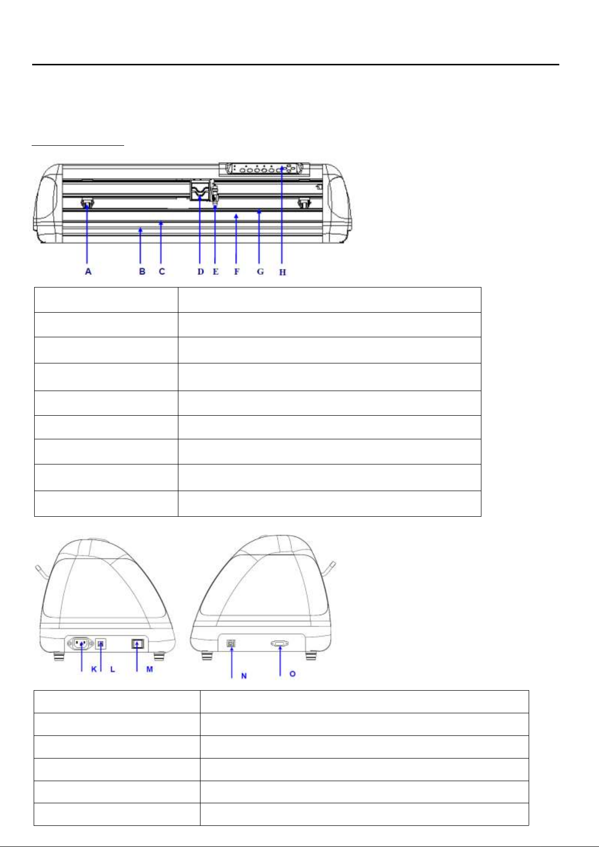
Object
Description
A Primary Pinch Roller
To help hold the media during cutting.
B Slicing Groove
To help slice off media.
C Alignment Ruler
To align media with clear guideline marks
D Carriage
To help perform cutting job with installed blade or pen.
E Blade Holder
To hold the blade.
F Platen
The surface for holding and supporting media in operation.
G Cutting Strip
To protect blade and plate in operation.
H Control Panel
To consist of 10 control keys and 6 LED lights.
Object
Description
K AC Power Connector
To insert the AC power cord.
L Fuse
3Amp.
M Power Switch
To turn on or off the machine.
N USB Connector
To connect the machine and a computer through a USB cable.
O Serial Interface Connector
To connect the machine and a computer through a RS-232 cable.
®
Xpres Cut Lite Overview
Thankyou for purchasing the Lite system.
Xpres Cut
®
Cutter Overview
1
Installation
To begin, unbox and place your cutter on a stable surface. Plug in the supplied power
cable and turn the cutter on (power button on the left hand side).
Important: Before beginning the following installation guide make sure that the USB Cable is NOT
connected to the PC. You will be prompted to install the USB cable later.
Driver Installation
Xpres Cut
The Lite system has two modes for installation:
®
- 32bit
- 64bit
We need to make sure the cutter is in the correct mode for the PC you are intending to install on.
Please note: You can find out whether your PC is 32 or 64bit by following the steps below:
- Click Start
- Right click on ‘my computer’ or ‘computer’ and select ‘properties’
- The required information will be within the specification shown in the properties window you have
opened
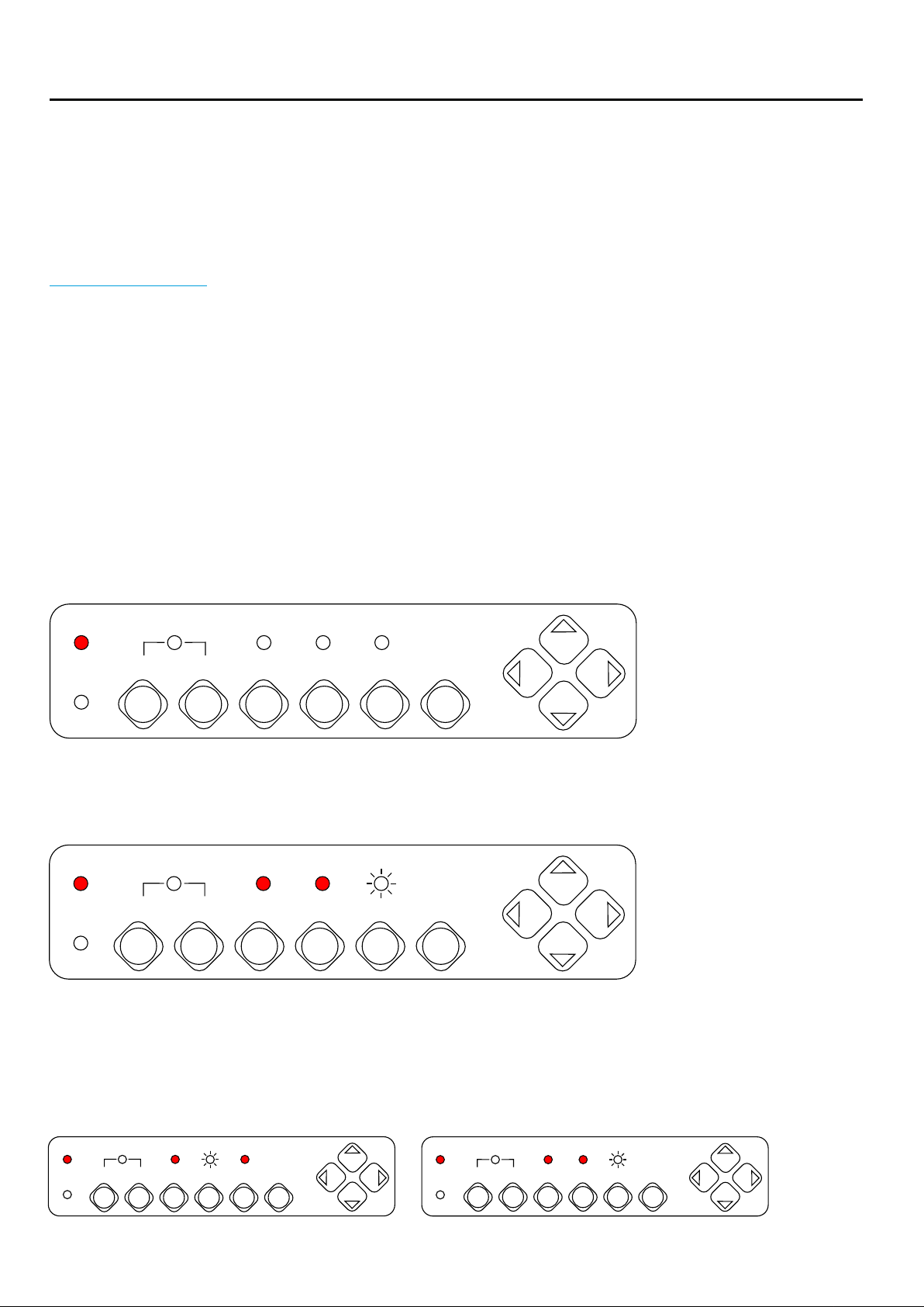
To check the cutter is running in the correct mode after being turned on, press the ‘On / Off Line’
button. You should now see lights shown as per the below (Power light on only):
Power
Error
On/Off Line
Pause
Repeat
Data Clear
Cut Test
Origin Set
Now press the ‘Pause’ and ‘Origin Set’ button together, you should see the ’Power’, ‘Repeat’
& ‘Data Clear’ ON, and the ‘Cut Test’ icon Flashing (You may see the ‘Data Clear’ Icon Flashing
instead of ‘Cut Test’):
Power
Error
On/Off Line
Pause
Repeat
Data Clear
Cut Test
Origin Set
To install the cutter on a 32bit system you need to press ‘Data Clear’, the ‘Data Clear’ button will
Flash.
To install the cutter on to a 64 bit system you need to press ‘Cut Test’, the ‘Cut Test’ button will now
Flash.
32bit
Power
Error
On/Off Line
Pause
Repeat
Data Clear
Cut Test
Origin Set
64bit
Power
Error
On/Off Line
Pause
Repeat
Data Clear
Cut Test
Origin Set
Once the correct mode is set, press the ‘Origin Set’ Button to confirm the setting (the ‘Repeat’, ‘Data
Clear’ and ‘Cut Test’ lights will go out).
2
Installation
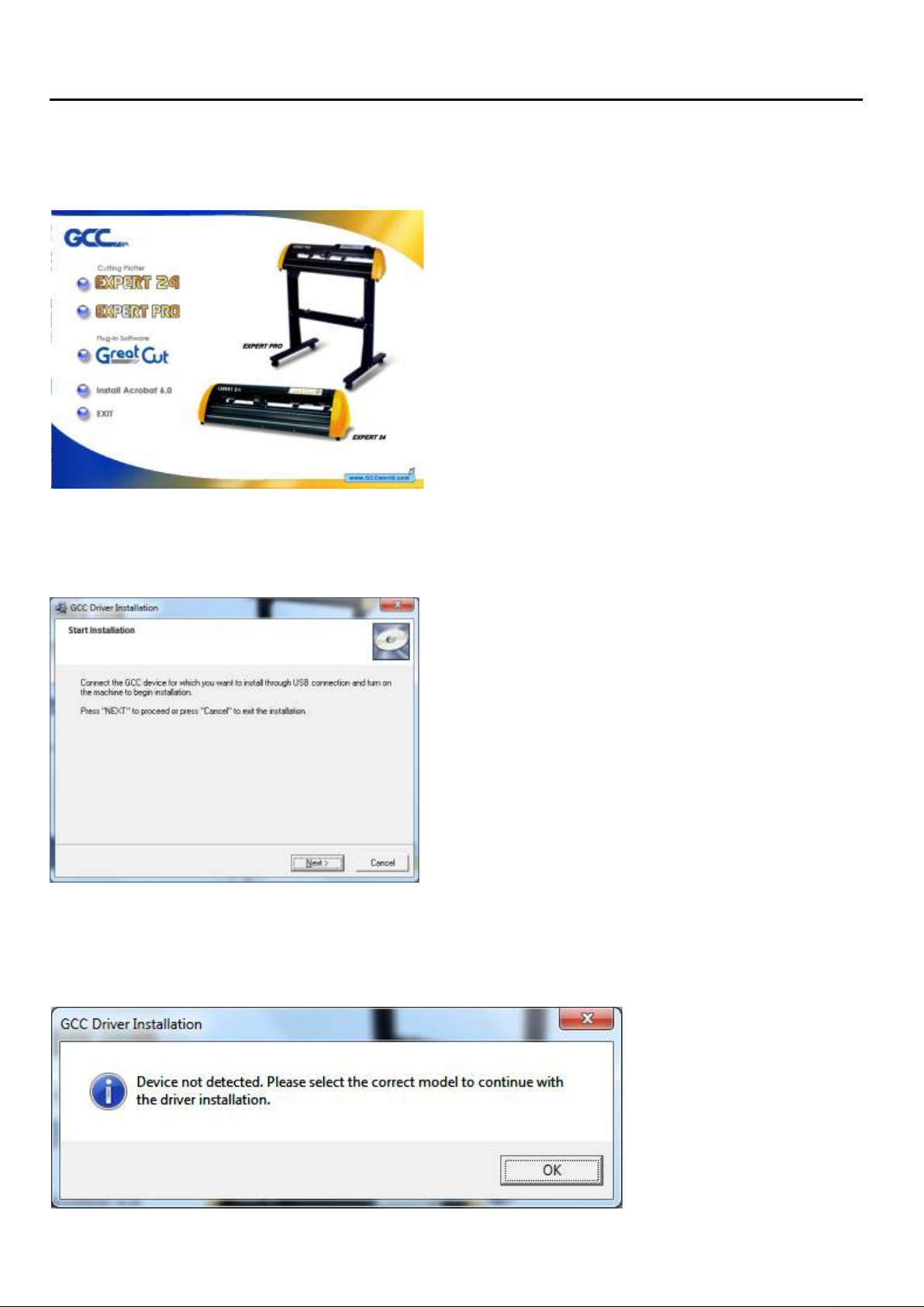
1. Insert supplied installation CD which will autorun and show the following screen. Select the
‘Expert 24' Option and choose the relevant 32bit or 64bit Windows Driver from the menu.
2. You will be prompted with the following screen, Connect the USB device and click ‘Next’.
Note: If installing on a Windows 64bit system please skip to step 6.
3. You will be prompted with the following screen, click ‘OK’ to continue.
3
Installation
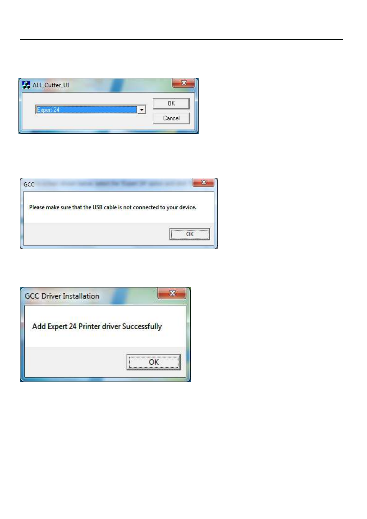
You will now see the screen shown below, select the ‘Expert 24' option and click ‘OK’.
You will be prompted with the screen shown below, you do NOT have to disconnect the USB if
prompted however this does not effect the install. Now click ‘OK’.
You will be now see confirmation that the driver has installed correctly. Click ‘OK’
4

Installation
VLCD
What is VLCD? VLCD is a small piece of software that allows you to connect the Lite
system with your PC. the VLCD Software is your control panel to control certain parts of the cutter,
such as Force, Media weight, Offset etc.
Xpres Cut
The Lite system will not operate without the use of the VLCD.
To use the VLCD we click on the accessories option from the installation CD menu (Under ‘Expert 24').
®
Xpres Cut
®
This will open up a new folder as shown below:
Place the VLCD2.EXE file on your desktop.
5

Installation
Connecting t sytem with VLCDhe LiteXpres Cut
Double click the VLCD2.EXE on your desktop, you should see the window below:
®
Click on the drop down list, select the USB or Expert 24 option and then click ‘Connect’. You should
now see the window below, the Model and Version should be visible and the options are now active:
Select the relevant force required for the material you intend to cut and click ‘Update Setting’ (a guide
for forces can be found on our website at www.xpres.co.uk).
Now close the VLCD to complete the setup. The VLCD software must be closed for the cutter operate.
6

CorelDRAW Overview
Introducing CorelDRAW and its tools
7

CorelDRAW Overview
Common CorelDRAW Tasks
8

Operation
Below shows the layout of the control panel and the relevant functions:
Power
Error
POWER LED To indicate the power status ( light up: power on; light off: power off )
ERROR LED To indicate the error status ( light up: error; light off: normal )
ON/OFF LINE To switch modes or stop cutting job( light up: on-line; light off: off-line )
PAUSE To temporarily halt cutting process or to continue
REPEAT To repeat last job.
DATA CLEAR To clear up buffer memory.
On/Off Line
Key Function
Pause
Repeat
While in on-line mode: only ON/OFF LINE and PAUSE keys activated
While in off-line mode: the settings in VLCD can be adjusted.
Data Clear
Cut Test
Origin Set
CUT TEST To perform cutting tests in different ways.
ORIGIN SET To reset origin at a new position.
*Make sure the machine is in off-line mode to enable this function.
4 Arrow Keys To move carriage position, select function, or change setting.
Blade Installation
Install the blade as shown in diagrams below.
Open the Blade Holder Clamp and insert the blade ensuring that the outer ring of the blade will slot
in to the groove of the clamp arm (as shown above).
9

Operation
Loading the media
. 1. Lift the 2 levers at the back of cutter to raise pinch rollers
2. Load your media on the platen and slide it under the pinch rollers from either the front side or the
backside.
3. Move the pinch rollers manually to the correct position. Be sure the pinch rollers are positioned
below the white marks as shown below. Always move the pinch rollers by hand from the back of
the cutter. Once in position use the clamps to lock the pinch rollers in to position.
Correct
Note: Be careful to position the pinch rollers so that they are not too close to the edges of the vinyl
and do not extend beyond the edges of the vinyl. If the pinch rollers are too close to the edge of the
vinyl this could cause the vinyl to come free from the pinch rollers if not positioned correctly i.e. if the
vinyl is not straight.
Incorrect
10

Operation
If using a roll of vinyl, you can position the roll on the Support Bracket shown below to allow the vinyl
to unroll freely.
Creating transfers
Now the vinyl is loaded in to the cutter correctly you can begin to create your transfer ready for
cutting.
1. Open CorelDRAW and select a new page. Now click on the Text Tool ( ). With the Text Tool
Selected click once on screen - you will notice the cursor flashing on screen awaiting input. Enter
your text and select the relevant font. In this example we create the word ‘XPRES’ and use an Arial
Black font.
XPRES
2. Select the Pick Tool ( ), you can now adjust the size of the text by dragging the nodes (which
show when an item is selected).
Left click the node and drag to adjust the size
You can also adjust the size accurately by typing in the required size in to the Object Size area on
the property bar.
Note: You adjust the height and width measurement independent of each by unlocking the
‘non-propertional scaling/sizing ratio’ padlock ( ).
11
Operation
3. Draw a weed box around the text using the Rectangle Tool ( ) as shown below. This gives us a
start point for weeding once the transfer has been cut. (With the Rectangle Tool selected, Left click
and drag the cursor around the desired objects).
XPRES
4. With the Pick Tool ( ), left click in a blank area of the page and drag the cursor over the text and
the weed box whilst holding left click, this will allow you to select both the text and the weed box as
one object. You can now group these objects together (Arrange > Group or ). See ‘Grouping and
Ungrouping’ on page 8 for more information.
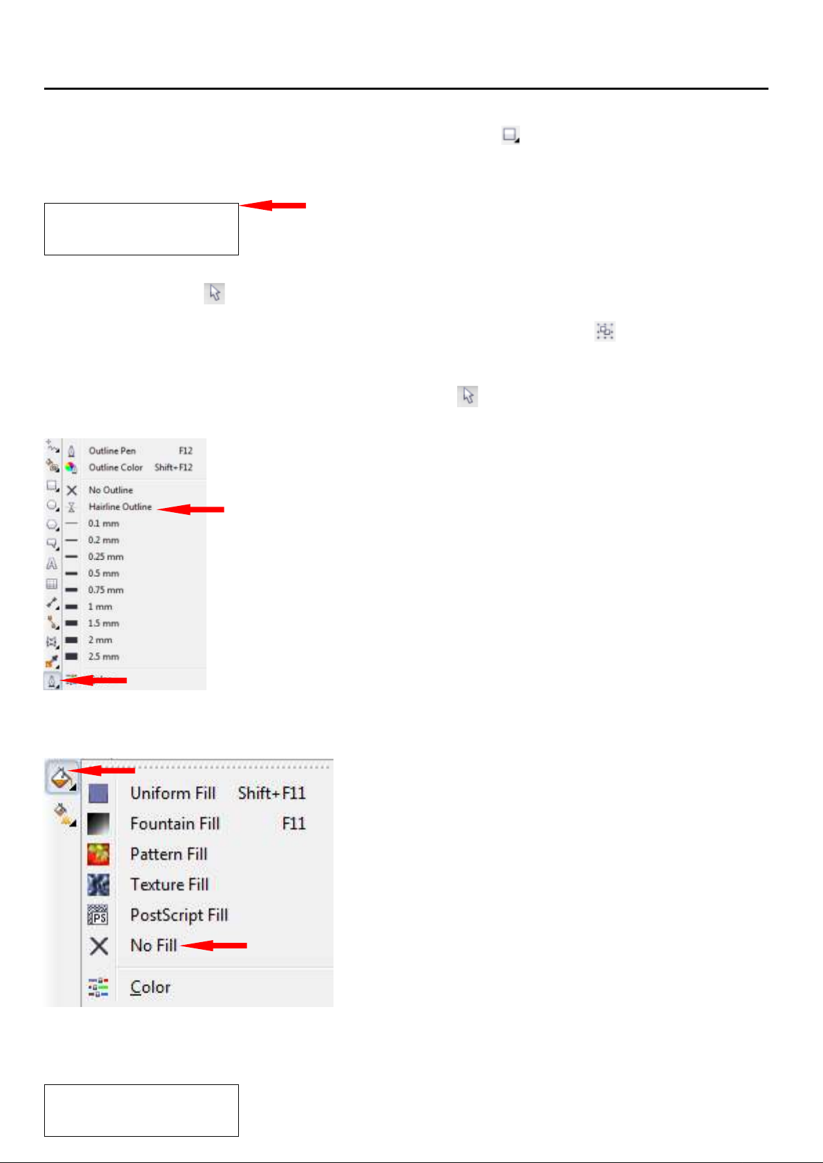
5. Making sure the image is selected with the Pick Tool ( ), as explained in step 4, click on the
‘Outline Tool’ and select ‘Hairline Outline’.
Weed Box
6. Now click on the ‘Fill Tool’ and select ‘No Fill’.
Your text should now look like the following, with no fill to the design and the outline set to a hairline
outline:
Note: The cutter will only recognise Hairline Outlines. Every design
XPRES
must be set to a Hairline Outline to allow the cutter to operate.
12

Operation
7. Now mirror the image by clicking on the horizontal mirror button on the property bar ( ). Your text
will now be mirrored on screen.
XPRES
8. Before sending the image to print you need to make sure that the image you intend to cut will fit on
the vinyl within the cutter. To do this you will need to open the VLCD software which was earlier
placed on the desk top.
Make sure the cutter is turned ON and open the VLCD2 software. Select the relevant option from the
dropdown list and click Connect on the VLCD2 display. The Width will now be displayed as shown:
This width measurement is the measurement of cuttable vinyl. Note: the cutter will measure the vinyl
between the two outer pinch rollers.
Now that you know the width of the vinyl we can use this measurement within the CorelDRAW
document. With no objects highlighted in CorelDRAW (deselect any objects by clicking on a blank
area of the document) the property bar shows the current page sizes.
You can change the width of the page to match the width of the vinyl in the cutter (width displayed in
the VLCD2 software as above).
(1000mm is recommended to represent 1meter of vinyl).
Note: Enter the width in CorelDRAW approximately 10mm smaller than the actual width of the
material. For example the width above shows 431.7mm. In the width of the page size in CorelDRAW
enter 420mm. This allows a small amount of room for error when setting up your transfers on your
media.
TIp: Make the length of the page MORE than the width.
13

Operation
You now know that the width of the page layout in CorelDRAW matches the vinyl loaded in to the
cutter. This allows you to maximise the use of the vinyl. For example producing several duplicated
designs (see ‘Duplicating Objects’ on page 8) we can arrange our designs within the page area as
demonstrated below:
The example below shows the duplicated designs hanging over the edge of the page size in
CorelDRAW, if this design was sent to cut, the job could not be completed as the vinyl is not wide
enough to produce the transfers positioned in this way.
14

Operation
Now the design is positioned correctly, you need to rotate the design so that the bottom edge of the
design faces towards the left hand side of CorelDRAW.
Rotate 90 or 270 (depending on how the design is layed out) by highlighting all objects and
entering ‘90/’270'' in the ‘Angle of Rotation’ ( ) tool on the property bar. Your design should be
rotated as the below shows.
.
° °
Note: This step allows us to position the cut
correctly in the print preview page in the following
steps
9. Click File > Print or select the Print Icon from the Property Bar ( ). From the Print Window select
the ‘Expert 24'
Important: If shown the message below, select ‘No’. This message occurs if the paper length in
CorelDRAW is not set longer than the width as explained in step 8.
Click ‘Print Preview’
15

Operation
You will see the layout below (the print preview page will always show a pre determined page layout
regardless of the page size set in CorelDRAW beforehand).
Click ‘Bottom Left Corner’ from the drop down list within the Print Preview screen to position the
design along the left hand edge of the print preview ready to print.
The area above highlighted in red shows the leading edge of the roll of vinyl placed in the cutter.
Placing the design in the ‘bottom left hand corner’ on screen positions the design to the front of the
vinyl in the cutter to maximise the vinyl usage when cutting.
16

Operation
Note: Always check the force using the ‘Test Cut’ button before beginning to cut your transfer. To do
this press the ‘On/Off Line’ button to turn the cutter Offline (On/Off Line LED will be off).
Whilst the cutter is Offline press the ‘Cut Test’ button once. The cutter will now cut the pattern below:
If you weed away the square, you should be left with a lightly visible crosshair scoring in the backing
of the vinyl. This shows you have the correct force.
If you are unable to weed away the square you need to increase the force and repeat the Cut Test.
To increase the force open up the VLCD2 program (you may need to connect the cutter once more as
shown on page 6 and adjust the force in increments of 10g. Now click ‘Update’ to confirm the
change.
)
Tip: Start on a low force and work
your way up. This is to prevent
accidentally cutting through the vinyl
and damaging the blade and
cutting strip.
Now Click File > Print or the Print Icon ( ). Your design will begin to cut.
Once cut weed your design leaving your transfers ready to be pressed as shown below..
17

Troubleshooting
Warning Indicators
Error
On/Off Line
Repeat
Data Clear
Cut Test
1
Cutting area error
2
Command error
3
Lever up or no media
4
Cannot Repeat
5
Communication error
6
Width sensor error
7
Check media drum or X motor
What if Expert 24 cannot operate?
If your cutter does not respond, please check the following items first:
Is the power cord plugged in properly?
Is the power cord connected to the power connector properly?
Is the power switch turned on?
If the above has been checked: If the POWER LED lights on, the cutting should be in a normal
condition ready to cut. In this case double check that the information being sent from the PC is set to
a ‘Hairline’ Outline.
The cutter is not cutting through the material correctly
Check the force setting, if that does not work try a new blade or cutting strip in case the old ones
have become damaged or worn.
Warning Indicators
When the ERROR LED flashes, take the necessary actions according to the following instructions. When
the problems are solved, the ERROR LED will turn off automatically. Pressing the ON/OFF LINE button
can also turn off the ERROR LED.
On = Off =
Warning 1 Cutting area error
This condition indicates that the cutting area s bigger than the vinyl width.
You can solve the problem by:
- Reloading a wider or longer media.
- Moving the pinch rollers to widen the cutting area.
- Re-scale the design to a smaller size.
Flashing =
18

Troubleshooting
Warning 2 Command error
If the cutting cannot recognise the commands from your computer, please check that the information
being sent to the cutter is set to a ‘hairline’ outline.
Warning 3 Lever up or no media
Check that you have lowered the lever down and make sure that you load the media before cutting.
Warning 4 Cannot repeat cutting
There are two possibilities:
- There is no data in the buffer: please resend the job from your computer.
- The buffer is full: please resend the same job from your computer.
Under both conditions, press the ON/OFF LINE key to clear the warning message.
Warning 5 Communication error
Check that the USB cable has been connected to the cutter and computer properly.
If so, then check whether the interface settings are correct; check the cutter is the correct mode i.e. 32
or 64bit. Then, press ON/OFF Line key to switch back to On Line mode.
Check that the VLCD software has been connected.
Warning 6 Width sensor error
Check that the pinch rollers are positioned above white markers and reload the media.
If you have any further questions please contact the Xpres Technical Department on
01332 858333 or visit WWW.XPRES.CO.UK
click on the Technical Support section, then the FAQ database
19
 Loading...