


XPiQ inc JPS250PS48C, JPS250PS24C, JPS250PS24, JPS250PS15C, JPS250PS15 Datasheet
...JPS250 Series Application Note
JPS250 Series
Application Note
Contents:
1.Introduction
2.Safety Agency Approvals
3.Emission Standards
4.Input Specifications
5.Output Specifications
6.General Specifications
7.Environmental Specifications
8.Mechanical Specifications
9.Control & Supervisory Signals
10.Characteristic Curves
11.Part Numbering (Options)
12.Warranty Statement
Section |
1: |
Introduction |
|
The |
JPS250 |
Series |
Switching Power Supply is a single output switcher |
that |
utilizes |
Zero |
Voltage / Zero Current topology to allow efficient |
operation, small size and quite operation. The Supplies offer 250 watt
operation with |
18 cfm airflow and 200 watt convection cooled operation. |
|||||
Features |
Include: |
|
|
|
||
§ |
Ideal |
for |
1U |
High |
/ Low Profile |
Applications |
§ |
Active Power |
Factor |
Correction for |
EN61000-3-2 Compliance |
||
§Greater than 80% Efficiencies
§World-Wide Safety Approvals
§Class B Emissions
§Full Featured Control and Status Signals
Section 2: Safety Agency Approvals
UL |
1950..................................................................................................... |
Approved |
CSA |
22.2 # 234.................................................................................... |
Approved |
TUV |
EN60950 ............................................................................................ |
Approved |
CE |
Mark............................................................................................................ |
Filed |
Section |
3: Emission |
Standards |
|
|
|
||
FCC.................................................................................................. |
|
|
|
|
20780 |
Level |
B |
CISPR ......................................................................................... |
|
|
|
|
EN55022 |
Class |
B |
EN61000-3-2 |
..................................................................................................... |
|
|
|
|
Pass |
|
EN61000-4-2 level 4 |
(ESD Susceptibility) .................................................. |
|
8 |
kv |
|||
EN61000-4-3 level 3 |
(Radiated |
Susceptibility) ..................................... |
|
10 V/M |
|||
EN61000-4-4 level 3 |
(EFT / |
Burst) ............................................................ |
|
±2kv |
|||
EN61000-4-5 |
class 3 |
(Input |
Transient Protection) ............. |
1 kV line to line |
|||
|
|
|
|
2 |
kV Line to |
Ground |
|
Headquarters: 508-429-9883 |
1 |
JPS250 Series Application Note
Section |
4: |
Input |
Specifications |
|
|
VAC |
Input |
Range................................................. |
Universal Input (85-264 VAC) |
||
Input |
Frequency.......................................................................................... |
|
47-63Hz |
||
Turn |
on/off |
VAC ........................................... |
on @ 82 VAC / off @ 80 VAC |
||
Inrush Current .............................. |
|
30a @ 115 VAC / 60a @ 230 VAC max |
|||
Nominal Input |
Current ..................... |
2.75a @ 115 VAC / 1.4a @ 230 VAC |
|||
VDC |
Input |
Range ...................................................................... |
170 – |
370 VDC |
|
Hold-up Time ............................................................................... |
|
20ms |
minimum |
||
Input |
Protection |
............................................................................. |
Single |
5A Fuse |
|
Power Factor .................................................................................... |
|
0.9 |
minimum |
||
Leakage Current .......................................................................................... |
|
<700uA |
|||
Section |
5: Output |
Specifications |
|
|
|
|
|
||||||
Output Power.......................................................................................... |
|
|
|
|
|
|
|
250 Watts |
|||||
Minimum |
Load Required ................................................................................... |
|
|
|
|
|
±0.5% |
|
n/a |
||||
Line |
Regulation ......................................................................... |
|
|
|
|
|
|
maximum |
|||||
Load |
Regulation ........................................................................... |
|
|
|
|
|
|
±1% |
maximum |
||||
Set-Point |
Tolerance......................................................................................... |
|
|
|
|
|
|
|
|
±1% |
|
||
Adjustment Range via trim |
pot.................................................................. |
|
|
|
|
|
|
±10% |
|
||||
Ripple & |
Noise................................................. |
|
|
|
|
1% pk-pk maximum |
(20 mHz) |
||||||
Transient |
Response ................................................................. |
|
|
|
|
|
|
4% max |
deviation, |
||||
|
|
|
|
|
|
<500µs recovery with 25% load change |
|||||||
Over |
Voltage |
Protection .............................. |
|
|
|
115-140% of nominal, recycle AC |
|||||||
Over |
Current |
Protection ......................... |
|
|
115-140% |
of nominal, auto |
recovery |
||||||
Over |
Temperature Protection |
.................................................................... |
|
|
|
|
|
|
standard |
||||
|
|
|
|
|
|
|
|
|
|
|
|
||
|
|
|
|
|
|
|
|
Output |
Currents: |
|
|
||
|
|
|
Maximum |
Output |
|
with |
Convection |
|
|||||
Model |
|
Power(1) |
Voltage |
|
18 CFM |
Cooled |
|
||||||
JPS250PS05 |
225 |
W |
5 |
V |
45.0 |
A |
36.0 |
A |
|
||||
JPS250PS12 |
250 |
W |
12 |
V |
21.0 |
A |
17.0 |
A |
|||||
JPS250PS15 |
250 |
W |
15 |
V |
17.0 |
A |
13.5 |
A |
|||||
JPS250PS24 |
250 |
W |
24 |
V |
10.4 |
A |
8.5 |
A |
|||||
JPS250PS48 |
250 |
W |
48 |
V |
5.2 |
A |
4.3 |
A |
|||||
|
|
|
Table 1: |
Output Voltages & |
Currents |
|
|
|
|||||
Section |
6: General |
Specifications |
|
|
|
|
||||
Efficiency ............................................. |
|
|
|
>80% Typical |
(see |
characteristic |
curves) |
|||
Power Density .................................................................................... |
|
|
|
|
|
|
4.9w |
per in3 |
||
MTBF ......................................................... |
|
|
|
>200,000 |
Hours |
per MILHDBK 217F |
||||
Withstand |
Voltage ..................................................... |
|
|
|
3000 VAC Input to Output |
|||||
|
|
|
|
|
1500 VAC Input to Ground |
|||||
|
|
|
|
|
500 VAC Output to Ground |
|||||
|
|
|
|
|
|
|
||||
Model |
|
Eff.% |
Voltage |
|
Current |
|||||
|
|
|
|
|
|
|
|
|||
JPS250PS05* |
81.5 |
- |
84.9 |
4.94-4.95 |
|
45 A* |
||||
JPS250PS12 |
82.6 |
- |
85.1 |
11.973- |
|
21 |
A |
|
||
|
|
|
|
|
11.976 |
|
|
|
|
|
JPS250PS15 |
83 |
- |
85.5 |
14.856- |
|
17 |
A |
|
||
|
|
|
|
|
14.862 |
|
|
|
|
|
JPS250PS24 |
83 |
- |
87 |
23.977- |
|
10.4 |
A |
|
||
|
|
|
|
|
23.977 |
|
|
|
|
|
JPS250PS48 |
83.6 |
- |
87.4 |
47.915- |
|
5.2 |
A |
|
||
|
|
|
|
|
47.904 |
|
|
|
|
|
|
* 225 |
Watts Maximum Power |
for 5v output |
model |
|
|
||||
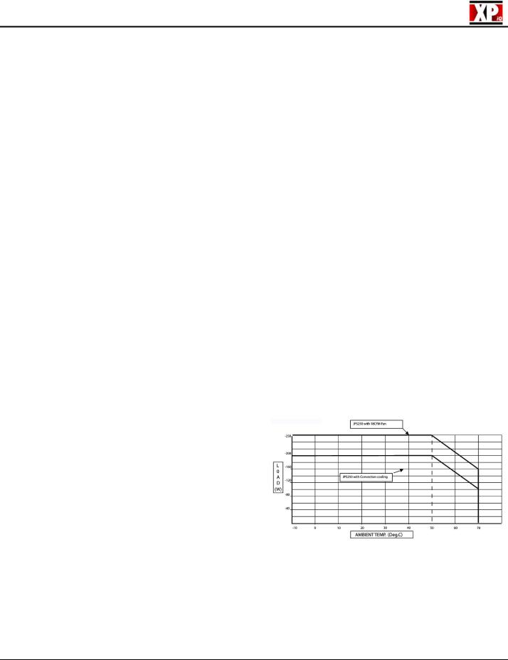
Section 5: Environmental |
Specifications |
|
Operating |
Temperature ................................................................................. |
0-50°C |
De-Rating |
........................................................... |
See De-Rating Curves (Table 3) |
Cooling ..................................................................... |
|
18cfm for 250 W operation |
.......................................................................... |
|
Convection for 200 W Operation |
Storage Temperature ......................................................................... |
-20 / +85°C |
|
Temperature ..................................................................Coefficient |
±0.05% / °C |
|
Humidity ......................................................................... |
(non - condensing) |
5-95% |
Altitude .................................... |
10,000 Feet |
Maximum for 250 Watt Operation |
* De-Rate 5v output model 10%
Headquarters: 508-429-9883 |
2 |

JPS250 Series Application Note
Section 6: |
Mechanical |
Specification |
|
|
|
|
Description ........................................................................... |
|
U-Frame |
Construction |
|||
Size ............................................... |
8 x 4.2 x 1.5” (203.2 x |
106.7 |
x 38.1mm) |
|||
Weight................................................................................................................ |
|
|
|
|
900g |
|
Mechanical |
Drawing for all |
models other than |
JPS250PS05 |
|||
|
|
|
|
|
|
|
3.75”
95.3mm
#6-32 Mounting Hole x 8  Max Penetration of 4mm
6.5” (165.1mm)
Mechanical Drawing for JPS250PS05 (requires more terminals for output current)
TB2 PIN Assignments: TB2 terminal block connections are for the output Voltage and current and are defined as follows:
TB3 PIN Assignments: TB3 connection is for 12v @ 300ma fan output (not available on the JPS250PS05). Pin 1 is +12v, Pin 2 is Return. Mating Connector is Molex 5045-02A or equivalent.
TB4 Pin Assignments: TB4 connections are for Control and Supervisory Signals. Mating Connector is 70246-10
Headquarters: 508-429-9883 |
3 |
 Loading...