


WDF750SAYW0
Whirlpool WDF750SAYW0, WDF750SAYM0, WDF750SAYB0, GU3600XTVY3, GU3600XTVY4 Installation Guide
...
®
iNSTALLATiON iNSTRUCTiONS
UNDERCOUNTER DISHWASHER
iNSTRUCTiONS D'INSTALLATION
LAVE-VAISSELLESOUS PLAN DE TRAVAIL
Table of Contents ................................... 2
Table des matieres .................................. 24
W10282549A
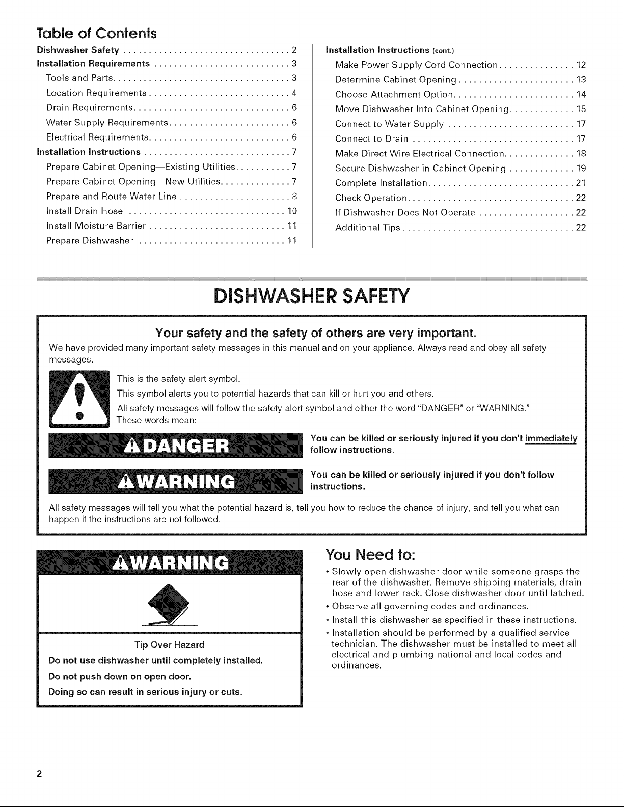
Table of Confenfs
Dishwasher Safety ................................. 2
installation Requirements ........................... 3
Tools and Parts ................................... 3
Location Requirements ............................ 4
Drain Requirements ............................... 6
Water Supply Requirements ........................ 6
Electrical Requirements ............................ 6
installation instructions ............................. 7
Prepare Cabinet Opening--Existing Utilities ........... 7
Prepare Cabinet Opening--New Utilities .............. 7
Prepare and Route Water Line ...................... 8
install Drain Hose ............................... 10
install Moisture Barrier ........................... 11
Prepare Dishwasher ............................. 11
DISHWASHER SAFETY
installation instructions (cent,}
Make Power Supply Cord Connection ............... 12
Determine Cabinet Opening ....................... 13
Choose Attachment Option ........................ 14
Move Dishwasher into Cabinet Opening ............. 15
Connect to Water Supply ......................... 17
Connect to Drain ................................ 17
Make Direct Wire Electrical Connection .............. 18
Secure Dishwasher in Cabinet Opening ............. 19
Complete installation ............................. 21
Check Operation ................................. 22
If Dishwasher Does Not Operate ................... 22
Additional Tips .................................. 22
Your safety and the safety of others are very important.
We have provided many important safety messages in this manual and on your appliance. Always read and obey all safety
messages.
This is the safety alert symbol.
This symbol alerts you to potential hazards that can kill or hurt you and others.
All safety messages will follow the safety alert symbol and either the word "DANGER" or "WARNING."
These words mean:
You can be killed or seriously injured if you don't immediately
follow instructions.
You can be killed or seriously injured if you don't follow
instructions.
All safety messages will tell you what the potential hazard is, tell you how to reduce the chance of injury, and tell you what can
happen if the instructions are not followed.
You Need to:
, Slowly open dishwasher door while someone grasps the
rear of the dishwasher. Remove shipping materials, drain
hose and lower rack. Close dishwasher door until latched.
, Observe all governing codes and ordinances.
, install this dishwasher as specified in these instructions.
, installation should be performed by a qualified service
Tip Over Hazard
Do not use dishwasher until completely installed.
Do not push down on open door.
Doing so can result in serious injury or cuts.
technician. The dishwasher must be installed to meet all
electrical and plumbing national and local codes and
ordinances.
2
INSTALLATION REQUIREMENTS
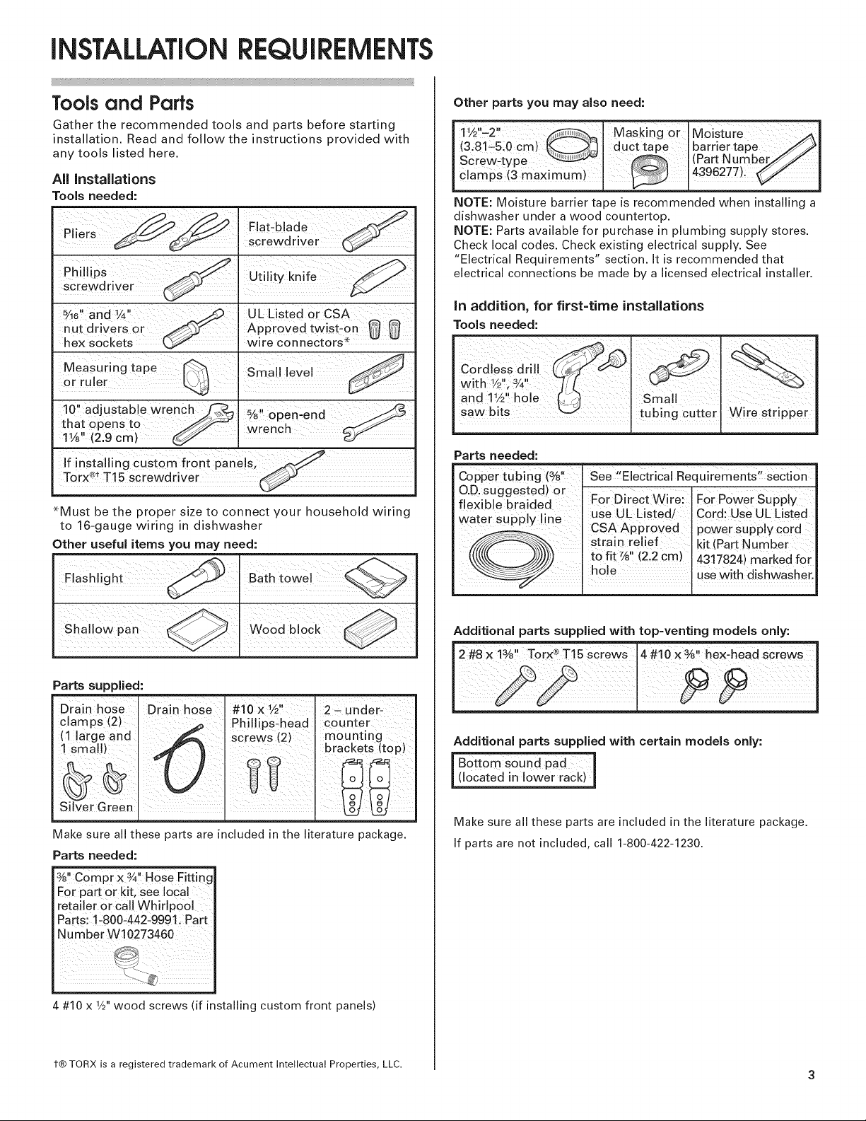
Tools and Parts
Gather the recommended tools and parts before starting
installation. Read and follow the instructions provided with
any tools listed here.
All Installations
Tools needed:
IF,at-b,ade
n,ers I screwdriver
5 1
_Ae and ¼ _..y'_ UL Listed or CSA
nut drivers or _ Approved twist-on ff
hex sockets _ wire connectors* v
10" adjustable wrench_ %" chert-end
that opens to _ wrench .-f-_-'_'-_'-
11/8"(2.9 cm) _.
If installing custom front panels, ..._y
Torx _t T15 screwdriver
-Must be the proper size to connect vour household wiring
to 16-gauge wiring in dishwasher
Other useful items you may need:
F ash ight _ Batht0we _
Other parts you may also need:
l 11/2'-2'' I Masking or IMoisture _i
(3.81-5:0 Cm) I du ct tape I barrier tape _1
Screw-type I I(Part Number T_J I
C ampsmaxim,m)/ 396277!:
NOTE: Moisture barrier tape is recommended when installing a
dishwasher under a wood countertop.
NOTE: Parts available for purchase in plumbing supply stores.
Check local codes. Check existing electrical supply. See
"Electrical Requirements" section. It is recommended that
electrical connections be made by a licensed electrical installer.
In addition, for first=time installations
Tools needed:
Cordless drill
• 1 " 3 "
with V2, Y4
and 11/2'' h
saw bits
Parts needed:
Co er tubin (%" 'see"Electrical Re uirements" section
PP g q
OD suggested) or
flex:blue braided For Direct Wire'.. For Power Supply
Water supp y ne use UL bsted/ ICord:Use UL L,sted
L_'..._......__j._..)_) tofit_ (2,2cm) 4317824)markedfor
CSA Appr0ved power Supply C0rd
str ain relief I idt (Part Number
h0!e uSe w!th dishWas her.
Parts supplied:
Drain hose
clamps (2)
(1 large and
1 small)
Silver Green, I
Make sure all these parts are included in the literature package.
Parts needed:
3A,ICompr x ¾11Hose Fit
Eor part or kit, see local
retailer or call WhirlpoOl
Parts: !-800:442-9991 iPart
NumberW10273460
4 #10 x 1/2"wood screws (if installing custom front panels)
Drain hose #10 x W'
screws (2)
d Phillips-head
I
2- under-
counter
mounting
brackets (top)
Additional parts supplied with top-venting models only:
Additional parts supplied with certain models only:
I B0tt0m Sound pad
I (located in lower rack) J
Make sure all these parts are included in the literature package.
If parts are not included, call 1-800-422-1230.
t® TORX is a registered trademark of Acument Intellectual Properties, LLC.
3

Location Requirements
Grounded electrical supply required.
Do not run drain lines, water lines or electrical wiring where
they can interfere with or contact dishwasher motor or legs.
The location where the dishwasher will be installed must
provide clearance between motor and flooring. Motor
should not touch the floor.
Do not install dishwasher over carpeted flooring.
Shelter dishwasher and water lines leading to dishwasher
against freezing. Damage from freezing is not covered by
the warranty.
A side panel kit is available from your dealer for installing
your dishwasher at the end of your cabinetry.
A moisture barrier accessory (Part Number 4396277) is
available from your dealer for installing underneath the
countertops. Call 1-800-422-1230 to order.
Check location where dishwasher will be installed. The
location must provide:
easy access to water, electricity and drain.
convenient access for loading and unloading dishes.
Corner locations require a 2" (5.1 cm) minimum
clearance between the side of the dishwasher door
and the wall or cabinet.
square opening for proper operation and appearance.
cabinet front perpendicular to floor.
level floor. (If floor at front of opening is not level with
floor at rear of opening, shims may be needed to level
dishwasher.)
Helpful Tip: Be sure to accurately measure dimensions
and ensure dishwasher is level if the floor in the
dishwasher opening is uneven (example: Flooring
extends only partway into opening).
NOTE: To avoid shifting during dishwasher operation,
shims must be securely attached to the floor.
If dishwasher will be left unused for a period of time or in a
location where it may be subject to freezing, have it
winterized by authorized service personnel.
Make sure pipes, wires and drain hose are within the
shaded area shown in the "Product and Cabinet
Opening Dimensions" section.
4
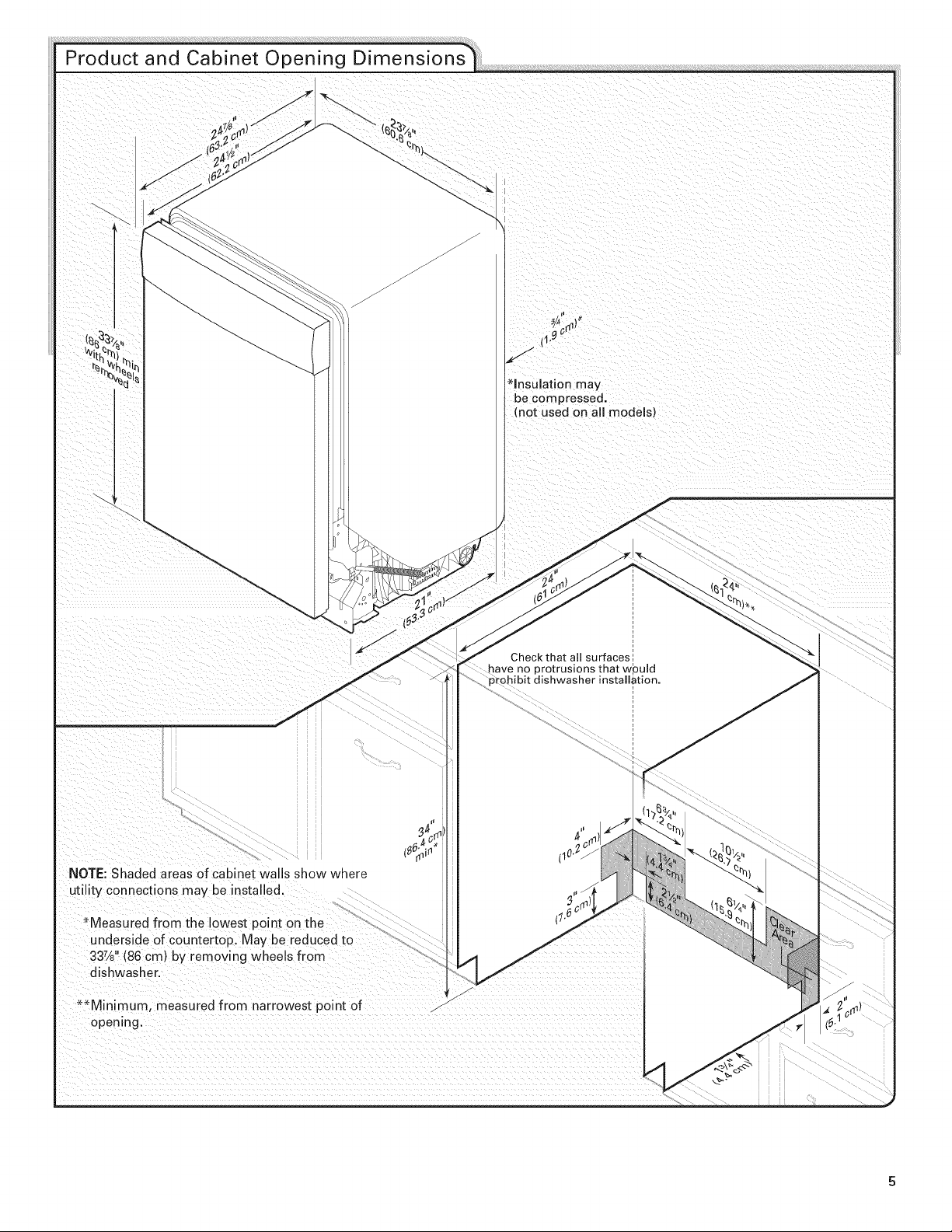
Product and Cabinet Opening Dimensions
*Insulation may
be compressed.
(not used on all models)
J
NOTE: Shaded areas of cabinet walls show where
utility connections may be installed.
*Measured from the lowest point on the
underside of countertop. May be reduced to
337/8"(86 cm) by removmg wheels from
dishwasher.
_*Minimum, measured from narrowest point of s
opening.
Check that all surfaces
have no protrusions that wpuld
_ohibit dishwasher installation.

Drain Requirements
Eiecfrical Requiremenfs
, A new drain hose is supplied with your dishwasher.
If this is not long enough, use a new drain hose with a
maximum length of 12' (3.7 m) (Part Number 3385556)
that meets all current AHAM/IAPMO test standards, is
resistant to heat and detergent, and fits the 1" (2.5 cm)
drain connector of the dishwasher.
Make sure to connect drain hose to waste tee or disposer
inlet above drain trap in house plumbing and 20"
(50.8 cm) minimum above the floor. It is recommended
that the drain hose either be looped up and securely
fastened to the underside of the counter, or be connected
to an air gap.
Be sure that the electrical connection and wire size are
adequate and in conformance with the National Electrical
Code, ANSI/NFPA 70 - latest edition and all local codes and
ordinances.
A copy of the above code standards can be obtained from:
National Fire Protection Association
One Batterymarch Park
Quincy, MA 02269
You must have:
120-volt, 60 Hz, AC-only, 15- or 20-amp, fused electrical
supply.
copper wire only.
We recommend:
a time-delay fuse or circuit breaker.
a separate circuit.
if connecting dishwasher
with a power supply cord:
, Use UL Listed power supply cord kit (Part Number
4317824) marked for use with dishwasher.
Power supply cord must plug into
a grounded 3 prong outlet, located in
the cabinet next to the dishwasher
opening. Outlet must meet all local
codes and ordinances.
Make sure to use an air gap if the drain hose is connected
to house plumbing lower than 20" (50.8 cm) above
subfloor or floor.
Use 1/2"minimum I.D. drain line fittings.
If required, the air gap, should be installed in accordance
with the air gap installation instructions. When you are
connecting the air gap a rubber hose (not provided) will
be needed to connect to the waste tee or disposer inlet.
Wafer Supply Requiremenfs
* A hot water line with 20-120 psi (138-862 kPa) water
pressure can be verified by a licensed plumber.
* 120°F (49°C) water at dishwasher.
* 3/8"O.D. copper tubing with compression fitting or
flexible braided water supply line (Part Number
4396897RP)
NOTE:1/2"minimum plastic tubing is not recommended.
* A 90 ° elbow with 3/4"Hose connection with rubber
washer
* Do not solder within 6" (15.2 cm) of the water inlet valve.
if connecting dishwasher with direct wiring:
* Use flexible, armored
or nonmetallic
sheathed, copper wire
with grounding wire
that meets the wiring requirements for your home and
local codes and ordinances.
* Use a UL Listed!CSA Approved strain relief.
iNSTALLATiON iNSTRUCTiONS
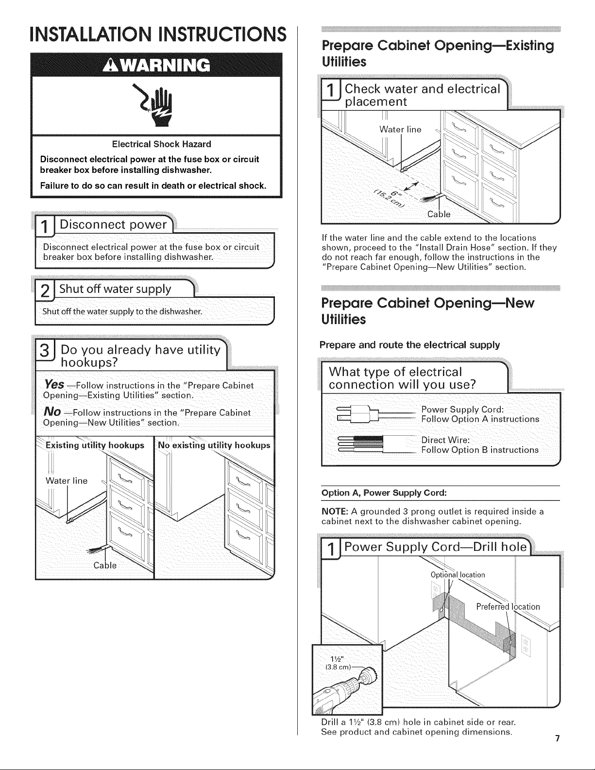
Electrical Shock Hazard
Disconnect electrical power at the fuse box or circuit
breaker box before installing dishwasher.
Failure to do so can result in death or electrical shock.
D,_c0n_eCt electr'C a' power at the fuSe b0X oi Circu,t i
breaker b0x bef°re !nsta!!!ng dishwash
Prepare Cabinet OpeningmExisfing
Utilities
If the water line and the cable extend to the locations
shown, proceed to the "Install Drain Hose" section. If they
do not reach far enough, follow the instructions in the
"Prepare Cabinet Opening--New Utilities" section.
Prepare Cabinet OpeningmNew
Utilities
Yes _F011ow instructions in the "Prepa[e cabinet
Opening_Existing utilities,, section:
NO _FolloW instrUCti0nS inthe ,,Prepare Cabinet ....
Open!ng_New Ut!!it!es'! section:
E :isting g L ity hookups
Water line
Prepare and route the electrical supply
What type of electrical
connection will you use? L
Direct Wire:
F011ow opti0n B inst[uctionS
Option A, Power Supply Cord:
NOTE: A grounded 3 prong outlet is required inside a
cabinet next to the dishwasher cabinet opening.
Drill a 11/2'' (3.8 cm) hole in cabinet side or rear.
See product and cabinet opening dimensions.
7
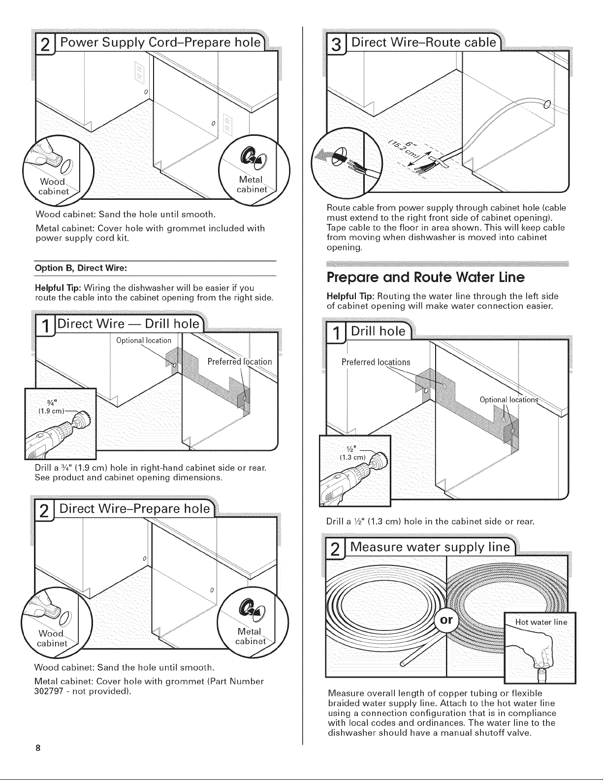
Woodcabinet:Sandtheholeuntilsmooth.
Metalcabinet:Coverholewithgrommetincludedwith
powersupplycordkit.
OptionB, Direct Wire:
Helpful Tip: Wiring the dishwasher will be easier if you
route the cable into the cabinet opening from the right side.
Drill a ¾" (1.9 cm) hole in right-hand cabinet side or rear.
See product and cabinet opening dimensions.
Route cable from power supply through cabinet hole (cable
must extend to the right front side of cabinet opening).
Tape cable to the floor in area shown. This will keep cable
from moving when dishwasher is moved into cabinet
opening.
Prepare and Route Wafer Line
Helpful Tip: Routing the water line through the left side
of cabinet opening will make water connection easier.
Drill hole
Preferred locations
Wood cabinet: Sand the hole until smooth.
Metal cabinet: Cover hole with grommet (Part Number
302797 - not provided).
8
Drill a V2" (1.3 cm) hole in the cabinet side or rear.
Measure overall length of copper tubing or flexible
braided water supply line. Attach to the hot water line
using a connection configuration that is in compliance
with local codes and ordinances. The water line to the
dishwasher should have a manual shutoff valve.
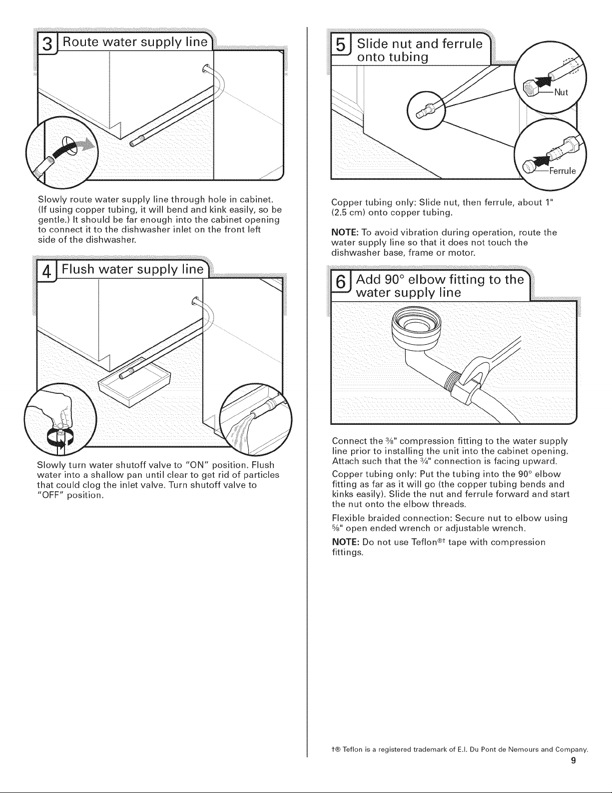
Slowlyroutewatersupplylinethroughholeincabinet.
(Ifusingcoppertubing,itwillbendandkinkeasily,sobe
gentle.)Itshouldbefarenoughintothecabinetopening
toconnectittothedishwasherinletonthefrontleft
sideofthedishwasher.
Slowlyturnwatershutoffvalveto "ON"position.Flush
waterintoashallowpanuntilcleartogetridofparticles
thatcouldclogtheinletvalve.Turnshutoffvalveto
"OFF"position.
Coppertubingonly:Slidenut,thenferrule,about1"
(2.5cm)ontocoppertubing.
NOTE:Toavoidvibrationduringoperation,routethe
watersupplylinesothatitdoesnottouchthe
dishwasherbase,frameormotor.
Connectthe3/8"compressionfittingtothewatersupply
linepriortoinstallingtheunitintothecabinetopening.
Attachsuchthatthe3/4"connectionisfacingupward.
Coppertubingonly:Putthetubingintothe90° elbow
fittingasfarasitwillgo(thecoppertubingbendsand
kinkseasily).Slidethenutandferruleforwardandstart
thenutontotheelbowthreads.
Flexiblebraidedconnection:Securenuttoelbowusing
%"openendedwrenchoradjustablewrench.
NOTE:DonotuseTeflon®ttapewithcompression
fittings.
t® Teflon is a registered trademark of EJ. Du Pont de Nemours and Company.
9
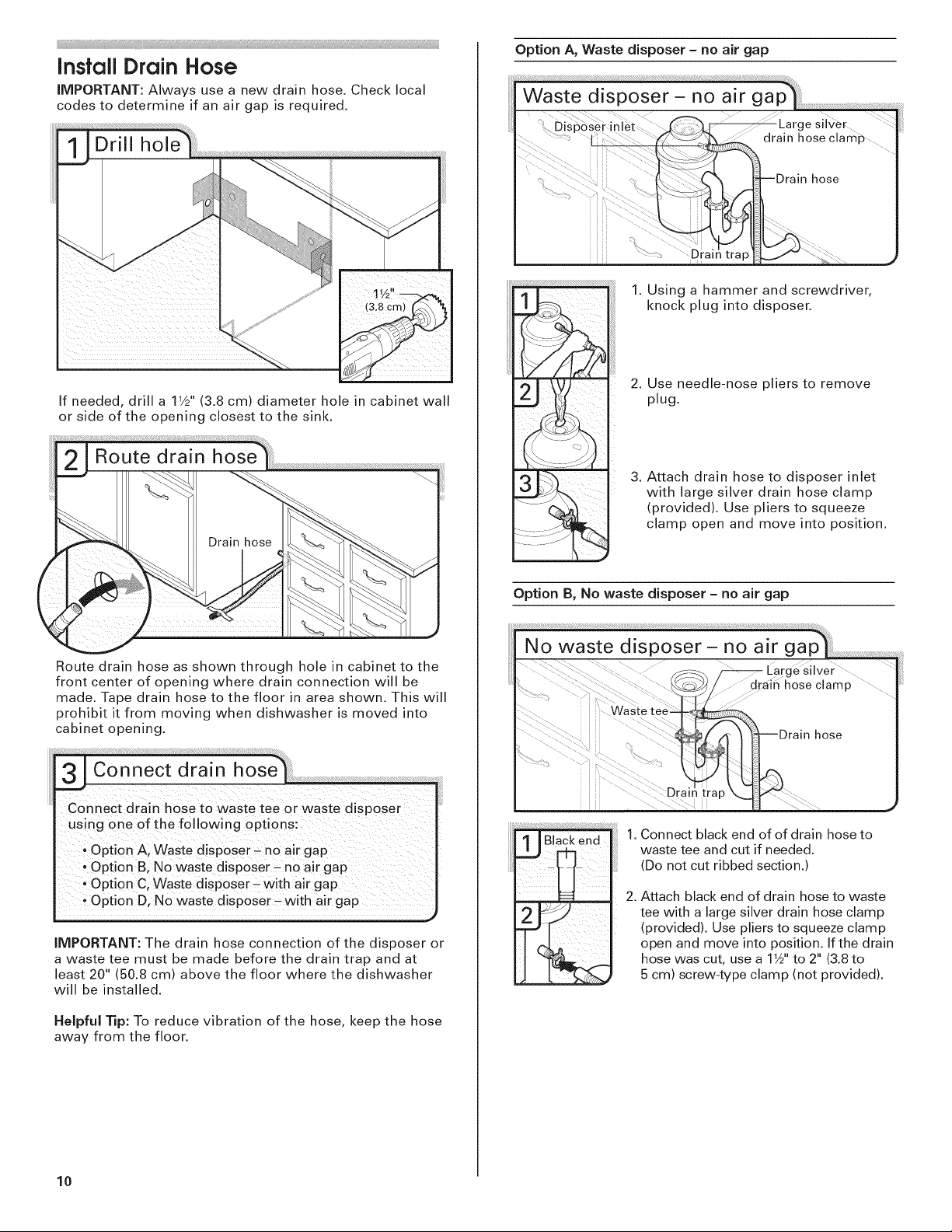
InsfallDrain Hose
IMPORTANT: Always use a new drain hose. Check local
codes to determine if an air gap is required.
If needed, drill a 11/2"(3.8 cm) diameter hole in cabinet wall
or side of the opening closest to the sink.
Option A, Waste disposer - no air gap
1. Using a hammer and screwdriver,
knock plug into disposer.
2. Use needle-nose pliers to remove
plug.
3. Attach drain hose to disposer inlet
with large silver drain hose clamp
(provided). Use pliers to squeeze
clamp open and move into position.
Route drain hose as shown through hole in cabinet to the
front center of opening where drain connection will be
made. Tape drain hose to the floor in area shown. This will
prohibit it from moving when dishwasher is moved into
cabinet opening.
31Connect drain hose
Con nect d raJn hoSe tO waste tee or Waste disposer
using one of the following options:
option A, Waste disposer _ n0 air gap
, opti0n B,NO Waste dispOser _no air gap
option C, Waste disposer Jwith air gap
OPtion D, No waste disposer _with air gap
IMPORTANT: The drain hose connection of the disposer or
a waste tee must be made before the drain trap and at
least 20" (50.8 cm) above the floor where the dishwasher
will be installed.
Helpful Tip: To reduce vibration of the hose, keep the hose
away from the floor.
Option B, No waste disposer - no air gap
1. Connect black end of of drain hose to
waste tee and cut if needed.
(Do not cut ribbed section.)
2. Attach black end of drain hose to waste
tee with a large silver drain hose clamp
(provided). Use pliers to squeeze clamp
open and move into position. If the drain
hose was cut, use a 1W' to 2" (3.8 to
5 cm) screw-type clamp (not provided).
10
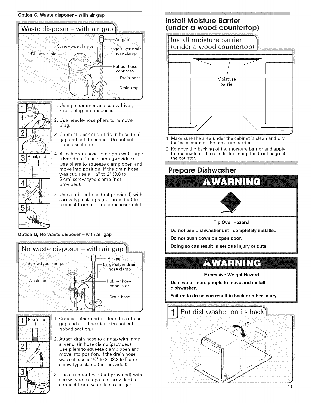
Option C, Waste disposer - with air gap
1. Using a hammer and screwdriver,
knock plug into disposer.
2. Use needle-nose pliers to remove
plug.
3. Connect black end of drain hose to air
gap and cut if needed. (Do not cut
ribbed section.)
4.
Attach drain hose to air gap with large
silver drain hose clamp (provided).
Use pliers to squeeze clamp open and
move into position. If the drain hose
was cut, use a 11/2'' to 2" (3.8 to
5 cm) screw-type clamp (not
provided).
Drain trap
Install Moisfure Barrier
(under a wood counterfop)
Moisture
barrier
1. Make sure the area under the cabinet is clean and dry
for installation of the moisture barrier.
2. Remove the backing of the moisture barrier and apply
to underside of the countertop along the front edge of
the counter.
Prepare Dishwasher
5. Use a rubber hose (not provided) with
screw-type clamps (not provided) to
connect from air gap to disposer inlet.
Option D, No waste disposer - with air gap
Connect black end of drain hose to air
gap and cut if needed. (Do not cut
ribbed section.)
2.
Attach drain hose to air gap with large
silver drain hose clamp (provided).
Use pliers to squeeze clamp open and
move into position. If the drain hose
was cut, use a 11A'' to 2" (3.8 to 5 cm)
screw-type clamp (not provided).
Tip Over Hazard
Do not use dishwasher until completely installed.
Do not push down on open door.
Doing so can result in serious injury or cuts.
Excessive Weight Hazard
Use two or more people to move and install
dishwasher.
Failure to do so can result in back or other injury.
Put dishwasher on its __
3.
Use a rubber hose (not provided) with
screw-type clamps (not provided) to
connect from waste tee to air gap,
11

Helpful Tip: Place cardboard under dishwasher until installed
in cabinet opening to avoid damaging floor covering. Do not
use door panel as a work table without first covering with a
towel to avoid scratching the door panel.
Using two or more people, grasp sides of dishwasher door
frame and place dishwasher on its back.
Using a 1/4"hex head socket, nut driver or Phillips
screwdriver, remove two screws attaching access panel
and lower panel to dishwasher. Do not remove tech
sheet from access panel.
NOTE: If using Option B, proceed to "Determine Cabinet
Opening," to continue with the installation of your
dishwasher.
Make Power Supply Cord Connecfion
Option A, Power Supply Cord:
Using a 1/4"hex head socket, nut driver or Phillips
screwdriver, remove terminal box cover. Retain for
later use.
Install a UL Listed/CSA Approved strain relief. Make sure
screwheads are facing to the left when tightening conduit
nut. Strain relief is provided with the power supply cord kit.
12
Route cord so that it does not touch dishwasher motor to
lower part of dishwasher tub. Pull cord through strain
relief in terminal bow. Take notice when installing or
removing the dishwasher in order to reduce the chance of
damaging the power supply cord.
Select UL Listed/CSA Approved twist-on wire connectors
(included with power supply cord kit) rated to connect your
power supply cord to 16-gauge dishwasher wiring.
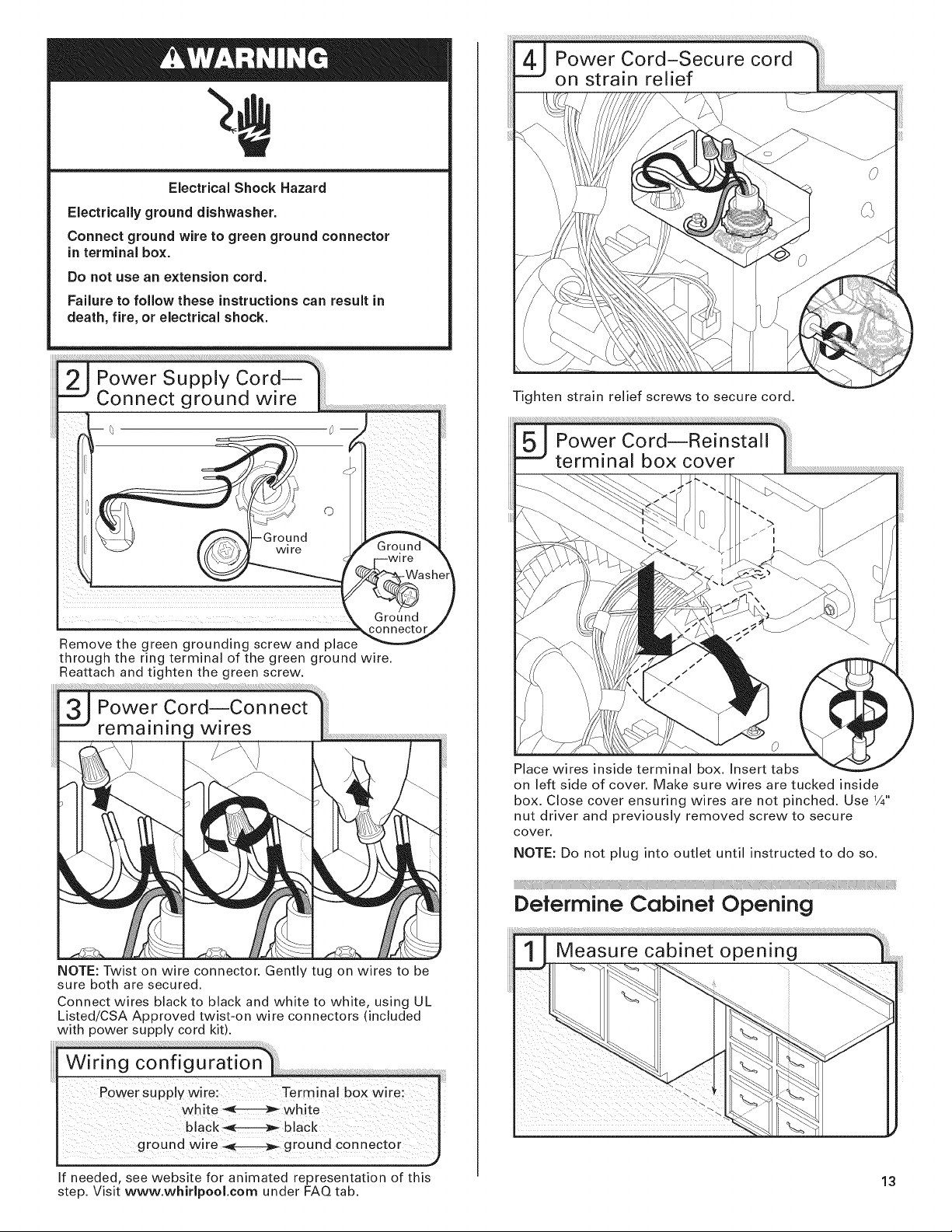
ElectricalShock Hazard
Electrically ground dishwasher.
Connect ground wire to green ground connector
in terminal box.
Do not use an extension cord.
Failure to follow these instructions can result in
death, fire, or electrical shock.
--" Connect ground wire |
--_.
Remove the green grounding screw and place
through the ring terminal of the green ground wire.
Reattach and tighten the green screw.
Tighten strain relief screws to secure cord.
Place wires inside terminal box. Insert tabs
on left side of cover. Make sure wires are tucked inside
box. Close cover ensuring wires are not pinched. Use 1/4"
nut driver and previously removed screw to secure
cover.
NOTE: Do not plug into outlet until instructed to do so.
Determine Cabinet Opening
NOTE: Twist on wire connector. Gently tug on wires to be
sure both are secured.
Connect wires black to black and white to white, using UL
Listed!CSA Approved twist-on wire connectors (included
with power supply cord kit).
If needed, see website for animated representation of this 13
step. Visit www.whirlpool.com under FAQ tab.
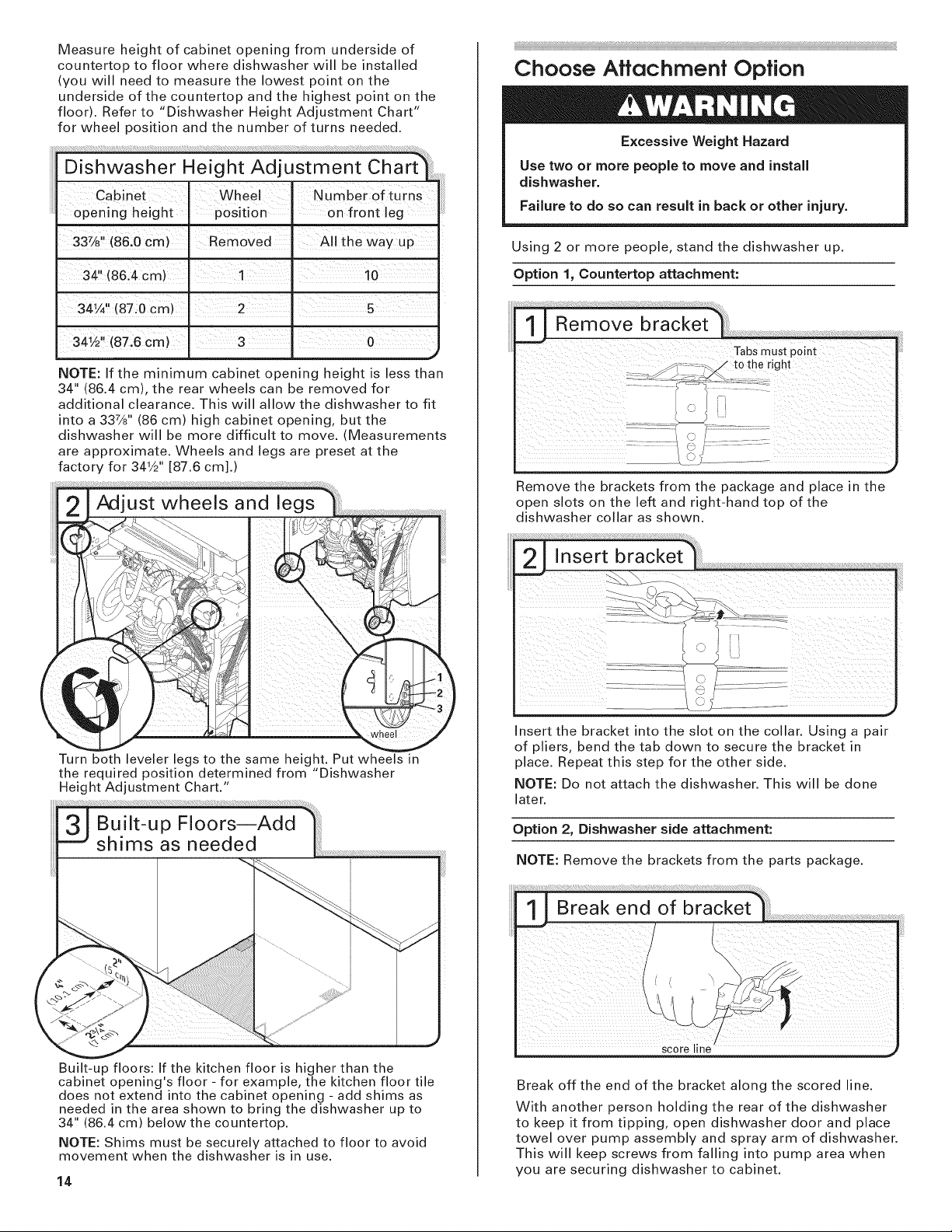
Measureheightofcabinetopeningfromundersideof
countertoptofloorwheredishwasherwillbeinstalled
(youwillneedtomeasurethelowestpointonthe
undersideofthecountertopandthehighestpointonthe
floor).Referto"DishwasherHeightAdjustmentChart"
forwheelpositionandthenumberofturnsneeded.
Cabinet I :Wheel Number°fturns
opening height position on front leg
Choose Attachment Option
Excessive Weight Hazard
Use two or more people to move and install
dishwasher.
Failure to do so can result in back or other injury.
33%" (86,0 cm) I Removed A!I the way up
" I
34 (86.4cm) . 1 10
341 ,,(87:0era)2 s
NOTE: If the minimum cabinet opening height is less than
34" (86.4 cm), the rear wheels can be removed for
additional clearance. This will allow the dishwasher to fit
into a 337/8`' (86 cm) high cabinet opening, but the
dishwasher will be more difficult to move. (Measurements
are approximate. Wheels and legs are preset at the
factory for 341/2'' [87.6 cm].)
Adjust wheels and legs
Using 2 or more people, stand the dishwasher up.
Option 1, Countertop attachment:
,,_
Remove the brackets from the package and place in the
open slots on the left and right-hand top of the
dishwasher collar as shown.
Turn both leveler legs to the same height. Put wheels in
the required position determined from "Dishwasher
Height Adjustment Chart."
Built-up floors: If the kitchen floor is higher than the
cabinet opening's floor - for example, the kitchen floor tile
does not extend into the cabinet opening - add shims as
needed in the area shown to bring the dishwasher up to
34" (86.4 cm) below the countertop.
NOTE: Shims must be securely attached to floor to avoid
movement when the dishwasher is in use.
14
)
J
nsert the bracket into the slot on the collar. Using a pair
of pliers, bend the tab down to secure the bracket in
place. Repeat this step for the other side.
NOTE: Do not attach the dishwasher. This will be done
later.
Option 2, Dishwasher side attachment:
NOTE: Remove the brackets from the parts package.
_cole i ne /
Break off the end of the bracket along the scored line.
With another person holding the rear of the dishwasher
to keep it from tipping, open dishwasher door and place
towel over pump assembly and spray arm of dishwasher.
This will keep screws from falling into pump area when
you are securing dishwasher to cabinet.
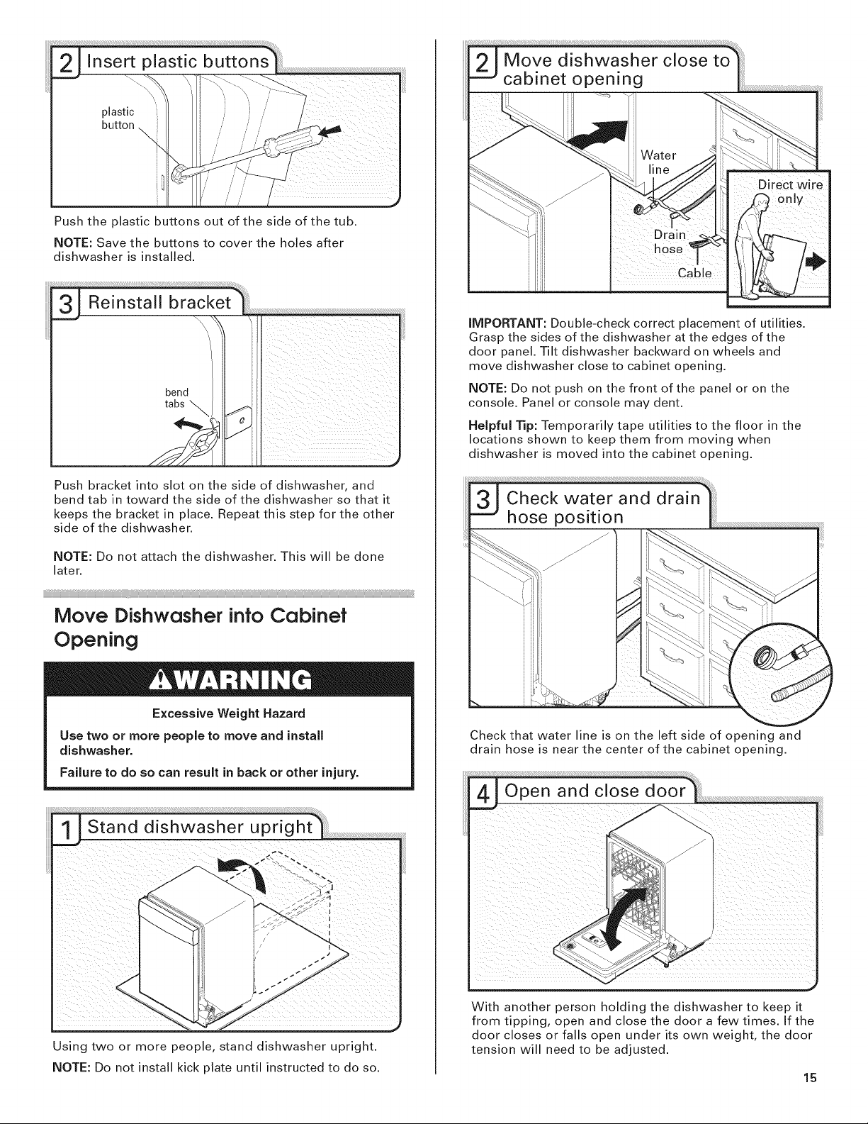
plastic _i
Pushtheplasticbuttonsoutofthesideofthetub.
NOTE:Savethebuttonstocovertheholesafter
dishwasherisinstalled.
Pushbracketintoslotonthesideofdishwasher,and
bendtabintowardthesideofthedishwashersothatit
keepsthebracketinplace.Repeatthisstepfortheother
sideofthedishwasher.
IMPORTANT: Double-check correct placement of utilities.
Grasp the sides of the dishwasher at the edges of the
door panel. Tilt dishwasher backward on wheels and
move dishwasher close to cabinet opening.
NOTE: Do not push on the front of the panel or on the
console. Panel or console may dent.
Helpful Tip: Temporarily tape utilities to the floor in the
locations shown to keep them from moving when
dishwasher is moved into the cabinet opening.
NOTE:Donotattachthedishwasher.Thiswillbedone
later.
Move Dishwasher into Cabinet
Opening
Excessive Weight Hazard
Use two or more people to move and install
dishwasher.
Failure to do so can result in back or other injury.
11Stand dishwasher uprighl '
Check that water line is on the left side of opening and
drain hose is near the center of the cabinet opening.
Using two or more people, stand dishwasher upright.
NOTE: Do not install kick plate until instructed to do so.
With another person holding the dishwasher to keep it
from tipping, open and close the door a few times. If the
door closes or falls open under its own weight, the door
tension will need to be adjusted.
15
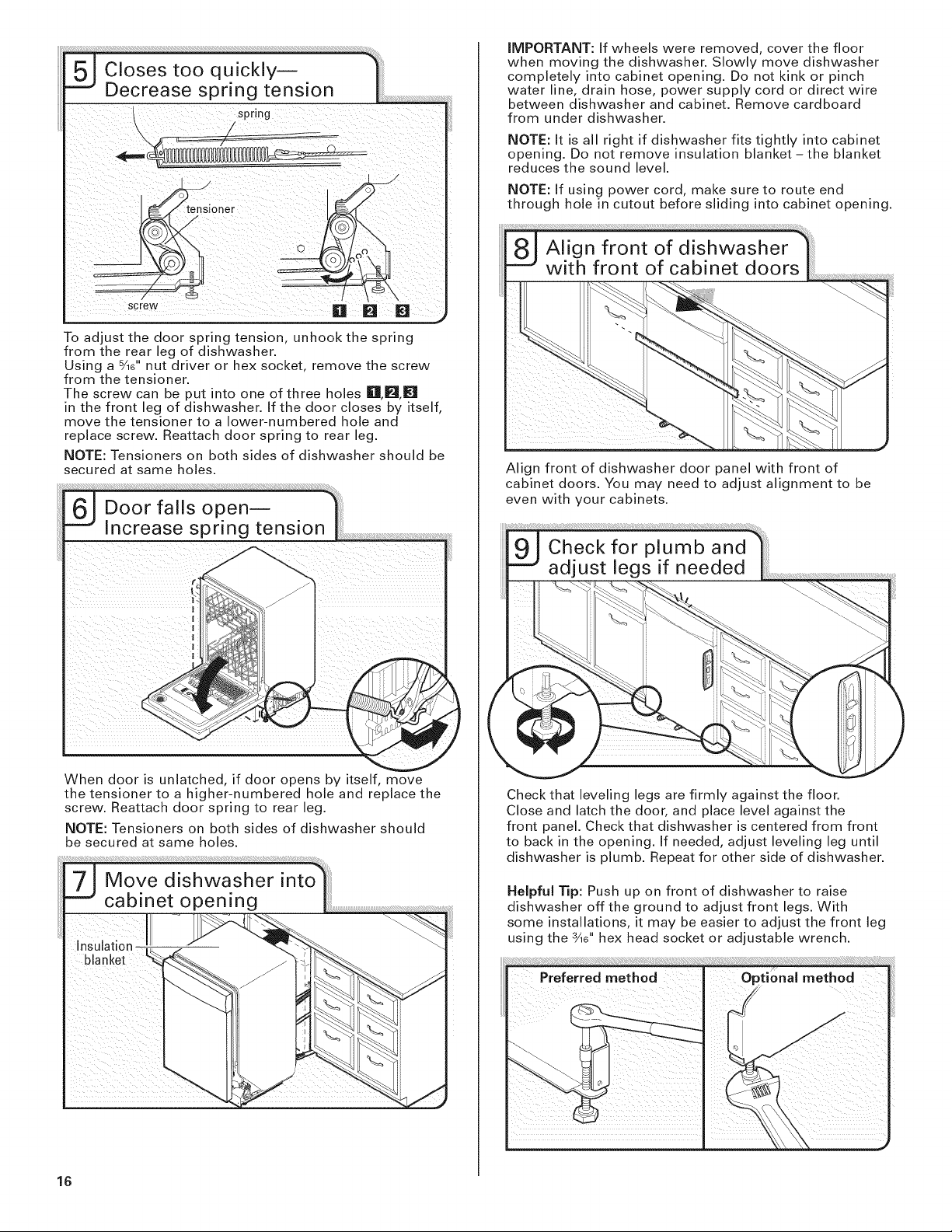
Toadjustthedoorspringtension,unhookthespring
fromtherearlegofdishwasher.
Usingas/16"nutdriverorhexsocket,removethescrew
fromthetensioner.
ThescrewcanbeputintooneofthreeholesIII1_1_t
in the front leg of dishwasher. If the door closes by itself,
move the tensioner to a lower-numbered hole and
replace screw. Reattach door spring to rear leg.
NOTE: Tensioners on both sides of dishwasher should be
secured at same holes.
IMPORTANT: If wheels were removed, cover the floor
when moving the dishwasher. Slowly move dishwasher
completely into cabinet opening. Do not kink or pinch
water line, drain hose, power supply cord or direct wire
between dishwasher and cabinet. Remove cardboard
from under dishwasher.
NOTE: It is all right if dishwasher fits tightly into cabinet
opening. Do not remove insulation blanket- the blanket
reduces the sound level.
NOTE: If using power cord, make sure to route end
through hole in cutout before sliding into cabinet opening.
Align front of dishwasher door panel with front of
cabinet doors. You may need to adjust alignment to be
even with your cabinets.
When door is unlatched, if door opens by itself, move
the tensioner to a higher-numbered hole and replace the
screw. Reattach door spring to rear leg.
NOTE: Tensioners on both sides of dishwasher should
be secured at same holes.
blanket
16
Check that leveling legs are firmly against the floor.
Close and latch the door, and place level against the
front panel. Check that dishwasher is centered from front
to back in the opening. If needed, adjust leveling leg until
dishwasher is plumb. Repeat for other side of dishwasher.
Helpful Tip: Push up on front of dishwasher to raise
dishwasher off the ground to adjust front legs. With
some installations, it may be easier to adjust the front leg
using the 3A6"hex head socket or adjustable wrench.
iiiiii_iii iiii_i/i i/i_iiii
Connect to Drain
drain
loop
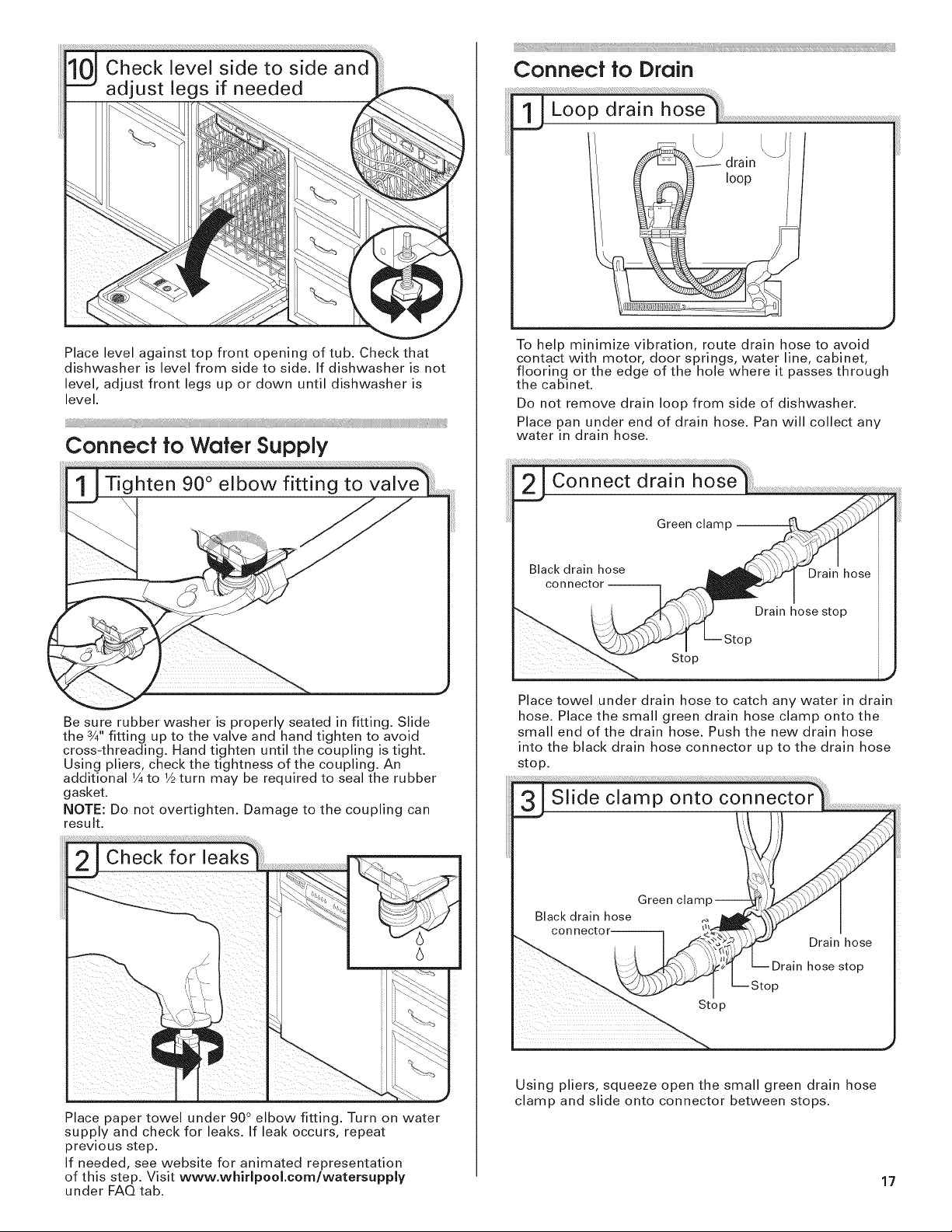
Placelevelagainsttopfrontopeningoftub.Checkthat
dishwasherislevelfromsidetoside.Ifdishwasherisnot
level,adjustfrontlegsupordownuntildishwasheris
level.
ii /i _iiiiiiiiiiiiiiiiiiiiiiiiiiiiiiiiiiiiiiiiiiiiiiiiiiiiiiiiiiiiiiiiiiiiiiiiiiiiiiiiiiiiii_i_i_iIiIiIiIi_
Connect to Water Supply
Be sure rubber washer is properly seated in fitting. Slide
the 3/4"fitting up to the valve and hand tighten to avoid
cross-threading. Hand tighten until the coupling is tight.
Using pliers, check the tightness of the coupling. An
additional 1/4to 1/2turn may be required to seal the rubber
gasket.
NOTE: Do not overtighten. Damage to the coupling can
result.
To help minimize vibration, route drain hose to avoid
contact with motor, door springs, water line, cabinet,
flooring or the edge of the hole where it passes through
the cabinet.
Do not remove drain loop from side of dishwasher.
Place pan under end of drain hose. Pan will collect any
water in drain hose.
Place towel under drain hose to catch any water in drain
hose. Place the small green drain hose clamp onto the
small end of the drain hose. Push the new drain hose
into the black drain hose connector up to the drain hose
stop.
Place paper towel under 90° elbow fitting. Turn on water
supply and check for leaks. If leak occurs, repeat
previous step.
If needed, see website for animated representation
of this step. Visit www.whirlpool.eom/watersupply
under FAQ tab.
Using pliers, squeeze open the small green drain hose
clamp and slide onto connector between stops.
17
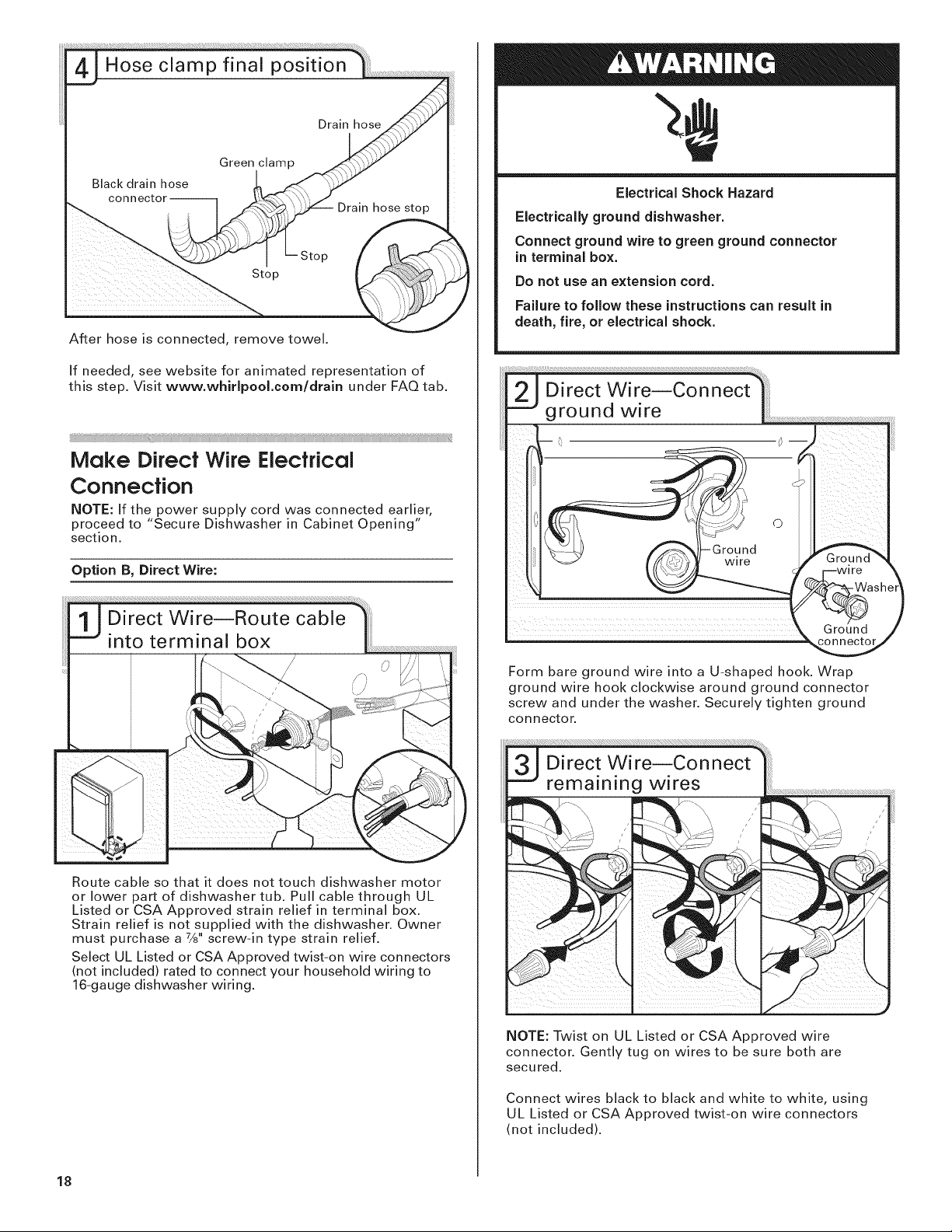
Afterhoseisconnected,removetowel.
Ifneeded,seewebsiteforanimatedrepresentationof
thisstep.Visitwww.whirlpool.eom/drainunderFAQtab.
Make DirectWire Electrical
Connection
NOTE: If the power supply cord was connected earlier,
proceed to "Secure Dishwasher in Cabinet Opening"
section.
Option B, Direct Wire:
Electrical Shock Hazard
Electrically ground dishwasher.
Connect ground wire to green ground connector
in terminal box.
Do not use an extension cord.
Failure to follow these instructions can result in
death, fire, or electrical shock.
2_jD¸I¸¸¸¸¸¸¸¸'rec(w¸i;e ¸¸¸c0¸¸¸nn¸¸¸¸¸¸e ¸¸ct¸¸'¸¸ ilili
ground wire
_._-_--0
<1
wlrl_lre I _ _'_."e _ _!
ash1
Ground/
Route cable so that it does not touch dishwasher motor
or lower part of dishwasher tub. Pull cable through UL
Listed or CSA Approved strain relief in terminal box.
Strain relief is not supplied with the dishwasher. Owner
must purchase a 7/8"screw-in type strain relief.
Select UL Listed or CSA Approved twist-on wire connectors
(not included) rated to connect your household wiring to
16-gauge dishwasher wiring.
Form bare ground wire into a U-shaped hook. Wrap
ground wire hook clockwise around ground connector
screw and under the washer. Securely tighten ground
connector.
NOTE: Twist on UL Listed or CSA Approved wire
connector. Gently tug on wires to be sure both are
secured.
Connect wires black to black and white to white, using
UL Listed or CSA Approved twist-on wire connectors
(not included).
18
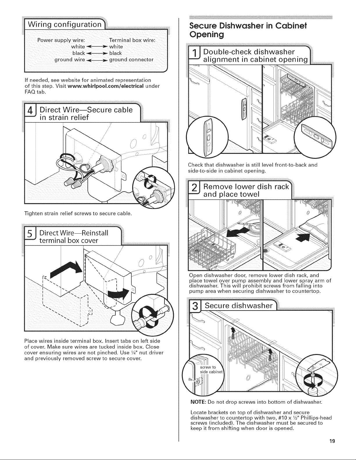
Wi ring co nf ig uratio n*_::
Power Supply wire: Terminal box wire:
If needed, see website for animated representation
of this step. Visit www.whMpool.eom/eleetrieal under
FAQ tab.
Secure Dishwasher inCabinet
Opening
Check that dishwasher is still level front-to-back and
side-to-side in cabinet opening,
Tighten strain relief screws to secure cable.
Place wires inside terminal box. Insert tabs on left side
of cover. Make sure wires are tucked inside box. Close
cover ensuring wires are not pinched. Use 1/4"nut driver
and previously removed screw to secure cover.
Open dishwasher door, remove lower dish rack, and
place towel over pump assembly and lower spray arm of
dishwasher. This will prohibit screws from falling into
pump area when securing dishwasher to countertop.
NOTE: Do not drop screws into bottom of dishwasher.
Locate brackets on top of dishwasher and secure
dishwasher to countertop with two, #10 x 1/2"Phillips-head
screws (included). The dishwasher must be secured to
keep it from shifting when door is opened.
19
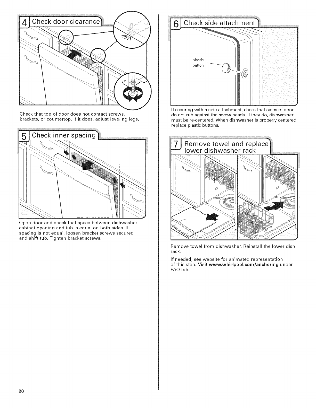
Checkthattopofdoordoesnotcontactscrews,
brackets,orcountertop.If itdoes,adjustlevelinglegs.
Opendoorandcheckthatspacebetweendishwasher
cabinetopeningandtubisequalonbothsides.If
spacingisnotequal,loosenbracketscrewssecured
andshifttub.Tightenbracketscrews.
Ifsecuringwithasideattachment,checkthatsidesofdoor
donotrubagainstthescrewheads.Iftheydo,dishwasher
mustbere-centered.Whendishwasherisproperlycentered,
replaceplasticbuttons.
Removetowelfromdishwasher.Reinstallthelowerdish
rack.
Ifneeded,seewebsiteforanimatedrepresentation
ofthisstep.Visitwww.whirlpool.corn/anchoringunder
FAQtab.
20
i ii iii_i i_iiiiiiiiii_
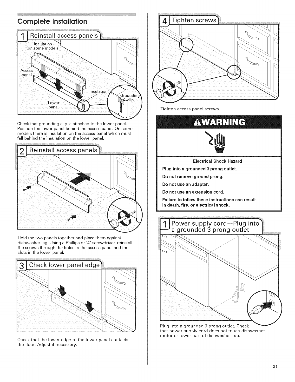
Complete Installation
Check that grounding clip is attached to the lower panel.
Position the lower panel behind the access panel. On some
models there is insulation on the access panel which must
fall behind the insulation on the lower panel,
Tighten access panel screws.
Hold the two panels together and place them against
dishwasher leg, Using a Phillips or 1A"screwdriver, reinstall
the screws through the holes in the access panel and the
slots in the lower panel,
Electrical Shock Hazard
Plug into a grounded 3 prong outlet.
Do not remove ground prong.
Do not use an adapter.
Do not use an extension cord.
Failure to follow these instructions can result
in death, fire, or electrical shock.
Check that the lower edge of the lower panel contacts
the floor. Adjust if necessary.
Plug into a grounded 3 prong outlet. Check
that power supply cord does not touch dishwasher
motor or lower part of dishwasher tub.
21
Reconnect Power
Re;oine;;;owe;
::onne o:'0c,"co,iat
Check Operation
[_ Read the Dishwasher User Instructions that came
with your dishwasher.
[_1 Check that all parts have been installed and no steps
were skipped. Check that you have all tools used.
Add#ional Tips
Expect longer wash times. Your new dishwasher will
average 2-3 hours per load, but use nearly 40% less
energy than older models. Designed with a low wattage,
low energy consumption motor, your dishwasher
washes longer to ensure exceptional cleaning. Certain
models are equipped with an optical water sensor so the
first cycle will run longer to calibrate to optical sensor.
Selecting certain options could increase cycle time past
3.5 hours.
Rinse Aid is necessary for good drying results:
This dishwasher is designed to be used with rinse aid for
good drying performance and controlling hard water
deposit buildup. Energy efficient dishwashers use less
water and energy, so they depend on the water sheeting
action of rinse aid for good drying performance.
[_1 Start dishwasher and allow it to complete the shortest
wash cycle. After the first 2 minutes unlatch door,
wait 5 seconds, then open door. Check to see that
there is water in the bottom of the dishwasher tub.
Check that dishwasher is working properly.
If the dishwasher is not working properly, disconnect
power or unplug dishwasher and see "If Dishwasher
Does Not Operate" section.
............................................................................................................................................................
Start/Resume light may flash:
When pressing Start/Resume, you must make sure the
door is closed within 3 seconds. If you do not close the
door within 3 seconds, the Start/Resume light will flash
until you press it again. (You must also do this when
adding a dish during the middle of a cycle.)
NOTE: If a braided supply hose is used, replace inlet hose
after 5 years to reduce the risk of hose failure. Record
hose installation or replacement dates on the hose for
future reference.
If Dishwasher Does Not Operate
First try the solutions suggested here to possibly avoid
the cost of a service call.
Has the circuit breaker tripped or the house fuse
blown?
Is the door closed tightly and latched?
Has the cycle been set correctly to start the
dishwasher?
Is the water turned on?
If none of these possible solutions work, call
1-800-422-1230, or in Canada, call 1-800-807-6777.
22

23
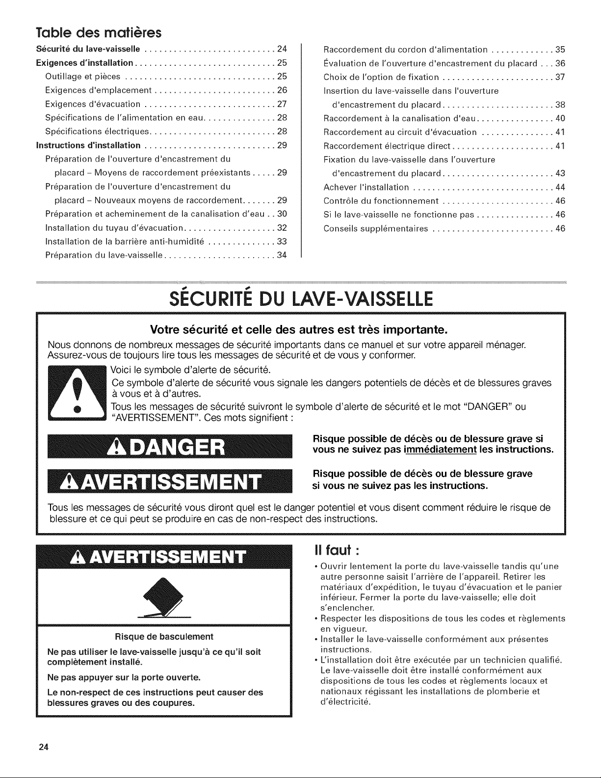
Table des rnafi@res
Securite du lave-vaisselle ........................... 24
Exigences d'installation ............................. 25
Outillage et pieces ............................... 25
Exigences d'emplacement ......................... 26
Exigences d'evacuation ........................... 27
Specifications de I'alimentation en eau ............... 28
Specifications electriques .......................... 28
Instructions d'installation ........................... 29
Preparation de I'ouverture d'encastrement du
placard - Moyens de raccordement preexistants ..... 29
Preparation de I'ouverture d'encastrement du
placard - Nouveaux moyens de raccordement ....... 29
Preparation et acheminement de la canalisation d'eau .. 30
Installation du tuyau d'evacuation ................... 32
Installation de la barriere anti-humidite .............. 33
Preparation du lave-vaisselle ....................... 34
Raccordement du cordon d'alimentation ............. 35
Ftvaluation de I'ouverture d'encastrement du placard ... 36
Choix de I'option de fixation ....................... 37
Insertion du lave-vaisselle dans I'ouverture
d'encastrement du placard ....................... 38
Raccordement a la canalisation d'eau ................ 40
Raccordement au circuit d'evacuation ............... 41
Raccordement electrique direct ..................... 41
Fixation du lave-vaisselle dans I'ouverture
d'encastrement du placard ....................... 43
Achever I'installation ............................. 44
Contr61e du fonctionnement ....................... 46
Si le lave-vaisselle ne fonctionne pas ................ 46
Conseils supplementaires ......................... 46
Votre s@curit_ et celle des autres est tr_s importante.
Nous donnons de nombreux messages de securit6 importants dans ce manuel et sur votre appareil menager.
Assurez-vous de toujours lire tous les messages de securite et de vous y conformer.
Voici le symbole d'alerte de securit&
Ce symbole d'alerte de securite vous signale les dangers potentiels de deces et de blessures graves
A vous et A d'autres.
Tousles messages de securite suivront le symbole d'alerte de securite et le mot "DANGER" ou
"AVERTISSEMENT". Ces mots signifient :
Risque possible de d_c_s ou de blessure grave si
vous ne suivez pas imm_diatement les instructions.
Risque possible de d_c_s ou de blessure grave
si vous ne suivez pas les instructions.
Tousles messages de securite vous diront quel est le danger potentiel et vous disent comment reduire le risque de
blessure et ce qui peut se produire en cas de non-respect des instructions.
II foul.
, Ouvrir lentement la porte du lave-vaisselle tandis qu'une
autre personne saisit I'arriere de I'appareil. Retirer les
materiaux d'expedition, le tuyau d'evacuation et le panier
inferieur. Fermer la porte du lave-vaisselle; elle doit
s'enclencher.
, Respecter les dispositions de tousles codes et r_glements
Risque de basculement
Ne pas utiliser le lave=vaisselle jusqu'a ce qu'it soit
completement install&
Ne pas appuyer sur la porte ouverte.
Le non=respect de ces instructions peut causer des
blessures graves ou des coupures.
en vigueur.
, Installer le lave-vaisselle conformement aux presentes
instructions.
, L'installation doit _tre ex_cutee par un technicien qualifi&
Le lave-vaisselle doit &tre installe conformement aux
dispositions de tous les codes et reglements Iocaux et
nationaux regissant les installations de plomberie et
d'electricit&
24
EXIGENCES D'INSTALLATION
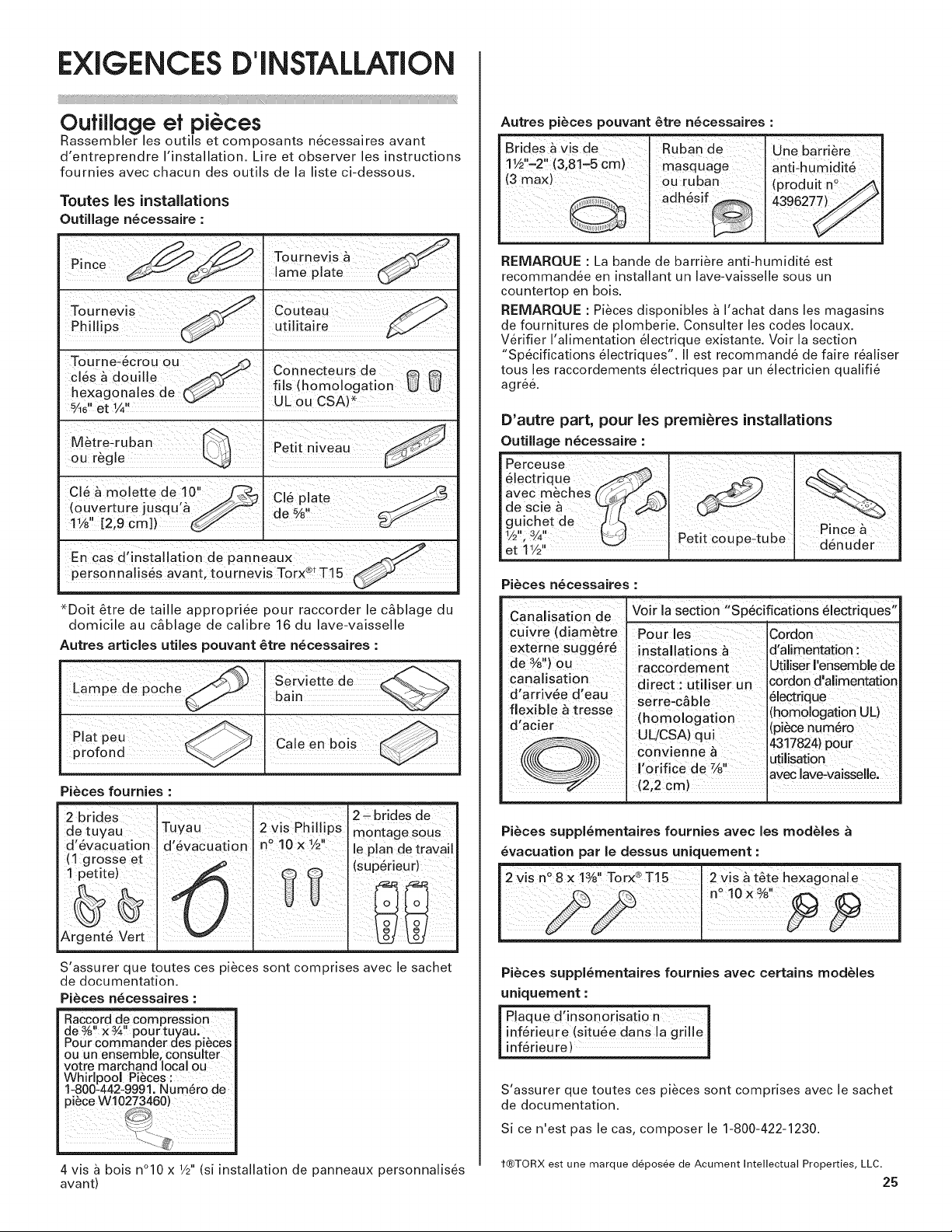
Oufillage ef pi@ces
Rassembler les outils et composants necessaires avant
d'entreprendre I'installation. L_ireet observer les nstructions
fournies avec chacun des outils de a liste ci-dessous.
"routes les installations
Outillage necessaire :
nnce I lame plate
Tourne-_crou ou _ _
cl_s _ douille _ Connecteurs de A
, , . /_._ ills (homologation U U
nexagonales ae [Y_/ ,,, _._^,.
5Ae"et 1/2' "_" . UL OU L, bA)
Cl_ & molette de 10" 2_ C!6 -late
(ouverture jusqu a J_,/'-_ I de % _r_'J_
1 ii
1½ [2,9 cm]) _1
En cas d'installation de panneaux
personnalis6s avant, tournevis Torx®tT15
*Doit 6tre de taille appropriee pour raccorder le c_blage du
domicile au cSblage de calibre 16 du lave-vaisselle
Autres articles utiles pouvant _tre n_cessaires :
Lampe de PoChe
Plat peu
profond
Pi_ces fournies :
• '" _Jll
Autres pi_ces pouvant _tre n_cessaires
Une ba[ri_re i
antPhumidit_ I
(pr0duit n° /_1
REMARQUE : La bande de barri_re anti-humidit6 est
recommand6e en installant un lave-vaisselle sous un
countertop en bois.
REMARQUE : Pi_ces disponibles a I'achat dans les magasins
de fournitures de plomberie. Consulter les codes Iocaux.
V6rifier I'alimentation 61ectrique existante. Voir la section
"Sp6cifications _lectriques". II est recommand_ de faire r_aliser
tousles raccordements _lectriques par un _lectricien qualifi6
agr6&
D'autre part, pour les premieres installations
Outillage n_cessaire :
PerceUSe
_lectrique
avec m#ches
de scie
guichet de
1/2'!,
et t 1/2'
Pi_ces n_cessaires :
Canalisation de Voir la section "Sp6cifications 61ectriques"
cuwre (dlametre Pour les Cordon
externe sugg_r_ installations _ 'd'alimentation :
de%,) ou raccordement utiliser I'ensemble de
Canal!sation direct; utiliser un cordon d'al!mentation
d arr v_e d eau "^_ _ ectrque
flexible a tresse ,. :; [homo onat on UL)
,4,._..;_ momologat_on ,., _ ;
u _,_, H! /P_A_ -. : Itplece numero
/////If --._\_,'t_:\I conv enne a ili i n
_{_t _l_m'_ . " " 7 ;; ul: sal:0
__/;/ laveclave:vaisselle,
_--"_" (2,2 cm)
. I
. serre-cab e
i . . 14317824)pour
I orifice de %
de tuyau montage S0Us
d 6vacuation d,6vacuat On n° 10xY2 leplan detravail
(1 grosse et (sup6rieur)
1 petite)
Argent6 Vert
S'assurer que toutes ces pi_ces sont comprises avec le sachet
de documentation.
Pi_ces n_cessaires :
Raccord de compression
de%, x¾ pour tuyau.
Pour commander des pi_ces
ou un ensemble, consulter
votre marchand Ioca ou
Whirlpool Pi_ces :
1-800-442-9991. Num_ro de:
4 vis a bois n°10 x W' (si installation de panneaux personnalis_s t®TORX est une marque d_pos_e de Acument Intellectual Properties, LLC.
avant) 25
TuyaU' 2 Vis Phill,!ps 2 _ brides de
Pi6ces suppl6mentaires fournies avec les modules
_vacuation par le dessus uniquement :
n_ 10 x %"
2 Vis n°8 X 1%" Torx® TI 5 2 vis & t6te hexagonal e
Pi_ces suppl_mentaires fournies avec certains modules
uniquement :
Plaque dqnsonOrisatio n I
infgrieure [situ_e dans la grille I
i --
infgrieure) ........ J
S'assurer que toutes ces pi_ces sont comprises avec le sachet
de documentation.
Si ce n'est pas le cas, composer le 1-800-422-1230.
Exigences d'emplacemenf
Une source d'electricite avec liaison a la terre est
n6cessaire.
Ne pas placer de canalisation d'evacuation, canalisation
d'eau ou cSblage electrique _ un endroit oQ cela susciterait
interference ou contact avec les pieds ou le moteur du lave-
vaissel le.
I'emplacement d'installation du lave-vaisselle, on doit
pouvoir etablir le d(}gagement approprie entre le moteur et
le plancher. Le moteur ne doit pas toucher le plancher.
Ne pas installer le lave-vaisselle sur de la moquette.
Abriter du gel le lave-vaisselle et les canalisations d'eau qui
I'alimentent. La garantie de I'appareil ne couvre pas les
dommages imputables au gel.
Un ensemble de panneau lateral est disponible chez votre
marchand pour I'installation du lave-vaisselle a I'extremite
d'une rangee de placards.
Une barriere anti-humidite (produit n° 4396277) est
disponible chez votre revendeur pour I'installation de
I'appareil sous le plan de travail. Composer le
1-8OO-422-1230 pour commander.
Inspecter I'emplacement d'installation du lave-vaisselle. II
doit comporter les caracteristiques suivantes :
facilite d'acc_s aux canalisations d'eau et d'egout eta la
source d'electricit&
acc_s facile pour le chargement et dechargement de la
vaisselle.
Dans le cas d'installation dans un angle, on doit pouvoir
etablir un degagement minimal de 2" (5,1 cm) entre le
c6te de la porte du lave-vaisselle et le mur ou le
placard.
ouverture carree offrant I'esth6tique appropriee et
permettant un fonctionnement correct.
facade des placards perpendiculaire au plancher.
plancher horizontal et plat. (S'il y a un ecart de niveau
sur le plancher entre I'avant et I'arriere de
I'emplacement d'installation, il pourrait &tre n_cessaire
d'utiliser des cales pour etablir I'aplomb de I'appareil).
Conseil utile : Veiller _ mesurer correctement les
dimensions et s'assurer que le lave-vaisselle est
d'aplomb si le plancher dans I'ouverture d'encastrement
du lave-vaisselle est irregulier (par exemple, le
rev&tement de sol ne pen_tre que partiellement dans
I'ouverture).
REMARQUE : Pour eviter tout deplacement des cales
durant le fonctionnement du lave-vaisselle, les cales
doivent &tre solidement fixees au plancher.
Si le lave-vaisselle ne doit pas &tre utilise pendant une
periode prolongee ou s'il est laisse a un endroit qui
pourrait &tre expose au gel, veiller _ faire executer les
operations de pre-hivernage par un technicien competent.
Veiller ace que les canalisations d'eau et d'evacuation et
les c_bles electriques se trouvent dans les limites de la
zone marqu6e en gris illustree dans la section "Dimensions
du produit et de I'ouverture d'encastrement du placard".
26
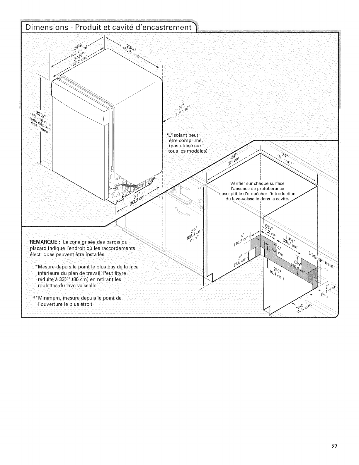
REMARQUE : La,zone gris6e des parois du
placard indique Iendroit oQ les raccordements
61ectriques peuvent 6tre install6s.
*Mesure depuis le point le plus bas de la face
inf6rieure du plan de travail. Peut _tyre
r6duite _ 33%" 86 cm en ret( ) irant les
roulettes du lave-vaisselle.
1'_C
*L'isolant peut
Pabsence de protuberance
susceptible d'emp_cher Pintroduction
du lave-vaisselie dans la cavit6.
**Minimum, mesure depuis le point de
I'ouverture le plus 6troit
27
E×igences d' vacuafion
Sp6cificafions de I'alimenfafion en eau
Un tuyau d'evacuation neuf est fourni avec le lave-
vaisselle. Si ce tuyau n'est pas suffisamment long, utiliser
un tuyau d'evacuation neuf de Iongueur maximale de 12'
(3,7 m) (piece numero 3385556) qui satisfait les crit_res
des normes de test AHAM/IAPMO en vigueur, est resistant
la chaleur et aux detergents, et peut &tre connecte au
raccord d'evacuation de 1" (2,5 cm) du lave-vaisselle.
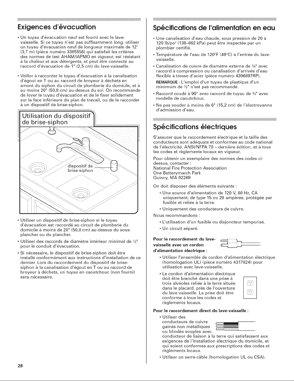
Veiller a raccorder le tuyau d'evacuation _ la canalisation
d'egout en T ou au raccord de broyeur a dechets en
amont du siphon du circuit de plomberie du domicile, et
au moins 20" (50,8 cm) au-dessus du sol. On recommande
de lover le tuyau d'evacuation et de le fixer solidement
sur la face inferieure du plan de travail, ou de le raccorder
un dispositif de brise-siphon.
, Une canalisation d'eau chaude, sous pression de 20
120 Ib!po 2 (138-862 kPa) peut &tre inspectee par un
plombier certifi&
, Temperature de I'eau de 120°F (49°C) a I'entree du lave-
vaisselle.
, Canalisation de cuivre de diam_tre externe de 3/8"avec
raccord a compression ou canalisation d'arrivee d'eau
flexible a tresse d'acier (piece numero 4396897RP).
REMARQUE: L'emploi d'un tuyau de plastique d'un
minimum de 1/2"n'est pas recommande.
Raccord coude _ 90° avec raccord de tuyau de 3/4"avec
rondelle de caoutchouc.
Ne pas souder a moins de 6" (15,2 cm) de I'electrovanne
d'admission d'eau.
Sp6ciflcafions@lecfriques
S'assurer que le raccordement electrique et la taille des
conducteurs sont adequats et conformes au code national
de I'electricite, ANSI/NFPA 70 - derniere edition, et a tous
les codes et r_glements Iocaux en vigueur.
Pour obtenir un exemplaire des normes des codes ci-
dessus, contacter :
National Fire Protection Association
One Batterymarch Park
Quincy, MA 02269
Utiliser un dispositif de brise-siphon si le tuyau
d'evacuation est raccorde au circuit de plomberie du
domicile a moins de 20" (50,8 cm) au-dessus du sous-
plancher ou du plancher.
Utiliser des raccords de diam_tre interieur minimal de 1/2"
pour le conduit d'evacuation.
Si necessaire, le dispositif de brise-siphon dolt &tre
installe conformement aux instructions d'installation de ce
dernier. Lors du raccordement du dispositif de brise-
siphon _ la canalisation d'egout en T ou au raccord de
broyeur _ dechets, un tuyau en caoutchouc (non fourni)
sera n6cessaire.
28
On dolt disposer des elements suivants :
Une source d'alimentation de 120 V, 60 Hz, CA
uniquement, de type 15 ou 20 amperes, protegee par
fusible et reliee a la terre.
• Uniquement des conducteurs de cuivre.
Nous recommandons :
L'utilisation d'un fusible ou disjoncteur temporis&
Un circuit separ&
Pour le raccordement du lave-
vaisselle avec un cordon
d'alimentation electrique :
* Utiliser I'ensemble de cordon d'alimentation electrique
(homologation UL) (piece numero 4317824) pour
utilisation avec lave-vaisselle.
Le cordon d'alimentation electrique
doit _tre branch_ dans une prise a
trois alveoles reliee a la terre situ_e
dans le placard, pros de I'ouverture
du lave-vaisselle. La prise doit &tre
conforme a tous les codes et
r_glements Iocaux.
Pour le raccordernent direct du lave-vaisseHe :
, Utiliser des
conducteurs de cuivre
gain6s non metalliques
ou blindes souples avec
conducteur de liaison & la terre qui satisfassent aux
exigences de I'installation electrique du domicile, et
qui soient conformes aux prescriptions des codes et
r_glements Iocaux.
* Utiliser un serre-c_ble (homologation UL ou CSA).
iNSTRUCTiONSD'INSTALLATION
Risque de choc 61ectrique
Interrompre I'alJmentation 61ectrique avant d'installer
le lave=vaisselle (au niveau du tableau de distribution -
fusible ou disjoncteur).
Le non=respect de cette instruction peat causer
un d6c_s ou on choc 61ectrique.
de courant _lectrique !
Avant d'entreprendre I,in_allation du !ave4vai_ll e, i
interrompre I'alimentation du circuit au niveau du
boitier de distribution (fusible ou disjoncteur),
Fer,meture de I,alimentation en ea
Fermer I alimentation en eau raCC0rd_e au lave_vaissellel
I Fer
...........................................................................................................................................iiiiiiiiiilD;¸i;¸il,i,i_;i,i:;ii;¸ii¸;i;¸ii¸;i;¸ii¸;i;¸ii¸;i;¸ii¸;i;¸ii¸;i;¸ii¸;i;¸ii¸;i;¸ii¸;i;¸ii¸;;i;¸ii,lii¸ii,lii¸ii,lii¸ii,lii¸ii,lii¸ii,li¸ii¸;;i;¸ili:;i;i;¸ili:;i;i;¸ili:;i;i;¸ili:;i;i;¸ili:;ii;¸ii¸;i;¸ii¸;i;¸ii¸;i;¸ii¸;i;¸ii¸;i;¸ii¸;i;¸ii¸;i;¸ii¸;i;¸ii¸;i;¸ii¸;i;¸ii¸;i;¸ii¸;i;¸ii¸;i;¸ii¸;i;¸ii¸;i;¸ii¸;i;¸ii¸;i;¸ii¸;i;¸ii¸;i;¸ii¸;i;¸ii¸;i;¸ii¸;i;¸ii¸;i;¸ii¸;i;¸ii¸;i;¸ii¸;i;¸ii¸;i;¸ii¸;i;¸ii¸;i;¸ii¸;i;¸ii¸;i;¸ii¸;i;¸ii¸;i;¸i¸
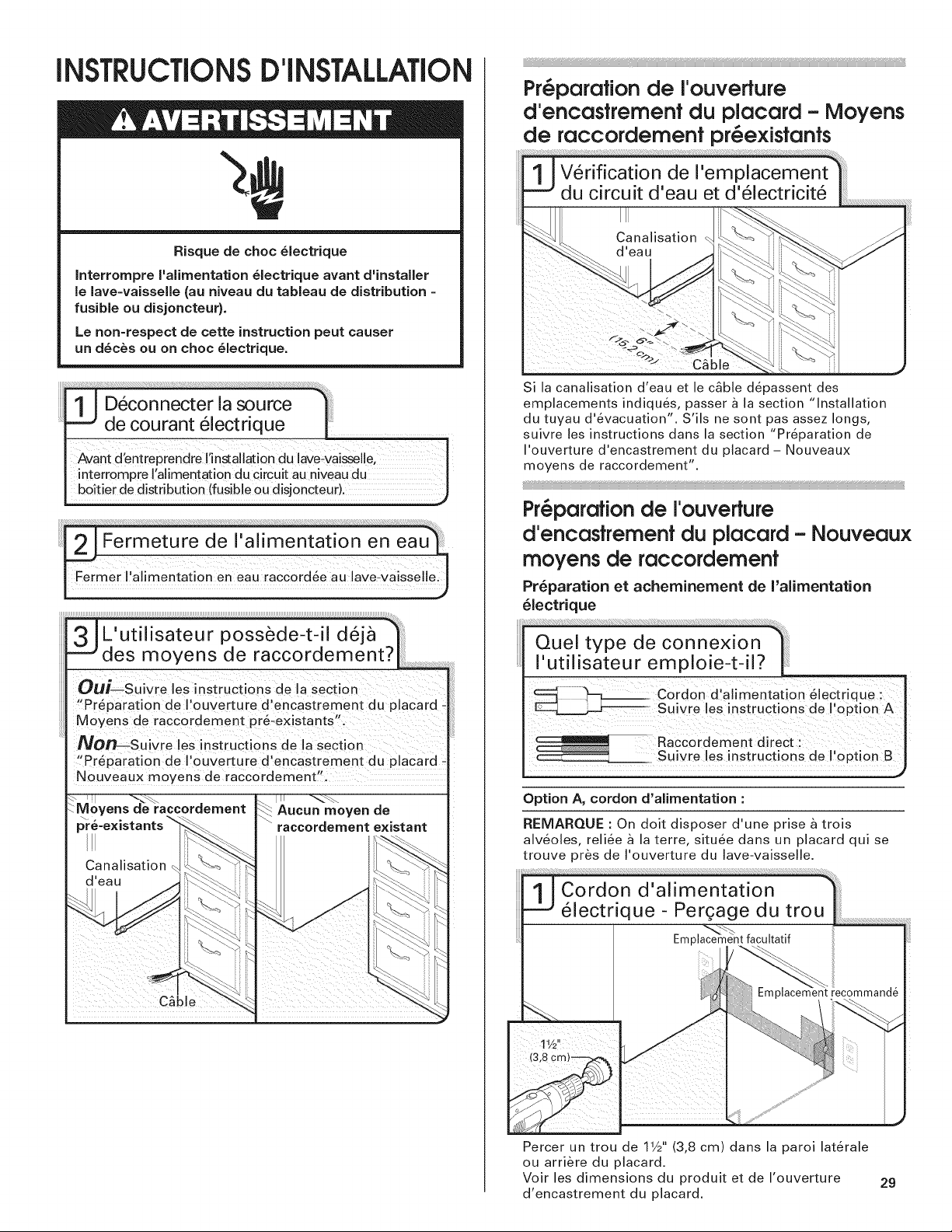
Pr@paration de I'ouverture
d'encastremenf du placard - Moyens
de raccordement pr_existants
C_ble
Si la canalisation d'eau et le c_ble d6passent des
emplacements indiqu6s, passer a la section "Installation
du tuyau d'6vacuation". S'ils ne sont pas assez longs,
suivre los instructions dans la section "Pr6paration de
I'ouverture d'encastrement du placard - Nouveaux
moyens de raccordement".
Pr_parafion de I'ouverfure
d'encasfremenf du placard - Nouveaux
moyens de raccordemenf
Pr6paration et acheminement de I'alimentation
61ectrique
L'utilisateur possede-t-il deja
des moyens de raccordement?
OU_Suivre I_S iJlstruCtions de la section
_!Pr_,paration de I,ouverture d,encastrement du plaCard -
Moyens de racc0rdement pr_existants_';
No_suivre los instructions de la section
"Preparation de I'ouve_ure d'encastrement du placard
Nouveaux m0yens de raccordement
I utilisateur emploil-t-il? I_
cordon d alimentati0n &leCtrique :
Suivre !es instructions de I option A I
Raccordement direct : J
Suiv[e !as inst[uctions de !'°pti0n B_
Option A, cordon d'alimentation :
RENIARQUE : On dolt disposer d'une prise a trois
alveoles, reliee a la terra, situ_e dans un placard qui se
trouve pros de I'ouverture du lave-vaisselle.
I
Percer un trou de 1V2"(3,8 cm) dans la paroi laterale
ou arriere du placard.
Voir les dimensions du produit et de I'ouverture
d'encastrement du placard.
29
 Loading...