


CONSUMER SERVICES TECHNICAL |
L-79 |
EDUCATION GROUP PRESENTS |
ELECTRONIC
GAS & ELECTRIC
DRYERS
MODELS: WED8300SW, WED8500SR
WGD8300SW, WGD8500SR
JOB AID
Part No. 8178559
FORWARD
This Whirlpool Job Aid, “Duet Sport™ Electronic Gas & Electric Dryers” (Part No. 8178559), provides the technician with information on the installation, operation, and service of the Duet Sport™ Electronic Gas & Electric Dryers. For specific information on the model being serviced, refer to the “Use and Care Guide,” or “Tech Sheet” provided with the dryer.
The Wiring Diagrams used in this Job Aid are typical and should be used for training purposes only. Always use the Wiring Diagram supplied with the product when servicing the unit.
GOALS AND OBJECTIVES
The goal of this Job Aid is to provide information that will enable the service technician to properly diagnose malfunctions and repair the Duet Sport™ Electronic Gas & Electric Dryers.
The objectives of this Job Aid are to:
•Understand and follow proper safety precautions.
•Successfully troubleshoot and diagnose malfunctions.
•Successfully perform necessary repairs.
•Successfully return the dryer to its proper operational status.
WHIRLPOOL CORPORATION assumes no responsibility for any repairs made on our products by anyone other than Authorized Service Technicians.
Copyright © 2006, Whirlpool Corporation, Benton Harbor, MI 49022
- ii -

TABLE OF CONTENTS
Page
GENERAL . . . . . . . . . . . . . . . . . . . . . . . . . . . . . . . . . . . . . . . . . . . . . . . . . . . . . . . . . . . . . . 1-1
Dryer Safety . . . . . . . . . . . . . . . . . . . . . . . . . . . . . . . . . . . . . . . . . . . . . . . . . . . . . . . . . . . 1-1
Model & Serial Number Designations . . . . . . . . . . . . . . . . . . . . . . . . . . . . . . . . . . . . . . . . 1-2
Model & Serial Number Label And Tech Sheet Locations. . . . . . . . . . . . . . . . . . . . . . . . . 1-3
Specifications . . . . . . . . . . . . . . . . . . . . . . . . . . . . . . . . . . . . . . . . . . . . . . . . . . . . . . . . . . 1-4
INSTALLATION INFORMATION . . . . . . . . . . . . . . . . . . . . . . . . . . . . . . . . . . . . . . . . . . . . . 2-1
Installation Instructions . . . . . . . . . . . . . . . . . . . . . . . . . . . . . . . . . . . . . . . . . . . . . . . . . . . 2-1
PRODUCT OPERATION . . . . . . . . . . . . . . . . . . . . . . . . . . . . . . . . . . . . . . . . . . . . . . . . . . . 3-1
Dryer Use . . . . . . . . . . . . . . . . . . . . . . . . . . . . . . . . . . . . . . . . . . . . . . . . . . . . . . . . . . . . . 3-1
Dryer Care. . . . . . . . . . . . . . . . . . . . . . . . . . . . . . . . . . . . . . . . . . . . . . . . . . . . . . . . . . . . . 3-9
Troubleshooting. . . . . . . . . . . . . . . . . . . . . . . . . . . . . . . . . . . . . . . . . . . . . . . . . . . . . . . . .3-11
COMPONENT ACCESS . . . . . . . . . . . . . . . . . . . . . . . . . . . . . . . . . . . . . . . . . . . . . . . . . . 4-1
Component Locations . . . . . . . . . . . . . . . . . . . . . . . . . . . . . . . . . . . . . . . . . . . . . . . . . . . . 4-1
Removing The Console And The Console Electronics Assembly . . . . . . . . . . . . . . . . . . . 4-2
Removing The Machine Control Electronics . . . . . . . . . . . . . . . . . . . . . . . . . . . . . . . . . . . 4-4
Removing The Door Switch. . . . . . . . . . . . . . . . . . . . . . . . . . . . . . . . . . . . . . . . . . . . . . . . 4-5
Removing The Moisture Sensor . . . . . . . . . . . . . . . . . . . . . . . . . . . . . . . . . . . . . . . . . . . . 4-6
Removing The Drum Light Socket. . . . . . . . . . . . . . . . . . . . . . . . . . . . . . . . . . . . . . . . . . . 4-7
Removing The Front Panel . . . . . . . . . . . . . . . . . . . . . . . . . . . . . . . . . . . . . . . . . . . . . . . . 4-8
Removing The Thermal Fuse & Exhaust Thermistor . . . . . . . . . . . . . . . . . . . . . . . . . . . . 4-9
Removing The Belt & Drum, And Rollers . . . . . . . . . . . . . . . . . . . . . . . . . . . . . . . . . . . . 4-10
Removing The Drive Motor And Belt Switch . . . . . . . . . . . . . . . . . . . . . . . . . . . . . . . . . . 4-12
Removing The Ignitor, Flame Sensor, High-Limit Thermostat,
And Thermal Cutoff (Gas Models Only). . . . . . . . . . . . . . . . . . . . . . . . . . . . . . . . . . . . 4-14
Removing The Gas Burner Assembly Coils . . . . . . . . . . . . . . . . . . . . . . . . . . . . . . . . . . 4-16
Removing The Heater, High-Limit Thermostat, And Thermal Cutoff
(Electric Models Only) . . . . . . . . . . . . . . . . . . . . . . . . . . . . . . . . . . . . . . . . . . . . . . . . . 4-17
Removing The Dryer Door. . . . . . . . . . . . . . . . . . . . . . . . . . . . . . . . . . . . . . . . . . . . . . . . 4-18
COMPONENT TESTING . . . . . . . . . . . . . . . . . . . . . . . . . . . . . . . . . . . . . . . . . . . . . . . . . . . 5-1
Moisture Sensor . . . . . . . . . . . . . . . . . . . . . . . . . . . . . . . . . . . . . . . . . . . . . . . . . . . . . . . . 5-1
Door Switch. . . . . . . . . . . . . . . . . . . . . . . . . . . . . . . . . . . . . . . . . . . . . . . . . . . . . . . . . . . . 5-2
Thermal Fuse . . . . . . . . . . . . . . . . . . . . . . . . . . . . . . . . . . . . . . . . . . . . . . . . . . . . . . . . . . 5-3
Exhaust Thermistor . . . . . . . . . . . . . . . . . . . . . . . . . . . . . . . . . . . . . . . . . . . . . . . . . . . . . . 5-4
Drive Motor . . . . . . . . . . . . . . . . . . . . . . . . . . . . . . . . . . . . . . . . . . . . . . . . . . . . . . . . . . . . 5-5
Flame Sensor . . . . . . . . . . . . . . . . . . . . . . . . . . . . . . . . . . . . . . . . . . . . . . . . . . . . . . . . . . 5-6
High-Limit Thermostat & Thermal Cutoff (Gas Dryers Only). . . . . . . . . . . . . . . . . . . . . . . 5-6
Burner Ignitor. . . . . . . . . . . . . . . . . . . . . . . . . . . . . . . . . . . . . . . . . . . . . . . . . . . . . . . . . . . 5-7
Gas Burner Coils. . . . . . . . . . . . . . . . . . . . . . . . . . . . . . . . . . . . . . . . . . . . . . . . . . . . . . . . 5-7
Thermal Cutoff (Electric Dryers Only) . . . . . . . . . . . . . . . . . . . . . . . . . . . . . . . . . . . . . . . . 5-8
Heater (Electric Dryers Only). . . . . . . . . . . . . . . . . . . . . . . . . . . . . . . . . . . . . . . . . . . . . . . 5-8
- iii -

Page
DIAGNOSTICS & TROUBLESHOOTING . . . . . . . . . . . . . . . . . . . . . . . . . . . . . . . . . . . . . . 6-1
Diagnostic Guide. . . . . . . . . . . . . . . . . . . . . . . . . . . . . . . . . . . . . . . . . . . . . . . . . . . . . . . . 6-1
Diagnostic Tests . . . . . . . . . . . . . . . . . . . . . . . . . . . . . . . . . . . . . . . . . . . . . . . . . . . . . . . . 6-1
Display Fault Codes . . . . . . . . . . . . . . . . . . . . . . . . . . . . . . . . . . . . . . . . . . . . . . . . . . . . . 6-4
Troubleshooting Guide . . . . . . . . . . . . . . . . . . . . . . . . . . . . . . . . . . . . . . . . . . . . . . . . . . . 6-5
Troubleshooting Tests . . . . . . . . . . . . . . . . . . . . . . . . . . . . . . . . . . . . . . . . . . . . . . . . . . . . 6-6
Removing The Toe Panel . . . . . . . . . . . . . . . . . . . . . . . . . . . . . . . . . . . . . . . . . . . . . . . . 6-15
Accessing & Removing The Electronic Assemblies. . . . . . . . . . . . . . . . . . . . . . . . . . . . . 6-15
Removing The Back Panel . . . . . . . . . . . . . . . . . . . . . . . . . . . . . . . . . . . . . . . . . . . . . . . 6-17
WIRING DIAGRAMS. . . . . . . . . . . . . . . . . . . . . . . . . . . . . . . . . . . . . . . . . . . . . . . . . . . . . . . 7-1
Electric Dryer. . . . . . . . . . . . . . . . . . . . . . . . . . . . . . . . . . . . . . . . . . . . . . . . . . . . . . . . . . . 7-1
Gas Dryer . . . . . . . . . . . . . . . . . . . . . . . . . . . . . . . . . . . . . . . . . . . . . . . . . . . . . . . . . . . . . 7-2
- iv -
GENERAL
DRYER SAFETY
Your safety and the safety of others is very important.
We have provided many important safety messages in this Job Aid and on the appliance. Always read and obey all safety messages.
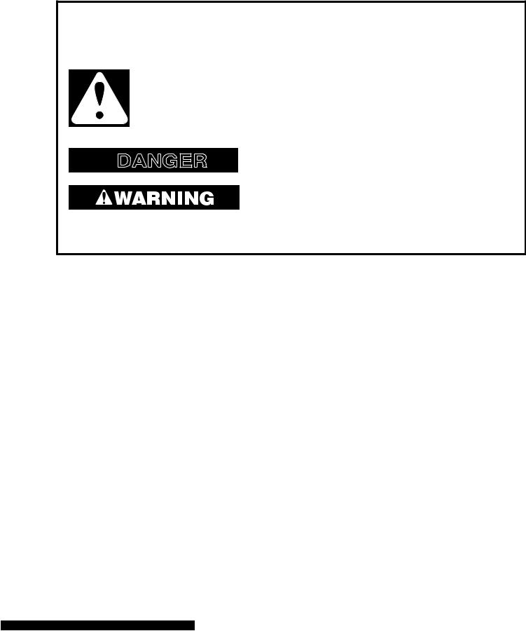
This is the safety alert symbol.
This symbol alerts you to potential hazards that can kill or hurt you and others.
All safety messages will follow the safety alert symbol and either the word “DANGER” or “WARNING.” These words mean:
 DANGER
You can be killed or seriously injured if you don’t immediately follow instructions.
You can be killed or seriously injured if you don’t follow instructions.
All safety messages will tell you what the potential hazard is, tell you how to reduce the chance of injury, and tell you what can happen if the instructions are not followed.
1-1
MODEL & SERIAL NUMBER DESIGNATIONS
MODEL NUMBER
MODEL NUMBER |
|
W |
|
E |
|
D |
|
8 |
|
3 00 S W 0 |
|
|
|
|
|
|
|||||||
|
|||||||||||
|
|
|
|
|
|
|
|
|
|
|
|
BRAND |
|
|
|
|
|
|
|
|
|
|
|
W = Whirlpool |
|
|
|
|
|
|
|
|
|
|
|
|
|
|
|
|
|
|
|
|
|
|
|
FUEL |
|
|
|
|
|
|
|
|
|
|
|
E = Electric G = Gas |
|
|
|
|
|
|
|
|
|
|
|
|
|
|
|
|
|
|
|
|
|
|
|
PRODUCT |
|
|
|
|
|
|
|
|
|
|
|
D = Dryer |
|
|
|
|
|
|
|
|
|
|
|
|
|
|
|
|
|
|
|
|
|
|
|
SERIES |
|
|
|
|
|
|
|
|
|
|
|
5 |
= Whirlpool Leap |
6 = Oasis |
|
|
|||||||
7 |
= 24˝ Front Load |
8 = Mid Line Front Load |
|
|
|||||||
9 |
= Duet Front Load |
|
|
|
|
|
|
|
|
|
|
PRICE POINT LEVELS (1 - 9)
TRADE PARTNER ID (00 = BRANDED)
YEAR OF INTRODUCTION
S = 2006, T = 2007
COLOR CODE
T = Biscuit
Q = White
W = White With Metallic Accent
R = White With Metallic (Sport Only)
ENGINEERING CHANGE (NUMERIC)
SERIAL NUMBER
SERIAL NUMBER |
|
M |
|
T |
|
09 |
|
62410 |
|
|
|
|
|||||
|
|
|
|
|
|
|
|
|
DIVISION RESPONSIBILITY |
|
|
|
|
|
|
|
|
M = Marion, OH |
|
|
|
|
|
|
|
|
|
|
|
|
|
|
|
|
|
YEAR OF PRODUCTION |
|
|
|
|
|
|
|
|
T = 2006 |
|
|
|
|
|
|
|
|
|
|
|
|
|
|
|
|
|
WEEK OF PRODUCTION |
|
|
|
|
|
|
|
|
09 = 9th Week |
|
|
|
|
|
|
|
|
|
|
|
|
|
|
|
|
|
PRODUCT SEQUENCE NUMBER
1-2

MODEL & SERIAL NUMBER LABEL
AND TECH SHEET LOCATIONS
The Model & Serial Number Label and Tech Sheet locations are shown below.
Model & Serial
Number Label 
Tech Sheet
(Behind Lower Access Panel)
1-3

SPECIFICATIONS
Model Number |
WED8300SW |
WED8500SR |
|
WGD8300SW |
WGD8500SR |
|
|
|
Model Description |
Matching Dryer For |
Matching Dryer For |
|
Front Load Washer |
Front Load Washer |
|
|
|
Color |
White with Gray |
White with Sterling |
|
Accents |
Bright Accents |
|
|
|
Capacity (Cu.Ft. IEC) |
6.7 |
6.7 |
|
|
|
Venting |
4 way |
4 way |
|
|
|
Reversible Door |
Yes |
Yes |
|
|
|
Lint Screen Location |
Front |
Front |
|
|
|
Height |
36.0" |
36.0" |
|
|
|
Install Depth: Min - Max |
28.90" - 32.90" |
28.90" - 32.90" |
|
|
|
Width |
27" |
27" |
Product Weight (approx) |
122 lbs. |
122 lbs. |
|
|
|
1-4
INSTALLATION INFORMATION
INSTALLATION INSTRUCTIONS
TOOLS AND PARTS
Gather the required tools and parts before starting installation. Read and follow the safety instructions provided with any tools listed here.
Electric Models
•Flat-blade screwdriver
•#2 Phillips screwdriver
•Adjustable wrench that opens to 1˝ (2.5 cm) or hex-head socket wrench (for adjusting dryer feet)
•Wire stripper (direct wire installations)
•Level
•Vent clamps
•Caulking gun and compound (for installing new exhaust vent)
•Tin snips (new vent installations)
•1/4˝ nut driver or socket wrench (recommended)
•Tape measure
Gas Models
•8˝ or 10˝ pipe wrench
•8˝ or 10˝ adjustable wrench (for gas connections)
•Flat-blade screwdriver
•Adjustable wrench that opens to 1˝ (2.5 cm) or hex-head socket wrench (for adjusting dryer feet)
•1/4˝ nut driver or socket wrench (recommended)
•Level
•Vent clamps
•Knife
•Pipe-joint compound resistant to LP gas
•Caulking gun and compound (for installing new exhaust vent)
•Pliers
•Tape measure
Parts Supplied
Remove parts packages from dryer drum. Check that all parts are included.
• Parts package
4 Leveling legs
NOTE: Do not use leveling legs if installing the dryer on a pedestal.
Parts needed
Check local codes and with gas supplier. Check existing gas supply, electrical supply and venting. Read “Electrical Requirements,” “Gas Supply Requirements” and “Venting Requirements” before purchasing parts.
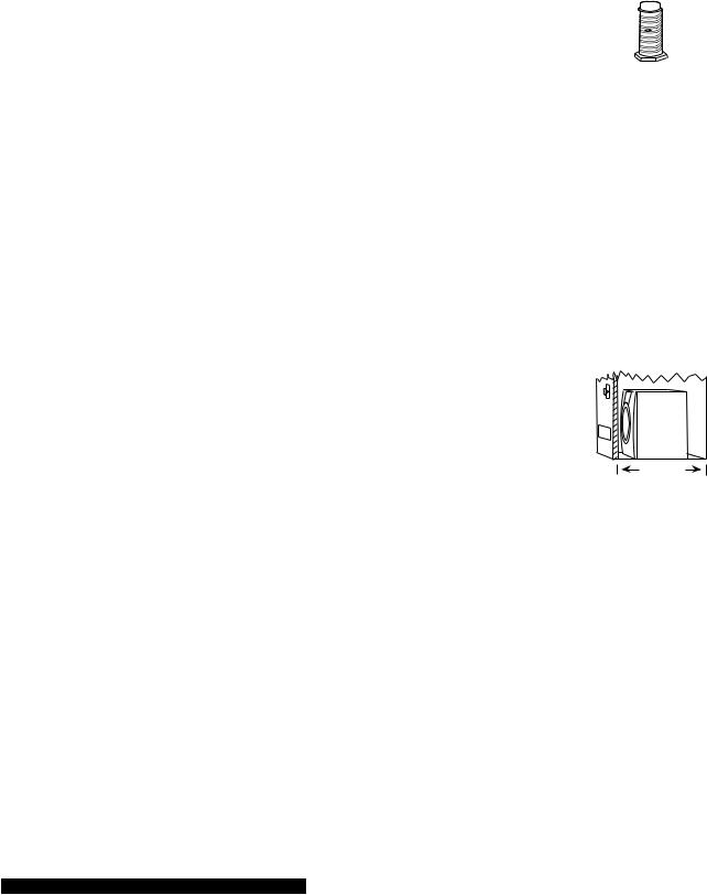
•For close-clearance installations between 28.65˝ (72.77 cm) and 34.15˝ (86.74 cm), see “Plan Vent System” section for venting requirements.
34.15" (86.74 cm)
Mobile home installations require special parts (listed following) that may be ordered by calling the dealer from whom you purchased your dryer. For further information, please refer to the “Assistance or Service” section of the “Use & Care Guide.”
•Mobile Home Installation Kit. Ask for Part Number 346764.
•Metal exhaust system hardware.
2-1
OPTIONS
Pedestal
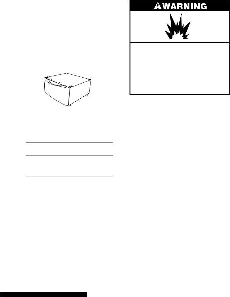
Are you placing the dryer on a pedestal? You have the option of purchasing pedestals of different heights separately for this dryer. You may select a 10˝ (25.4 cm) pedestal or a 15.5˝ (39.4 cm) pedestal with a shelf and bin dividers. These pedestals will add to the total height of the unit for a total height of approximately 46˝ (116.8 cm) or 51.5˝ (130.8 cm).
For a garage installation, you will need to place the dryer at least 18˝ (46 cm) above the floor.
Optional pedestal (15.5˝ [39.4 cm] model shown)
To order, call the dealer from whom you purchasedyourdryerorrefertothe“Assistanceor Service” section of the “Use & Care Guide.”
Pedestal |
Color |
Part Number |
Height |
|
|
10" (25.4 cm) |
White |
WHP1000SQ |
|
|
|
15.5" (39.4 cm) with |
White |
WHP1500SQ |
shelf and bin dividers |
|
|
Drying Rack
To order a drying rack, call the dealer from whom you purchased the dryer or refer to the “Assistance or Service” section of the “Use & Care Guide.” Ask for Part Number 8563738.
Stack Kit
Are you planning to stack your DUETSPORT™ washer and dryer? To do so, you will need to purchase a Stack Kit.
To order, call the dealer from whom you purchased your dryer or refer to the “Assistance or Service” section of the “Use & Care Guide.” Ask for Part Number 8572546.
LOCATION REQUIREMENTS
Explosion Hazard
Keep flammable materials and vapors, such as gasoline, away from dryer.
Place dryer at least 18 inches (46 cm) above the floor for a garage installation.
Failure to do so can result in death, explosion, or fire.
You will need
•Alocation that allows for proper exhaust installation. See “Venting Requirements.”
•Electric Models Only: A separate 30-amp circuit.
•If you are using a power cord, a grounded electrical outlet located within 2 ft (61 cm) of either side of the dryer. See “Electrical Requirements.”
•A sturdy floor to support the total dryer weight of 127 lbs (57.6 kg). The combined weight of a companion appliance should also be considered.
•A level floor with a maximum slope of 1˝(2.5 cm) under entire dryer. (If slope is greater than 1˝ [2.5 cm], install Extended Dryer Feet Kit, Part No. 279810.) Clothes may not tumble properly and automatic sensor cycles may not operate correctly if dryer is not level.
•For a garage installation, you will need to place the dryer at least 18˝ (46 cm) above
the floor. If using a pedestal, you will need 18˝ (46 cm) to the bottom of the dryer.
Do not operate your dryer at temperatures below 45°F (7°C). At lower temperatures, the dryer might not shut off at the end of an automatic cycle. Drying times can be extended.
2-2
The dryer must not be installed or stored in an area where it will be exposed to water and/or weather.
Check code requirements. Some codes limit, or do not permit, installation of the dryer in garages, closets, mobile homes, or sleeping quarters. Contact your local building inspector.
NOTE: No other fuel-burning appliance can be installed in the same closet as a dryer.
Installation Clearances
The location must be large enough to allow the dryer door to open fully.
Dryer Dimensions
50½" (128.27 cm)
36" (91.4 cm)
*28.65" |
|
(72.77 cm) |
27" |
|
|
|
(68.6 cm) |
*Most installations require a minimum 5˝ (12.7 cm) clearance behind the dryer for the exhaust vent with elbow. See “Venting Requirements.”
Installation spacing for recessed area or closet installation
The following spacing dimensions are recommended for this dryer. This dryer has been tested for spacing of 0˝ (0 cm) clearance on the sides and rear. Recommended spacing should be considered for the following reasons:
•Additional spacing should be considered for ease of installation and servicing.
•Additional clearances might be required for wall, door and floor moldings.
•Additional spacing should be considered on all sides of the dryer to reduce noise transfer.
•For closet installation, with a door, minimum ventilation openings in the top and bottom of the door are required. Louvered doors with equivalent ventilation openings are acceptable.
•Companion appliance spacing should also be considered.
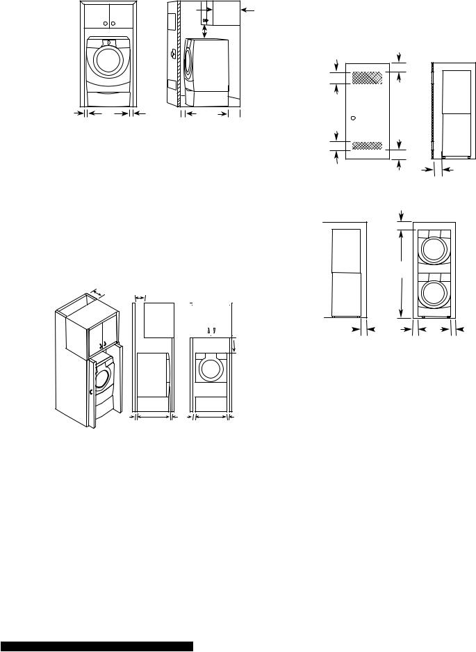
Custom undercounter installation - Dryer only
|
|
2"* |
|
|
(5 cm) |
36" min |
|
|
(91.4 cm) |
|
|
1"* |
27" |
1"* |
(2.5 cm) |
(68.6 cm) |
(2.5 cm) |
* Required Spacing
Closet installation - Dryer only
|
|
|
|
3"* |
|
|
14" max.* |
|
(7.6 cm) |
|
|
(35.6 cm) |
48 in.2* |
|
|
|
|
(310 cm 2) |
|
|
15" min.* |
|
|
|
|
(38.1 cm) |
|
|
|
|
|
|
24 in.2* |
|
|
|
|
(155 cm 2) |
3"* |
|
|
|
|
(7.6 cm) |
1"* |
28.65" |
5"** |
|
|
(2.5 cm) |
(72.77 cm) (12.7 cm) |
|
|
|
A |
|
|
B |
|
A.Side view - closet or confined area
B.Closet door with vents
* Required spacing
**For side or bottom venting, 0˝(0 cm) spacing is allowed.
2-3
Recessed or closet installation - Dryer on pedestal
1" |
27" |
1" |
(2.5 cm) |
(68.6 cm) |
(2.5 cm) |
|
|
14" max.* |
|
|
(35.6 cm) |
|
15" min.* |
|
|
(38.1 cm) |
|
1" |
28.65" |
5"** |
(2.5 cm) |
(72.77 cm) (12.7 cm) |
A B
A.Recessed area
B.Side view - closet or confined area
* Required spacing
**For side or bottom venting, 0˝(0 cm) spacing is allowed.
Installation spacing for cabinet installation
•The dimensions shown are for the recommended spacing.
•For cabinet installation, with a door, minimum ventilation openings in the top of the cabinet are required.
7"* (17.8 cm) |
7"* (17.8 cm) |
 9"*
9"*
(22.9 cm)
5"** |
28.65" |
1" |
1" |
27" |
1" |
(12.7 cm) |
(72.77 cm) (2.5 cm) |
(2.5 cm) (68.6 cm) (2.5 cm) |
|||
* Required spacing
** For side or bottom venting, 0˝(0 cm) spacing is allowed.
Recommended installation spacing for recessed or closet installation with stacked washer and dryer
The dimensions shown are for the recommended spacing
48 in.2 *
(310 cm2)
3"* (7.6 cm)
|
3"* (7.6 cm) |
24 in.2 * |
1"* (2.5 cm) |
(155 cm2) |
|
* Required spacing |
|
|
6"* (15.2 cm) |
72" (182.9 cm)
5"* |
|
|
|
1" |
|
27" |
|
1" |
|
|
|
|
|||||
(12.7 cm) |
|
|
(2.5 cm) |
(68.6 cm) |
|
(2.5 cm) |
||
* Required spacing
Mobilehome-additionalinstallationrequire- ments
This dryer is suitable for mobile home installations. The installation must conform to the Manufactured Home Construction and Safety Standard, Title 24 CFR, Part 3280 (formerly the Federal Standard for Mobile Home Construction and Safety, Title 24, HUD Part 280).
Mobile home installations require:
•Metal exhaust system hardware, which is available for purchase from your dealer.
•Special provisions must be made in mobile homes to introduce outside air into the dryer. The opening (such as a nearby window) should be at least twice as large as the dryer exhaust opening.
2-4

ELECTRICAL REQUIREMENTS Electric Models Only
It is your responsibility
•To contact a qualified electrical installer.
•To be sure that the electrical connection is adequate and in conformance with the National Electrical Code, ANSI/NFPA 70latest edition and all local codes and ordinances.
The National Electric Code requires a 4-wire supply connection for homes built after 1996, dryer circuits involved in remodeling after 1996, and all mobile home installations.
Acopy of the above code standards can be obtained from: National Fire Protection Association, One Batterymarch Park, Quincy, MA 02269.
•To supply the required 3 or 4 wire, single phase, 120/240 volt, 60-Hz., AC-only electrical supply (or 3 or 4 wire, 120/208 volt electrical supply, if specified on the serial/ rating plate) on a separate 30-amp circuit, fused on both sides of the line. A time-de- lay fuse or circuit breaker is recommended. Connect to an individual branch circuit. Do not have a fuse in the neutral or grounding circuit.
•Do not use an extension cord.
•If codes permit and a separate ground wire is used, it is recommended that a qualified electrician determine that the ground path is adequate.
Electrical Connection
To properly install your dryer, you must determine the type of electrical connection you will be using and follow the instructions provided for it here.
•If local codes do not permit the connection of a neutral ground wire to the neutral wire, see “Optional 3-wire connection” section.
•This dryer is manufactured ready to install with a 3-wire electrical supply connection. The neutral ground wire is permanently connected to the neutral conductor (white wire) within the dryer. If the dryer is installed with a 4-wire electrical supply connection, the neutral ground wire must be removed from the external ground conductor screw (green screw), and secured under the neutral terminal (center or white wire) of the terminal block. When the neutral ground wire is secured under the neutral terminal (center or white wire) of the terminal block, the dryer cabinet is isolated from the neutral conductor.
•A 4-wire power supply connection must be used when the appliance is installed in a location where grounding through the neutral conductor is prohibited. Grounding through the neutral is prohibited for (1) new branchcircuit installations,(2) mobile homes, (3) recreational vehicles, and (4) areas where local codes prohibit grounding through the neutral conductors.
If using a power supply cord:
Use a UL listed power supply cord kit marked for use with clothes dryers. The kit should contain:
•A UL listed 30-amp power supply cord, rated 120/240-volt minimum. The cord should be type SRD or SRDT and be at least 4 ft (1.22 m) long. The wires that connect to the dryer must end in ring terminals or spade terminals with upturned ends.
•A UL listed strain relief.
2-5
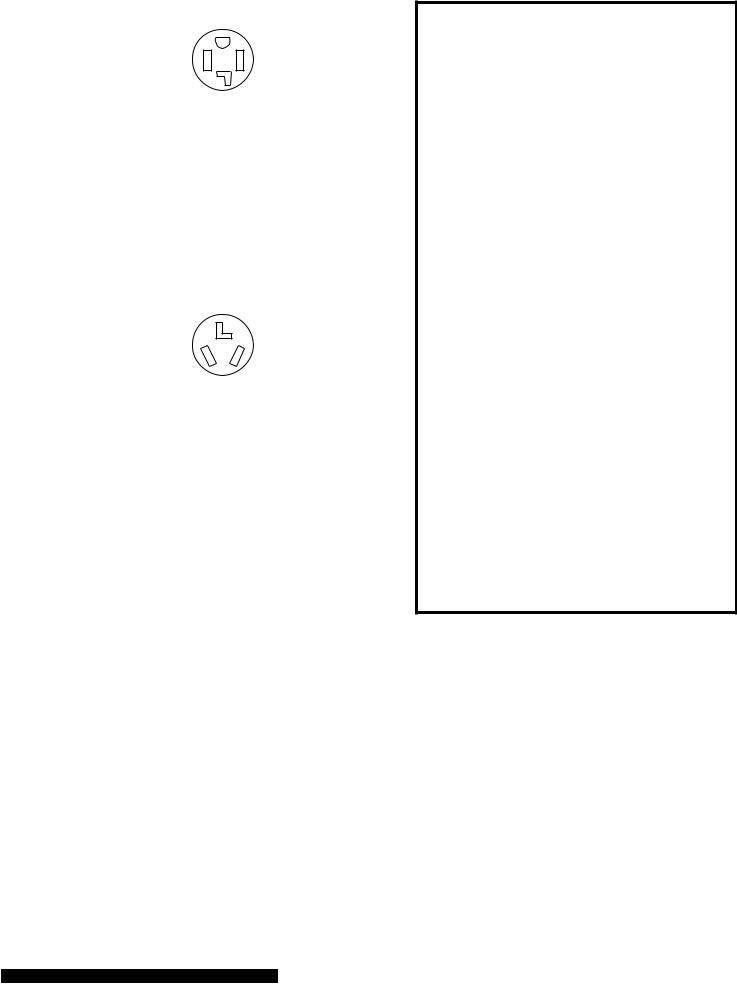
If your outlet looks like this:
4-wire receptacle (14-30R)
Then choose a 4-wire power supply cord with ring or spade terminals and UL listed strain relief. The 4-wire power supply cord, at least 4 ft (1.22 m) long, must have 4, 10-gauge copper wires and match a 4-wire receptacle of NEMAType 14-30R. The ground wire (ground conductor) may be either green or bare. The neutral conductor must be identified by a white cover.
If your outlet looks like this:
3-wire receptacle (10-30R)
Then choose a 3-wire power supply cord with ring or spade terminals and UL listed strain relief. The 3-wire power supply cord, at least 4 ft (1.22 m) long, must have 3, 10-gauge copper wires and match a 3-wire receptacle of NEMA Type 10-30R.
If connecting by direct wire:
Power supply cable must match power supply (4-wire or 3-wire) and be:
•Flexible armored cable or nonmetallic sheathed copper cable (with ground wire), protected with flexible metallic conduit. All current-carrying wires must be insulated.
•10-gauge solid copper wire (do not use aluminum).
•At least 5 ft (1.52 m) long.
GROUNDING INSTRUCTIONS
• For a grounded, cord-connected dryer:
This dryer must be grounded. In the event of malfunction or breakdown, grounding will reduce the risk of electric shock by providing a path of least resistance for electric current. This dryer uses a cord having an equipment-grounding conductor and a grounding plug. The plug must be plugged into an appropriate outlet that is properly installed and grounded in accordance with all local codes and ordinances.
• For a permanently connected dryer:
This dryer must be connected to a grounded metal, permanent wiring system, or an equipment-grounding conductor must be run with the circuit conductors and connected to the equipment-grounding terminal or lead on the dryer.
WARNING: Improper connection of the equipment-grounding conductor can result in a risk of electric shock. Check with a qualified electrician or service representative or personnel if you are in doubt as to whether the dryer is properly grounded. Do not modify the plug on the power supply cord: if it will not fit the outlet, have a proper outlet installed by a qualified electrician.
2-6
ELECTRICAL CONNECTION Electric Models Only
POWER SUPPLY CORD
Fire Hazard
Use a new UL listed 30 amp power supply cord.
Use a UL listed strain relief.
Disconnect power before making electrical connections.
Connect neutral wire (white or center wire) to center terminal (silver).
Ground wire (green or bare wire) must be connected to green ground connector.
Connect remaining 2 supply wires to remaining 2 terminals (gold).
Securely tighten all electrical connections.
Failure to do so can result in death, fire, or electrical shock.
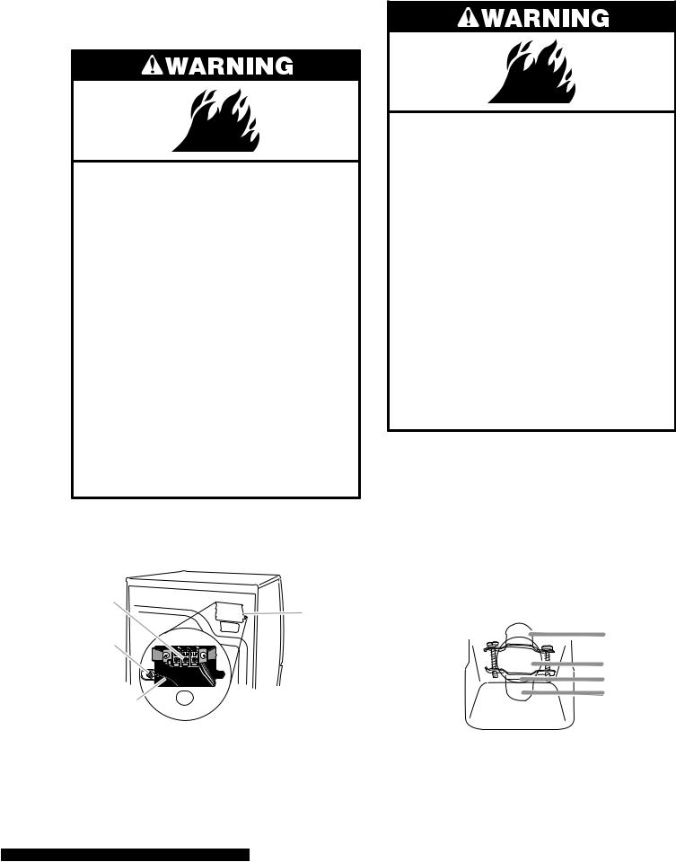
1.Disconnect power.
2.Remove the hold-down screw and terminal block cover.
C
D
B
A
A.Neutral ground wire
B.External ground conductor screw
C.Center, silver-colored terminal block screw
D.Terminal block cover and hold-down screw
DIRECT WIRE
Fire Hazard
Use 10 gauge solid copper wire. Use a UL listed strain relief.
Disconnect power before making electrical connections.
Connect neutral wire (white or center wire) to center terminal (silver).
Ground wire (green or bare wire) must be connected to green ground connector.
Connect remaining 2 supply wires to remaining 2 terminals (gold).
Securely tighten all electrical connections.
Failure to do so can result in death, fire, or electrical shock.
Style 1: Power supply cord strain relief
•Remove the screws from a 3/4˝ (1.9 cm) UL listed strain relief (UL marking on strain relief). Put the tabs of the two clamp sections into the hole below the terminal block opening so that one tab is pointing up and the other is pointing down, and hold in place. Tighten strain relief screws just enough to hold the two clamp sections together.
|
A |
|
B |
|
C |
|
D |
A. Strain relief tab pointing up |
C. Clamp section |
B. Hole below terminal block opening |
D. Strain relief tab pointing down |
3. Install strain relief.
2-7
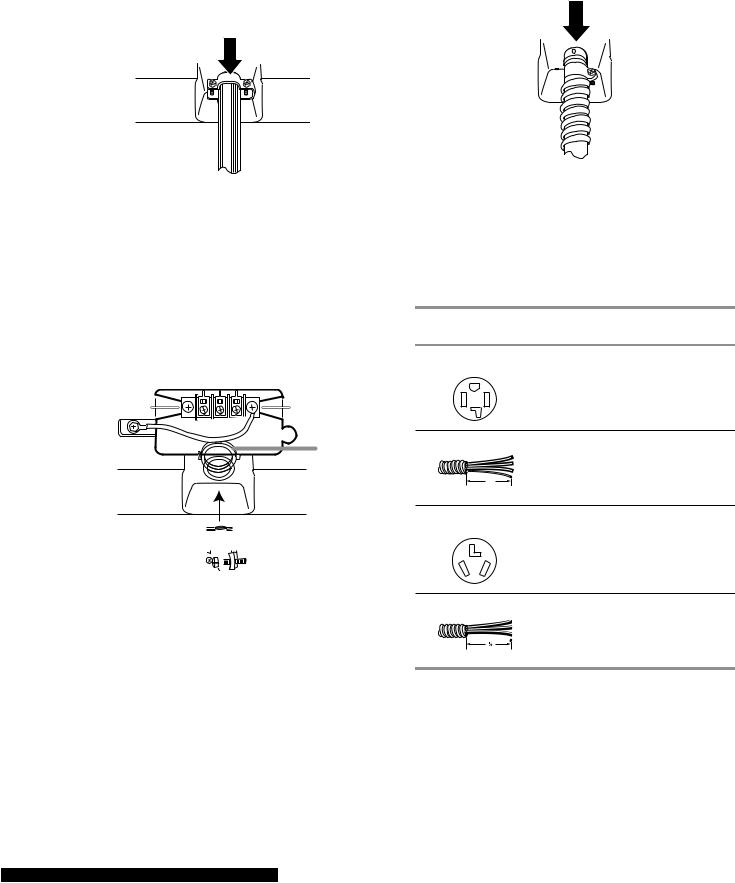
•Put power supply cord through the strain relief. Be sure that the wire insulation on the power supply cord is inside the strain relief. The strain relief should have a tight fit with the dryer cabinet and be in a horizontal position. Do not further tighten strain relief screws at this point.
Style 2: Direct wire strain relief
•Unscrew the removable conduit connector and any screws from a 3/4˝ (1.9 cm) UL listed strain relief (UL marking on strain relief). Put the threaded section of the strain relief through the hole below the terminal block opening. Reaching inside the terminal block opening, screw the removable conduit connector onto the strain relief threads.
 A
A
 B
B
 C
C
A.Removable conduit connector
B.Hole below terminal block opening
C.Strain relief threads
•Put direct wire cable through the strain relief. The strain relief should have a tight fit with the dryer cabinet and be in a horizontal position. Tighten strain relief screw against the direct wire cable.
4.Now complete installation following instructions for your type of electrical connection:
4-wire (recommended)
3-wire (if 4-wire is not available)
Electrical Connection Options
If your home has: |
And you will be |
Go to Section |
|
connecting to: |
|
4-wire receptacle |
A UL listed, |
4-wire connection: |
(NEMA Type 14-30R) |
120/240-volt |
Power supply cord |
|
minimum, |
|
|
30-amp, dryer |
|
|
power supply |
|
|
cord* |
|
4-wire direct |
A fused |
4-wire connection: |
|
disconnect or |
Direct Wire |
|
circuit breaker |
|
5" |
box* |
|
|
|
|
(12.7 cm) |
|
|
3-wire receptacle |
A UL listed, |
3-wire connection: |
(NEMA type 10-30R) |
120/240-volt |
Power supply cord |
|
minimum, |
|
|
30-amp, dryer |
|
|
power supply |
|
|
cord* |
|
3-wire direct |
A fused |
3-wire connection: |
|
disconnect or |
Direct Wire |
|
circuit breaker |
|
3 " |
box* |
|
|
|
|
(8.9 cm) |
|
|
*If local codes do not permit the connection of a cabinet-ground conductor to the neutral wire, go to “Optional 3-wire connection” section.
2-8
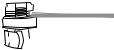
4-wire connection: Power supply cord
IMPORTANT: A 4-wire connection is required for mobile homes and where local codes do not permit the use of 3-wire connections.
A |
B |
|
F |
|
|
|
|
|
C D |
E |
G |
A.4-wire receptacle (NEMA type 14-30R)
B.4-prong plug
C.Ground prong
D.Neutral prong
E.Spade terminals with upturned ends
F. ¾" (1.9 cm) UL listed strain relief
G.Ring terminals
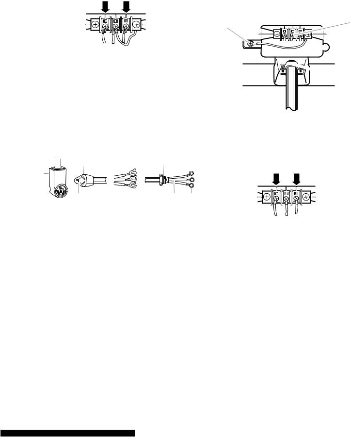
1.Remove center silver-colored terminal block screw.
2.Remove neutral ground wire from external ground conductor screw. Connect neutral ground wire and the neutral wire (white or center wire) of power supply cord under center, silver-colored terminal block screw. Tighten screw.
A
C
3.Connect ground wire (green or bare) of power supply cord to external ground conductor screw. Tighten screw.
A |
D |
B |
E |
|
|
C |
F |
|
A.External ground conductor screw
B.Ground wire (green or bare) of power supply cord
C.³⁄4 " (1.9 cm) UL listed strain relief
D.Center silver-colored terminal block screw
E.Neutral ground wire
F. Neutral wire (white or center wire)
4.Connect the other wires to outer terminal block screws. Tighten screws.
B |
D |
|
|
|
E |
A.External ground conductor screw - Dotted line shows position of NEUTRAL ground wire before being moved to center silver-colored terminal block screw
B.Center silver-colored terminal block screw
C.Neutral ground wire
D.Neutral wire (white or center wire)
E.¾" (1.9 cm) UL listed strain relief
5.Tighten strain relief screws.
6.Insert tab of terminal block cover into slot of dryer rear panel. Secure cover with hold-down screw.
7.You have completed your electrical connection. Now go to “Venting Requirements.”
2-9
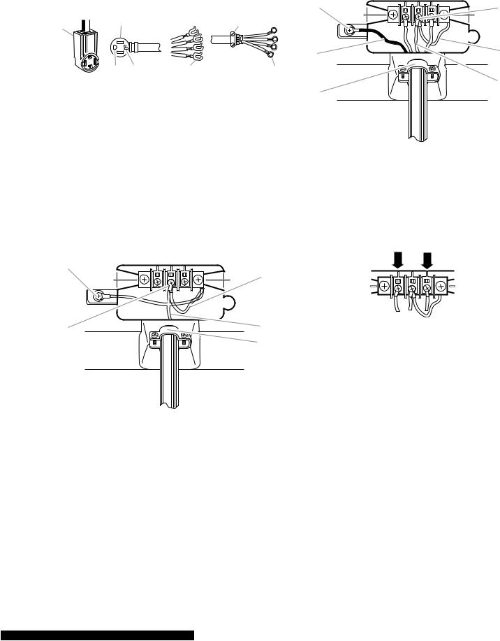
4-wire connection: Direct wire
IMPORTANT: A 4-wire connection is required for mobile homes and where local codes do not permit the use of 3-wire connections.
Direct wire cable must have 5 ft (1.52 m) of extra length so dryer can be moved if needed.
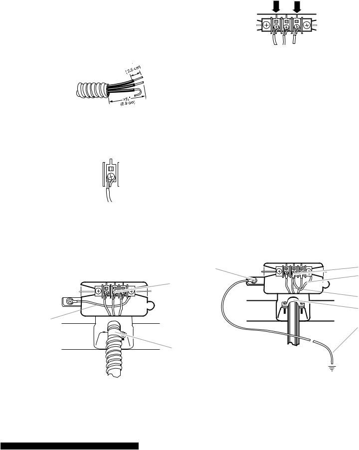
Strip 5˝ (12.7 cm) of outer covering from end of cable, leaving bare ground wire at 5˝ (12.7 cm). Cut 1-1/2˝ (3.8 cm) from 3 remaining wires. Strip insulation back 1˝(2.5 cm). Shape ends of wires into a hook shape.
When connecting to the terminal block, place the hooked end of the wire under the screw of the terminal block (hook facing right), squeeze hooked end together and tighten screw, as shown.
1.Remove center silver-colored terminal block screw (see top right illustration).
2.Remove neutral ground wire from external ground conductor screw. Connect neutral ground wire and place the hooked end (hook facing right) of the neutral wire (white or center wire) of direct wire cable under the center screw of the terminal block. Squeeze hooked ends together. Tighten screw. (See top right illustration.)
B
A
C
 D
D
E
A.External ground conductor screw - Dotted line shows position of NEUTRAL ground wire before being moved to center silver-colored terminal block screw
B.Center silver-colored terminal block screw
C.Neutral ground wire
D.Neutral wire (white or center wire)
E.¾" (1.9 cm) UL listed strain relief
3.Connect ground wire (green or bare) of direct wire cable to external ground conductor screw. Tighten screw.
A |
D |
|
|
|
E |
B |
|
|
F |
C |
|
A.External ground conductor screw
B.Ground wire (green or bare) of power supply cable
C.¾" (1.9 cm) UL listed strain relief
D.Center silver-colored terminal block screw
E.Neutral ground wire
F. Neutral wire (white or center wire)
2-10
4.Place the hooked ends of the other direct wire cable wires under the outer terminal block screws (hooks facing right). Squeeze hooked ends together. Tighten screws.
5.Tighten strain relief screw.
6.Insert tab of terminal block cover into slot of dryer rear panel. Secure cover with hold-down screw.
7.You have completed your electrical connection. Now go to “Venting Requirements.”
3-wire connection: Power supply cord
Use where local codes permit connecting cabinet-ground conductor to neutral wire.
 B D E A


C G F
A.3-wire receptacle (NEMA type 10-30R)
B.3-wire plug
C.Neutral prong
D.Spade terminals with up turned ends
E.³⁄4 " (1.9 cm) UL listed strain relief
F. Ring terminals
G. Neutral (white or center wire)
1.Loosen or remove center silver-colored terminal block screw.
2.Connect neutral wire (white or center wire) of power supply cord to the center, silvercolored terminal screw of the terminal block. Tighten screw.
C
A
B 

 D
D
 E
E
A.External ground conductor screw
B.Neutral ground wire
C.Center silver-colored terminal block screw
D.Neutral wire (white or center wire)
E.³⁄4 " (1.9 cm) UL listed strain relief
3.Connect the other wires to outer terminal block screws. Tighten screws.
4.Tighten strain relief screws.
5.Insert tab of terminal block cover into slot of dryer rear panel. Secure cover with hold-down screw.
6.You have completed your electrical connection. Now go to “Venting Requirements.”
2-11
3-wire connection: Direct wire
Use where local codes permit connecting cabinet-ground conductor to neutral wire.
Direct wire cable must have 5 ft (1.52 m) of extra length so dryer can be moved if needed.
Strip 3-1/2˝ (8.9 cm) of outer covering from end of cable. Strip insulation back 1˝ (2.5 cm). If using 3-wire cable with ground wire, cut bare wire even with outer covering. Shape ends of wires into a hook shape.
1
When connecting to the terminal block, place the hooked end of the wire under the screw of the terminal block (hook facing right), squeeze hooked end together and tighten screw, as shown.
1.Loosen or remove center silver-colored terminal block screw.
2.Place the hooked end of the neutral wire (white or center wire) of direct wire cable under the center screw of terminal block (hook facing right). Squeeze hooked end together. Tighten screw.
C
A 
B 
 D
D
E
A.External ground conductor screw
B.Neutral ground wire
C.Center silver-colored terminal block screw
D.Neutral wire (white or center wire)
E.³⁄4 " (1.9 cm) UL listed strain relief
3.Place the hooked ends of the other direct wire cable wires under the outer terminal block screws (hooks facing right). Squeeze hooked ends together. Tighten screws.
4.Tighten strain relief screw.
5.Insert tab of terminal block cover into slot of dryer rear panel. Secure cover with hold-down screw.
6.You have completed your electrical connection. Now go to “Venting Requirements.”
Optional 3-wire connection
Use for direct wire or power supply cord where local codes do not permit connecting cabinet-ground conductor to neutral wire.
1.Remove center silver-colored terminal block screw.
2.Remove neutral ground wire from external ground conductor screw. Connect neutral ground wire and the neutral wire (white or center wire) of power supply cord/cable under center, silver-colored terminal block screw. Tighten screw.
A |
B |
|
C |
 D
D
E
F
A.External ground conductor screw
B.Center silver-colored terminal block
C.Neutral ground wire
D.Neutral wire (white or center wire)
E.³⁄4 " (1.9 cm) UL listed strain relief
F. Grounding path determined by a qualified electrician
2-12
3.Connect the other wires to outer terminal block screws. Tighten screws.
4.Tighten strain relief screws.
5.Insert tab of terminal block cover into slot of dryer rear panel. Secure cover with hold-down screw.
6.Connect a separate copper ground wire from the external ground conductor screw to an adequate ground.
7.You have completed your electrical connection. Now go to “Venting Requirements.”
ELECTRICAL REQUIREMENTS
Gas Models Only
Electrical Shock Hazard Plug into a grounded 3 prong outlet. Do not remove ground prong.
Do not use an adapter.
Do not use an extension cord.
Failure to follow these instructions can result in death, fire, or electrical shock.
•120 Volt, 60 Hz., AC only, 15or 20-amp fused electrical supply is required. A timedelay fuse or circuit breaker is recommended. It is also recommended that a separate circuit serving only this dryer be provided.
GROUNDING INSTRUCTIONS
• For a grounded, cord-connected dryer:
This dryer must be grounded. In the event of malfunction or breakdown, grounding will reduce the risk of electric shock by providing a path of least resistance for electric current.This dryer is equipped with a cord having an equipment-grounding conductor and a grounding plug. The plug must be plugged into an appropriate outlet that is properly installed and grounded in accordance with all local codes and ordinances.
WARNING: Improper connection of the equipment-grounding conductor can result in a risk of electric shock. Check with a qualified electrician or service representative or personnel if you are in doubt as to whether the dryer is properly grounded. Do not modify the plug provided with the dryer: if it will not fit the outlet, have a proper outlet installed by a qualified electrician.
GAS SUPPLY REQUIREMENTS
Explosion Hazard
Use a new CSA International approved gas supply line.
Install a shut-off valve.
Securely tighten all gas connections.
If connected to LP, have a qualified person make sure gas pressure does not exceed 13˝ (33 cm) water column.
Examples of a qualified person include:
licensed heating personnel, authorized gas company personnel, and authorized service personnel.
Failure to do so can result in death, explosion, or fire.
2-13
Gas Type Natural gas:
This dryer is equipped for use with Natural gas. It is design-certified by CSA International for LP (propane or butane) gases with appropriate conversion.
This dryer must have the correct burner for the type of gas in your home. Burner information is located on the rating plate in the door well of your dryer. If this information does not agree with the type of gas available, contact your dealer or call the phone numbers referenced in the “Assistance or Service” section of the “Use & Care Guide.”
LP gas conversion:
Conversion must be made by a qualified technician.
No attempt shall be made to convert the appliance from the gas specified on the model/ serial rating plate for use with a different gas without consulting the gas company.
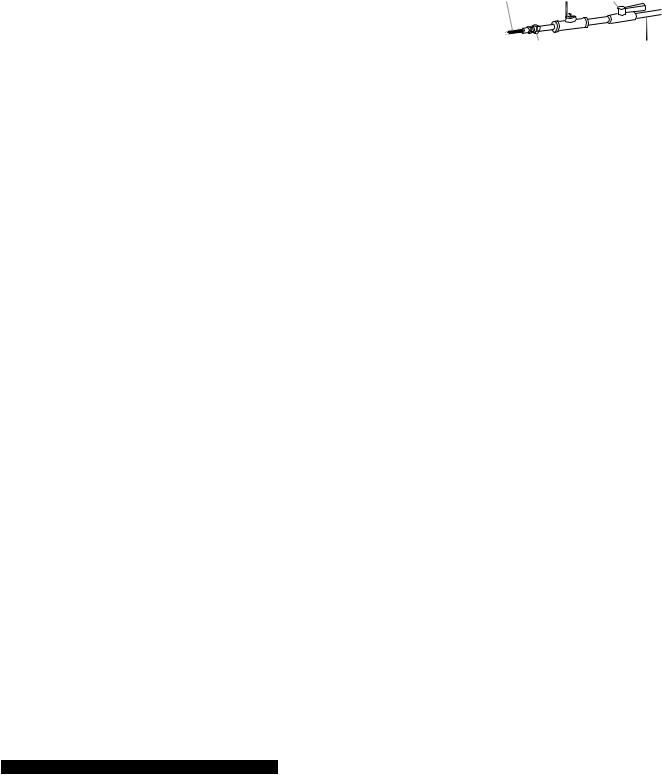
Gas supply line
•1/2˝ IPS pipe is recommended.
•3/8˝ approved tubing is acceptable for lengths under 20 ft (6.1 m) if local codes and gas supplier permit.
•Must include 1/8˝ NPT minimum plugged tapping accessible for test gauge connection, immediately upstream of the gas connection to the dryer (see illustration in the right column).
•Must include a shutoff valve:
In the U.S.A.:
An individual manual shutoff valve must be installed within six (6) feet (1.8 m) of the dryer in accordance with the National Fuel Gas Code, ANSI Z223.1.
In Canada:
An individual manual shutoff valve must be installed in accordance with the B149.1, Natural Gas and Propane Installation Code. It is recommended that an individual manual shutoff valve be installed within six
(6) feet (1.8 m) of the dryer.
The location should be easy to reach for opening and closing.
A C E
B D
A.³⁄8" flexible gas connector
B.³⁄8" pipe to flare adapter fitting
C.1⁄8 " NPT minimum plugged tapping
D.½" NPT gas supply line
E.Gas shutoff valve
Gas supply connection requirements
•For close clearances, a 3/8˝ to 3/8˝ elbow is recommended to avoid kinking of the gas line.
•Use only pipe-joint compound. Do not use TEFLON†® tape.
There are many methods by which your gas dryer can be connected to the gas supply. Listed here are some guidelines for two different methods of connection.
Option 1 (Recommended method)
Flexible stainless steel gas connector:
•If local codes permit, use a new flexible stainless steel gas connector (Design Certified by CSA International) to connect the
dryer to the rigid gas supply line. Use an elbow and a 3/8˝flare x 3/8˝ NPT adapter fitting between the stainless steel gas connector and the dryer gas pipe, as needed to avoid kinking.
†® TEFLON is a registered trademark of E.I. Du Pont De Nemours and Company.
2-14
Option 2 (Alternate method)
Approved aluminum or copper tubing:
•Lengths under 20 ft (6.1 m) can use 3/8˝ approved tubing (if codes and gas supplier permit).
•If you are using Natural gas, do not use copper tubing.
•3/8˝ flare x 3/8˝ NPT adapter fitting between dryer pipe and 3/8˝ approved tubing.
•Lengths over 20 ft (6.1 m) should use larger tubing and a different size adapter fitting.
•If the dryer has been converted to use LP gas, 3/8˝ LP compatible copper tubing can be used. If the total length of the supply line is more than 20 ft (6.1 m), use larger tubing.
NOTE: Pipe-joint compounds that resist the action of LP gas must be used. Do not use TEFLON®† tape.
†® TEFLON is a registered trademark of E.I. Du Pont De Nemours and Company.
Burner input requirements Elevations up to 10,000 ft (3,048 m):
•The design of this dryer is certified by CSA International for use at altitudes up to 10,000 ft (3,048 m) above sea level at the Btu rating indicated on the model/serial number plate. Burner input adjustments are not required when the dryer is operated up to this elevation.
Elevations above 10,000 ft (3,048 m):
•When installed above 10,000 ft (3,048 m) a 4% reduction of the burner Btu rating shown on the model/serial number plate is required for each 1,000 ft (305 m) increase in elevation.
Gas supply pressure testing
•The dryer must be disconnected from the gas supply piping system during pressure testing at pressures greater than 1/2 psi.
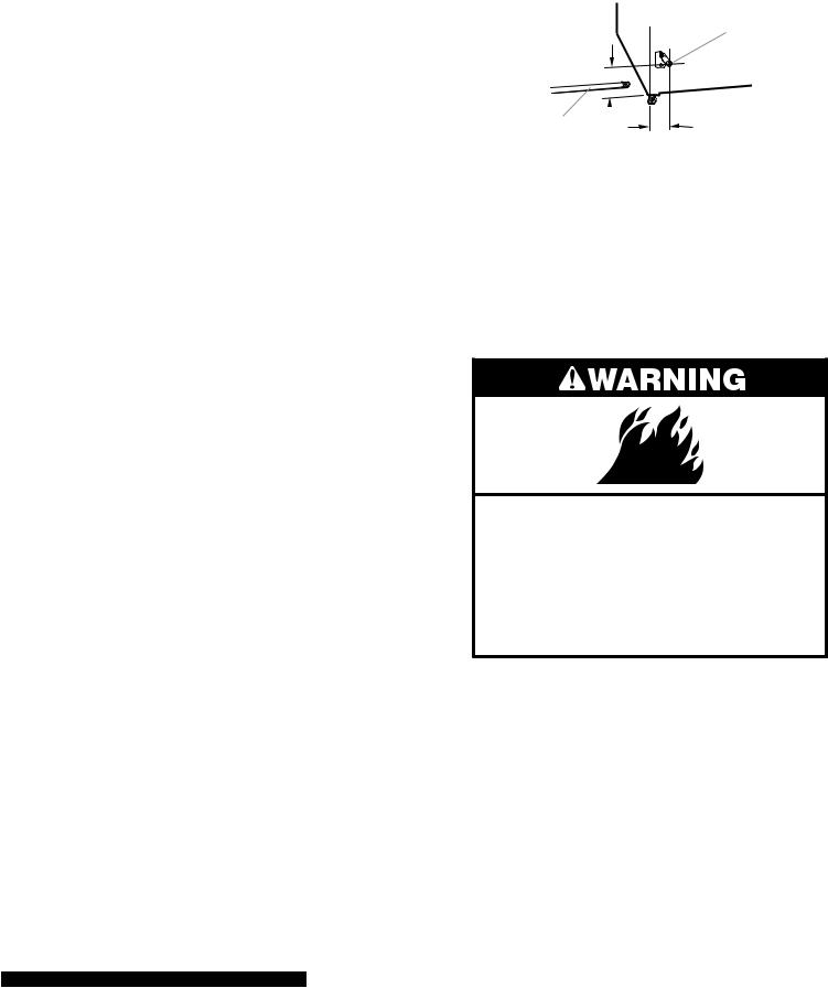
Dryer gas pipe
•The gas pipe that comes out through the rear of your dryer has a 3/8˝ male pipe thread.
B
*6¼" (15.9 cm)
A |
|
1½" |
|
||
|
(3.8 cm) |
A.½" NPT gas supply line
B.³⁄8 " NPT dryer pipe
*NOTE: If the dryer is mounted on a pedestal, the gas pipe height must be an additional 10˝ (25.4 cm) or 15.5˝ (39.4 cm) from the floor, depending on the pedestal model. For a garage installation, the gas pipe height must be an additional 18˝ (46 cm) from the floor.
VENTING REQUIREMENTS
Fire Hazard Use a heavy metal vent. Do not use a plastic vent. Do not use a metal foil vent.
Failure to follow these instructions can result in death or fire.
WARNING: To reduce the risk of fire, this dryer MUST BE EXHAUSTED OUTDOORS.
IMPORTANT: Observe all governing codes and ordinances.
The dryer exhaust must not be connected into any gas vent, chimney, wall, ceiling, or a concealed space of a building.
2-15
If using an existing vent system
•Clean lint from the entire length of the system and make sure exhaust hood is not plugged with lint.
•Replace any plastic or metal foil vent with rigid or flexible heavy metal vent.
•Review Vent system chart. Modify existing vent system if necessary to achieve the best drying performance.
If this is a new vent system
Vent Material
•Use a heavy metal vent. Do not use plastic or metal foil vent.
•4˝ (10.2 cm) heavy metal exhaust vent and clamps must be used. DURASAFE™ venting products are recommended.
4"
10.2 cm
4" (10.2 cm) heavy metal exhaust vent
DURASAFE™ vent products can be purchased from your dealer or by calling Whirlpool Parts and Accessories.
Rigid metal vent
•For best drying performance, rigid metal vents are recommended.
•Rigid metal vent is recommended to prevent crushing and kinking.
Flexible metal vent
•Flexible metal vents are acceptable only if accessible for cleaning.
•Flexible metal vent must be fully extended and supported when the dryer is in its final position.
•Remove excess flexible metal vent to avoid sagging and kinking that may result in reduced airflow and poor performance.
•Do not install flexible metal vent in enclosed walls, ceilings or floors.
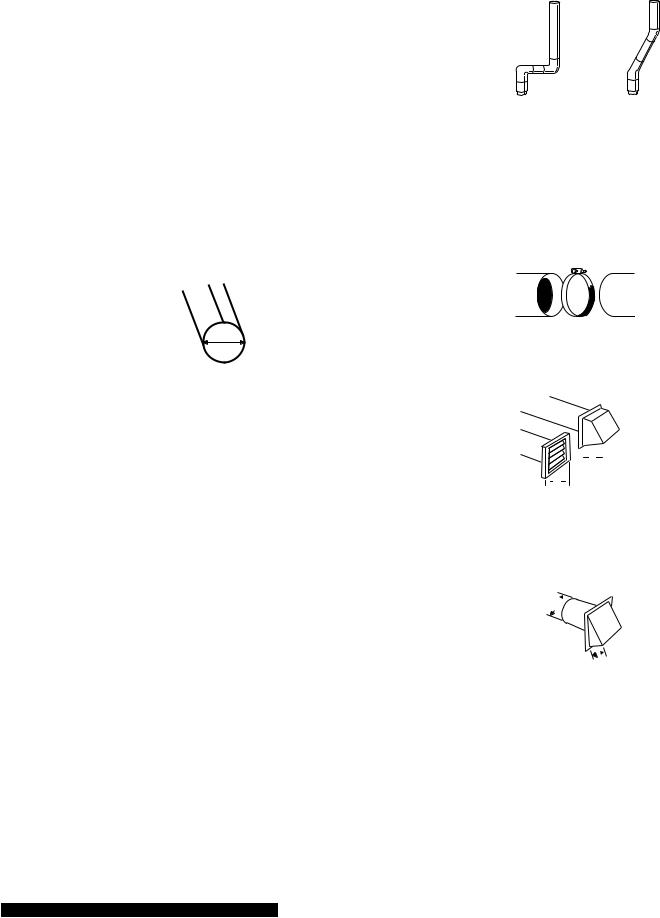
Elbows
45° elbows provide better airflow than 90° elbows
Good |
Better |
Clamps
•Use clamps to seal all joints.
•Exhaust vent must not be connected or secured with screws or other fastening devices that extend into the interior of the duct. Do not use duct tape.
Clamp
Exhaust
Recommended hood styles are shown here.
B
A
 4"
4"  (10.2 cm)
 4"
4" 
(10.2 cm)
A.Louvered hood style
B.Box hood style
The angled hood style (shown here) is acceptable.
4"
(10.2 cm)
 2½" (6.4 cm)
•An exhaust hood should cap the vent to prevent rodents and insects from entering the home.
•Exhaust hood must be at least 12˝(30.5 cm) from the ground or any object that may be in the path of the exhaust (such as flowers, rocks or bushes, snow line, etc.).
2-16
•Do not use an exhaust hood with a magnetic latch.
Improper venting can cause moisture and lint to collect indoors, which may result in:
•Moisture damage to woodwork, furniture, paint, wallpaper, carpets, etc.
•Housecleaning problems and health problems.
PLAN VENT SYSTEM
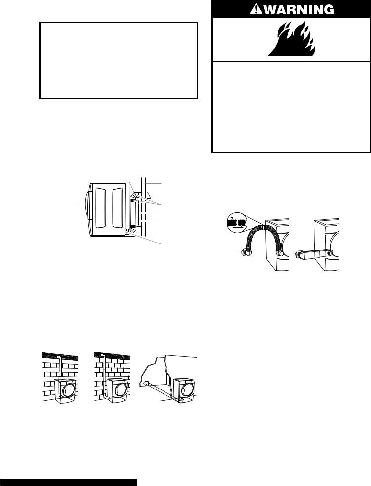
Choose your exhaust installation type Recommended exhaust installations
Typical installations vent the dryer from the rear of the dryer. Other installations are possible.
|
B |
C |
|
|
|
|
|
D |
A |
|
E |
|
|
F |
|
|
G |
A. Dryer |
H |
|
B. Elbow |
||
|
||
C. Wall |
|
|
D. Exhaust hood |
|
|
E. Clamps |
|
|
F. Rigid metal or flexible metal vent |
|
G.Vent length necessary to connect elbows
H.Exhaust outlet
Optional exhaust installations
This dryer can be converted to exhaust out the right side, left side, or through the bottom. Contact your local dealer to have the dryer converted.
Fire Hazard
Cover unused exhaust holes with the following kit:
279818 (white)
Contact your local dealer.
Failure to follow these instructions can result in death, fire, electrical shock, or serious injury.
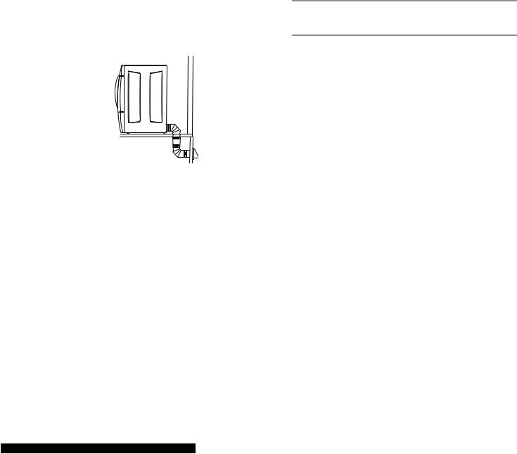
Alternate installations for close clearances
Venting systems come in many varieties. Select the type best for your installation. Two close-clearance installations are shown. Refer to the manufacturer’s instructions.
A B
A.Over-The-Top installation (also available with one offset elbow)
B.Periscope installation
A B C
A.Standard rear offset exhaust installation
B.Left or right side exhaust installation
C.Bottom exhaust installation (not an option with pedestal installations)
2-17
NOTE: The following kits for close clearance alternate installations are available for purchase.
•Over-the-top Installation: Part Number 4396028
•Periscope Installation (For use with dryer
vent to wall vent mismatch):
Part Number 4396037 - 0˝ (0 cm) to 18˝ (45.72 cm) mismatch
Part Number 4396011 - 18˝ (45.72 cm) to 29˝ (73.66 cm) mismatch
Part Number 4396014 - 29˝ (73.66 cm) to 50˝ (127 cm) mismatch
Special provisions for mobile home installations
Theexhaustventmustbesecurely fastenedto a noncombustible portion of the mobile home structure and must not terminate beneath the mobile home. Terminate the exhaust vent outside.
Determine vent path
•Select the route that will provide the straightest and most direct path outdoors.
•Plan the installation to use the fewest number of elbows and turns.
•When using elbows or making turns, allow as much room as possible.
•Bend vent gradually to avoid kinking.
•Use the fewest 90° turns possible.
Determine vent length and elbows needed for best drying performance
•Use the following Vent system chart to determine type of vent material and hood combinations acceptable to use.
NOTE: Do not use vent runs longer than those specified in the Vent system chart. Exhaust systems longer than those specified will:
•Shorten the life of the dryer.
•Reduce performance, resulting in longer drying times and increased energy usage.
The Vent system chart provides venting requirements that will help to achieve the best drying performance.
Vent System Chart
NOTE: Side and bottom exhaust installations have a 90° turn inside the dryer. To determine maximum exhaust length, add one 90° turn to the chart.
Number of |
Type of |
Box or |
Angled |
90º turns |
vent |
louvered |
hoods |
or elbows |
|
hoods |
|
0 |
Rigid metal |
64 ft (20 m) |
58 ft (17.7 m) |
|
Flexible metal |
36 ft (11 m) |
28 ft (8.5 m) |
|
|
|
|
1 |
Rigid metal |
54 ft (16.5 m) |
48 ft (14.6 m) |
|
Flexible metal |
31 ft (9.4 m) |
23 ft (7 m) |
|
|
|
|
2 |
Rigid metal |
44 ft (13.4 m) |
38 ft (11.6 m) |
|
Flexible metal |
27 ft (8.2 m) |
19 ft (5.8 m) |
|
|
|
|
3 |
Rigid metal |
35 ft (10.7 m) |
29 ft (8.8 m) |
|
Flexible metal |
25 ft (7.6 m) |
17 ft (5.2 m) |
|
|
|
|
4 |
Rigid metal |
27 ft (8.2 m) |
21 ft (6.4 m) |
|
Flexible metal |
23 ft (7 m) |
15 ft (4.6 m) |
|
|
|
|
INSTALL VENT SYSTEM
1.Install exhaust hood. Use caulking compound to seal exterior wall opening around exhaust hood.
2.Connect vent to exhaust hood. Vent must
fit inside exhaust hood. Secure vent to exhaust hood with 4˝ (10.2 cm) clamp.
3.Runventtodryerlocation.Usethestraightest path possible. See “Determine vent path.” Avoid 90º turns. Use clamps to seal all joints. Do not use duct tape, screws or other fastening devices that extend into the interior of the vent to secure vent.
2-18
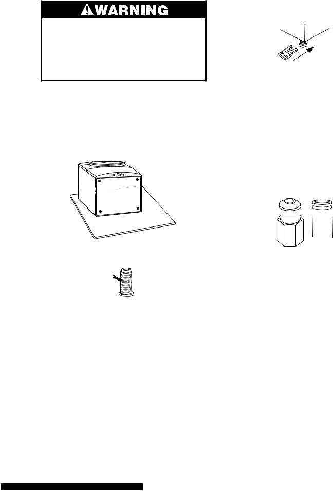
INSTALL LEVELING LEGS
Excessive Weight Hazard
Use two or more people to move and install dryer.
Failure to do so can result in back or other injury.
1.To protect the floor, use a large flat piece of cardboard from the dryer carton. Place cardboard under the entire back edge of the dryer.
2.Firmly grasp the body of the dryer. Gently lay the dryer on the cardboard. See illustration.
3.Examine the leveling legs. Find the diamond marking.
4.Screw the legs into the leg holes by hand. Use a wrench to finish turning the legs until the diamond marking is no longer visible.
5.Place a carton corner post from dryer packaging under each of the 2 dryer back corners. Stand the dryer up. Slide the dryer on the corner posts until it is close to its final location. Leave enough room to connect the exhaust vent.
For mobile home use
Gas dryers must be securely fastened to the floor at the time of installation.
Mobile home installations require a Mobile Home Installation Kit. For more information, please reference the service numbers in the “Assistance or Service” section of the “Use & Care Guide.”
MAKE GAS CONNECTION
1.Remove the red cap from the gas pipe.
2.Using a wrench to tighten, connect the gas supply to the dryer. Use pipe-joint compound on the threads of all nonflared male fittings. If flexible metal tubing is used, be sure there are no kinks.
A

 B
B
A.Flared male fitting
B.Non-flared male fitting
NOTE: For LP gas connections, you must use pipe-joint compound resistant to the action of LP gas. Do not use TEFLON®† tape.
†® TEFLON is a registered trademark of E.I. Du Pont De Nemours and Company.
2-19
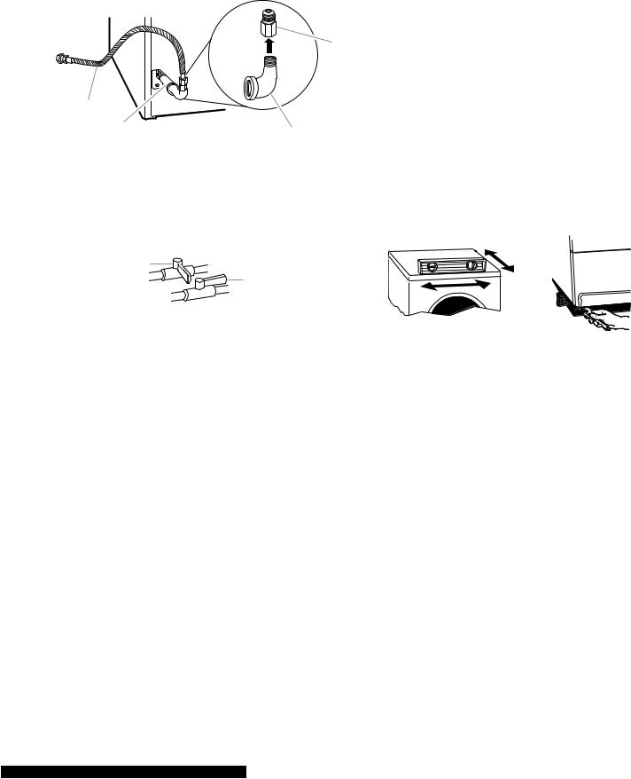
A combination of pipe fittings must be used to connect the dryer to the existing gas line. Shown is a recommended connection. Your connection may be different, according to the supply line type, size and location.
D
A
B C
A.³⁄8 " flexible gas connector
B.³⁄8 " dryer pipe
C.³⁄8 " to ³⁄8 " pipe elbow
D.³⁄8 " pipe-to-flare adapter fitting
3.Open the shutoff valve in the supply line. The valve is open when the handle is parallel to the gas pipe.
A
B
A.Closed valve
B.Open valve
4.Test all connections by brushing on an approved noncorrosive leak-detection solution. Bubbles will show a leak. Correct any leak found.
CONNECT VENT
1.Using a 4˝ (10.2 cm) clamp, connect vent to exhaust outlet in dryer. If connecting to existing vent, make sure the vent is clean. The dryer vent must fit over the dryer exhaust outlet and inside the exhaust hood.
Make sure the vent is secured to exhaust hood with a 4˝ (10.2 cm) clamp.
2.Move dryer into its final position. Do not crush or kink vent.
3.(On gas models) Check that there are no kinks in the flexible gas line.
4.Once exhaust vent connection is made, remove corner posts and cardboard.
LEVEL DRYER
Check the levelness of the dryer. Check levelness first side to side, then front to back.
If the dryer is not level, prop up the dryer using a wood block. Use a wrench to adjust the legs up or down and check again for levelness.
REVERSE DOOR SWING
You can change your door swing from a rightside opening to a left-side opening, if desired.
1.Place a towel or soft cloth on top of the dryer or work space to protect the surface.
2-20

Remove the door assembly
1.Remove the 4 screws that hold the door hinge on the front panel of the dryer.
A 
 B
B
A.Dryer front panel
B.Door assembly
2.Lay the door assembly on a flat, protected surface with the inside (inner door assembly) facing up.
3.Remove the 6 Phillips head screws to release the outer door assembly from the inner door assembly, as indicated below. See illustration. It is important that you remove only the 6 indicated screws.
6.Turn inner ring 180° and lock tabs into place.
Reverse hinge
1.Use a small flat-blade screwdriver to remove 2 plug strips from the inner door. Slide the head of the screwdriver under the plugs, being certain not to scratch the inner door surface. Lift up.
2. Remove hinge cover.
 B
B
C
A 

A. Door hinge
B. Plug strips
C. Hinge cover
3. Remove the 4 screws that attach to the inner door hinge and move the hinge to the other side. Reinstall the 4 screws.
4. Lift the inner door assembly off the outer door assembly.
5. Disengage locking tabs by rotating inner ring clockwise. See illustration.
B A
A. Door hinge
A
A.Inner ring
B.Outer ring
2-21
 Loading...