


Whirlpool AWA 831, AWA 9000, AWA 852, EVIDENCE 7033, WAT 5242 ED QUICK REFERENCE GUIDE
...QUICK REFERENCE GUIDE |
|
GB |
|
|
|
BEFORE USING THE APPLIANCE FOR THE FIRST TIME:
•IMPORTANT: MAKE SURE YOU HAVE READ THE INSTALLATION INSTRUCTIONS.
•IMPORTANT: REMOVE THE TRANSPORT SCREWS AND THE TRANSPORT BRACKET.
•First wash cycle without laundry:
1.Open the tap(s).
2.Close the drum flaps.
3.Pour a small amount of detergent (about 30 ml) into the detergent dispenser compartment  .
.
4.Close the lid.
5.Select a short wash programme and a low spin speed (see programme chart).
6.Switch on the appliance.
This will remove any water remaining in the machine from the manufacturer’s test run.
NORMAL DAILY USE:
1.Open the tap(s).
2.Sort the laundry according to fabric type and colour and load the machine.
3.Close the drum flaps.
4.Add detergent and any additives required into the dispenser.
5.Close the lid.
6.Select the programme, temperature, spin speed and special options.
7.Switch on the appliance.
Read these user instructions carefully to learn about all the functions of your washing machine.
17
GB |
|
|
CONTENTS |
|
|
|
|
|
|
INSTALLATION INSTRUCTIONS |
PAGE 19 |
|||
|
|
|
|
|
WASHING MACHINE AND ACCESSORIES |
PAGE 22 |
|||
|
|
|
|
|
PROTECTING THE ENVIRONMENT |
PAGE 23 |
|||
|
|
|
|
|
SAFETY INSTRUCTIONS |
|
PAGE 23 |
||
|
|
|
|
|
TRANSPORT / HANDLING |
PAGE 23 |
|||
|
|
|
|
|
PREPARING THE WASH |
|
PAGE 24 |
||
|
|
|
|
|
DETERGENT AND ADDITIVES |
PAGE 25 |
|||
|
|
|
|
|
DYEING AND BLEACHING |
PAGE 25 |
|||
|
|
|
|
|
STARCHING |
|
PAGE 25 |
||
|
|
|
|
|
REMOVING THE FOREIGN BODY TRAP |
PAGE 26 |
|||
|
|
|
|
|
DRAINING RESIDUAL WATER |
PAGE 26 |
|||
|
|
|
|
|
MAINTENANCE AND CLEANING |
PAGE 27 |
|||
|
|
|
|
|
TROUBLESHOOTING GUIDE |
PAGE 29 |
|||
|
|
|
|
|
AFTER-SALES SERVICE |
|
PAGE 30 |
||
|
|
|
|
|
18

INSTALLATION INSTRUCTIONS
HOW TO UNPACK THE APPLIANCE
1. Cut and remove the shrink-wrap.
2. Remove the top protection and the protection corners.
3. Remove the bottom protection by tilting and turning the appliance on one rear bottom corner.
4. Open the lid while pressing it slightly down and at the same time operate the handle. Remove the polystyrene cushion.
5. Peel off the light blue protective film from the panel (depending on model).
HOW TO REMOVE THE TRANSPORT SCREWS AND THE TRANSPORT BRACKET
The appliance is fitted with the transport screws and the transport bracket to prevent internal damage while being moved.
Before using the appliance, the transport bracket at the back MUST be removed.
1. Unscrew the two screws A and the four screws B with a flat screwdriver or a N° 8 hex nut screwdriver.
2. Remove the transport bracket.
3. Replace the four outer screws B into the machine again and tighten.
4. Tear off the two stop plugs C from the hose holder and clip them into the openings of the machine D.
Note: In case of future moves, always transport the washing machine upright.
INSTALLATION
• Install the appliance on a solid and level floor surface close to electrical, water and drain connections.
• Make sure that all feet are stable and resting on the floor and then check that the appliance is perfectly level (use a spirit level).
• If the floor is uneven, adjust the levelling feet as required (do not insert pieces of wood, cardboard etc. under the feet).
•The appliance can be installed in a 40 cm width and 63 cm depth space.
Note: It is important to avoid blocking the openings on the underside of the appliance when installing on a carpet floor.
ADJUSTMENT OF THE APPLIANCE
1. To move the appliance into its operating position: Pull the handle situated on the bottom of the front (optional on certain models) a little bit by hand and pull it in the final driving position by foot. Afterwards push the handle back into the original, stable position. The front feet can be adjusted in order to level the appliance.
2.Loosen the locknut using a wrench.
3.Adjust the height of the foot, turning it by hand.
4.Tighten the locknut by turning it anti-clockwise towards the appliance casing.
IMPORTANT: Do not run the appliance while it is standing on the trolleys.
19

INSTALLATION INSTRUCTIONS
WATER SUPPLY
• Water supply: cold water only
• |
Tap: |
3/4” threaded hose connection |
• |
Pressure: |
10-100 N/cm²(1-10 bar). |
Should the appliance be installed in a room which is subject to extremely low temperatures, you need to empty water at the end of each wash programme. Please follow the instructions given in the chapter titled “Draining Residual Water” and disconnect the water inlet hose.
WATER INLET HOSE(S)
1. The mesh filter supplied with the appliance must be inserted in the connection between the supply hose and the tap.
2. Carefully screw the hose connection to the tap preferably by hand. Make sure there are no kinks in the hose and that it is not crushed.
3. Check water-tightness of tap and appliance connections by turning the tap completely on.
• If the hose is too short, replace it with a suitable length of pressure resistant hose (10 bar min., EN 50065 approved type).
• The appliance can be connected without a non-return valve.
• Install the appliance in accordance with regulations of your local water company.
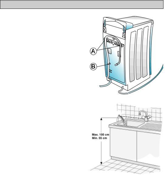
For Great Britain & Ireland only:
Water inlet:
- hot (see A) fill hose;
- and cold (see B) fill hose.
The warm water inlet temperature must not exceed 60° C.
WATER STOP ANTI-FLOODING SYSTEM
(depending on model):
•Screw the threaded connection with the filter into the union nut on the water tap. Open the water tap fully and check the water tightness of the connection point.
•The appliance must not be connected to the mixing tap of a non-pressurized water heater!
•The inlet hose (see arrow C) and the plastic enclosure at the tap connection contain electrical components.
•Do not cut the hose and do not immerse the plastic enclosure in water.
•If the flexible hose is damaged, unplug the appliance from the mains immediately.
If the hose is too short, replace it with a 3 m Water Stop hose (available from After-Sales Service or from your dealer). This operation must be carried out exclusively by a licensed electrician.
C
20
INSTALLATION INSTRUCTIONS
DRAIN HOSE
• Drain hose connection to water outlet.
1. Unhook the drain hose from the right and left hose connection, see A in figure.
Important:
Do NOT loosen the drain hose connection from the clip on the left side, see B in figure, otherwise there is the risk of leakage (danger of scalding with hot water). 2. Fix the “U” bend supplied (inside the drum) to the
free end of the drain hose.
3. Fit the drain hose either to the siphon or hook it over the edge of a sink or bath tub with the “U” bend. Small hand basins are not suitable.
The edge of the tub must be no higher than 100 cm above the floor.
4. If you need to add an extension, use a flexible hose of the same type and secure the unions with screw-on hose clips.
Maximum overall drain hose length: 2.50 m. Maximum drain height (“U” bend): 100 cm. Minimum drain height: 55 cm.
Important:
Make sure there are no kinks in the drain hose and take precautions against it falling while the appliance is running.
ELECTRICAL CONNECTIONS
•Electrical connections must be made in accordance with local regulations.
•The appliance must be connected to the mains exclusively by means of a socket with an earth connection in accordance with established regulations. The appliance must be earthed by law. The manufacturer declines all liability for damage to property or injury to persons or animals deriving either directly or indirectly from failure to observe the above directions.
•The data of voltage, power consumption and the required electrical protection are supplied on the rear of the appliance.
•The electrical power cable must be replaced, if necessary, exclusively by a licensed electrician.
•The appliance conforms to European safety regulations, EC directive 93/68/EEC and standard EN 60555.
•Do not use extension leads or multisockets.
21
 Loading...