

Page 1

SERVICE
Model AVM 683
Version 8538 683 01791 Page
Whirlpool Europe
Customer Services
AVM 683
Service Manual
Microwave oven
AVM 683
Introduction safety 2
Technical data 3 - 11
Spare part list 12
Exploded view 13
Wiring diagram 14
Program diagram 15 - 16
This documentation is only intended for qualified technicians who are aware of the respective safety regulations.
Date: 07.05.1998 Subject to modification
Document-No.: 4812 714 12351
Page 2

07.05.1998 / Page 2 AVM 683 Whirlpool Europe
Doc. No: 4812 714 12351 8538 683 01791 Customer Service
SERVICE
Introduction safety
INTRODUCTION
Before leaving the factory each oven is carefully checked.
It must, however, be installed and used correctly.
Despite all the steps taken to make the oven safe, the safety is dependent on the correct installation and the fact
the user understands how to use and maintain the oven.
The information in this section should be used as a reminder that the oven is safe and that anyone who uses it must
first read the instructions for use in order to be able to use the oven correctly and obtain best results.
SAFETY
To avoid injury to yourself and damage to the appliance always work to the following rules when servicing an oven.
Always disconnect the plug from the mains before starting work.
If there is no plug switch off the electric supply at the control box.
When you have finished servicing an oven before you reconnect it to the mains, make sure that:
- all the internal connections are correct
- the wires are insulated and not touching the door or the cabinet or anything sharp
- all the earth connections are electrically and mechanically sound
- do not modify or anyway interfere with the safety devices built-in to the oven
- make sure that each replacement part you use conforms to the manufacturer´s specifications
Do not start a repair if you have any doubt as to your ability to complete it.
CAUTION - MICROWAVE RADIATION
PERSONNEL SHOULD NOT BE EXPOSED TO THE MICROWAVE ENERGY WHICH MAY RADIATE FROM THE MAGNETRON,
WAVEGUIDE OR ANTENNA IF THEY ARE IMPROPERLY USED OR CONNECTED. ALL INPUT
AND OUTPUT MICROWAVE CONNECTIONS, WAVEGUIDES, FLANGES AND GASKETS MUST BE SECURE.
NEVER OPERATE THE DEVICE WITHOUT A MICROWAVE ENERGY ABSORBING LOAD ATTACHED.
NEVER LOOK INTO AN OPEN WAVEGUIDE OR ANTENNA WHILE THE DEVICE IS ENERGIZED.
NEVER OPERATE AN OVEN WITH CABINET OFF WITHOUT MEASURING THE MICROWAVE LEAKAGE
AROUND MAGNETRON AND VISIBLE MICROWAVE CONNECTIONS (WELDING JOINTS).
Do not operate the oven if the following conditions exist:
- the door does not close firmly against the door support because of the door being warped or the hinges damaged.
- The door trims or seals are damaged.
- If there is any visible damage to the oven.
- if the door does not close properly.
Avoid operating the oven if known components in the interlock system, oven door or microwave
generating assembly are known defective. They must be replaced.
WARNING - HIGH VOLTAGE
IT IS POSSIBLE TO COME IN CONTACT WITH LETHAL HIGH VOLTAGE WHEN WORKING WITH
HV TRANSFORMER, HV CAPACITOR AND MAGNETRON. THEREFORE NEVER TRY TO MEASURE
THE HIGH VOLTAGE. ALWAYS TAKE UTMOST CARE WHEN PERFORMING ELECTRIC
MEASUREMENTS INSIDE THE OVEN.
Page 3

Whirlpool Europe AVM 683 07.05.1998 / Page 3
SERVICE
Customer Service 8538 683 01791 Doc. No: 4812 714 12351
Technical data
Rated input voltage
207 - 244 V (230V)
216 - 254 V (240V)
Rated frequency
50 Hz
Rated input power
MWO 1500 W continuous
Rated input current
MWO 7 A
Peak current
Max 55 A with a duration of < 3 ms
Max 45 A with a duration of 10 ms
Fuse (domestic)
Germany 10 AL std.
16 AL
16 AH
UK 13 A
CH / DK 10 A fast acting
S 10 AD
Internal fuse marking 8 AT 250 V
Microwave characteristics
Output power 850 W +10 % at 230 V - 50 W
(acc to IEC 705)
Timer
90 min
Cavity lamp
Long life lamp 1000 hrs, 240 V max 25 W,
not replaceble by the customer
Weight
Gross 17 kg
Net 15,5 kg
Dimensions
Outer dimensions 525 x 328 x 277 mm (WxDxH)
Cavity dim., gross 335 x 290 x 185 mm (18,0 l)
Useful volume 335 x 290 x 185 mm (16,8 l)
Door opening 335 x 185 mm
Page 4
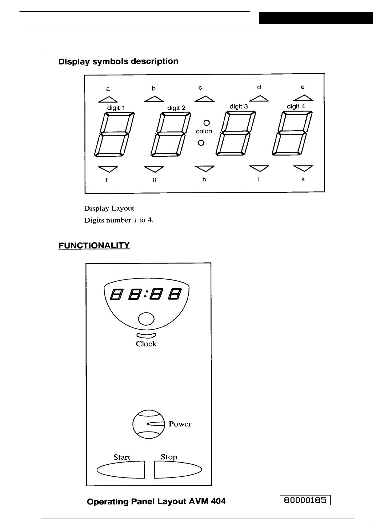
07.05.1998 / Page 4 AVM 683 Whirlpool Europe
Doc. No: 4812 714 12351 8538 683 01791 Customer Service
Text/Legend
SERVICE
Page 5

Whirlpool Europe AVM 683 07.05.1998 / Page 5
SERVICE
Power Up
When the unit is powered up, STANDBY mode is set and only the colon is lit.
Real Time Clock
A special key on the panel is dedicated for setting RTC. 12/24h clock is selected by means of an option diode.
Clock-key from STANDBY: The two leftmost digits of the display will blink and hours can be set by turning the
Rotacoder. If RTC not previously set, the display will initiate to 1:00 if 12-hour clock, and 00:00 if 24-hour
clock.
Clock-key from hour setting: The two rightmost digits of the display will blink and minutes can be set by
turning the Rotacoder.
Clock-key from minute setting: Clock will be set to selected time, seconds will be cleared (set to 00) and
oven will return to STANDBY.
Pressing STOP-key while in RTC-set, will inhibit RTC, return oven to STANDBY and only colons will display.
TIME-OUT, 30 seconds (10 minutes with door open) while in RTC-set, will inhibit RTC and return oven to
STANDBY.
If RTC previously set, the previous time will be retained (time will continue to update while in RTC-set).
If RTC NOT previously set, only colons will display.
Customer Service 8538 683 01791 Doc. No: 4812 714 12351
Hour setting 12 hour clock series: 1-12.
Hour setting 24 hour clock series: 00-23.
Minute setting: 00-59.
Hours and minutes are separated with a colon on display.
For 12 hour clock, when hour < 10 the leftmost digit will be blank.
Turning Rotacoder clockwise will increase minutes/hours.
Turning Rotacoder counter-clockwise will decrease minutes/hours.
RTC-set can only be reached from STANDBY.
Cooking-Timer (CT)
Whenever not in RTC-set, the Rotacoder will control the CT.
Turning Rotacoder clockwise will increase minutes/seconds.
Turning Rotacoder counter-clockwise will decrease minutes/seconds.
Max. time 90.00
Min. time 0.00
CT when turning Rotacoder resolution:
0-60 s, 5 s steps
1-3 min, 15 s steps
3-6 min, 30 s steps
6-30 min, 1 min steps
30-90 min, 5 min steps
- When CT normal resolution is displayed, seconds and minutes will be separated with the lower dot on the
display.
- When CT 1-second resolution(see below) is displayed, seconds and minutes will be separated with the upper
dot on the display.
A time < 10.00 minutes will be displayed with 3 digits, e.g. 5 seconds as ” 0.05”, lleaving the leftmost digit
blank.
Cooking-Timer (Ct) 1-Second Resolution
When adjusting the CT, 1-second resolution can be achieved by pressing the Clock-key whenevercookingtime
is displayed.
CT: 0.00 - 30.00 => 1 second resolution.
CT: 30.00 - 90.00 => 1 minute resolution.
Leaving 1-second resolution can be done in any of the following ways:
1. The 1-second resolution has a 30 second TIMEOUT from (EVENT or POWERCH),thatwillforcetonormalresolution.
2. Pressing the Clock-key while in 1-second resolution, will force to normal resolution.
3. STANDBY, will force to normal resolution.
Page 6

07.05.1998 / Page 6 AVM 683 Whirlpool Europe
Doc. No: 4812 714 12351 8538 683 01791 Customer Service
Cooking
COOKING is initiated only by pressing the START-key. If STARTOK and the door is closed, the COOKING
procedure is allowed to start.
When COOKING, the selected MODE will be used and the decreasing CT is displayed.
F/L-Relay will be ON or/and MW relay will be on according to the
The CT is always possible to change by means of the Rotacoder or ADD30SEK.
Pressing the STOP-key will initiate the oven to STANDBY.
Cooking-Finished
When CT reaches 0.00 while COOKING, the oven will initiate COOKING-FINISHED, beep 3 times and initiate
TIME-OUT to 10 minutes. During COOKING-FINISHED, ”End” will show steady on the display.
The 3 Beep’s will be repeated once a minute until leaving COOKING-FINISHED.
Leaving COOKING-FINISHED can be done in any of the following ways:
1 TIME-OUT. After 10 minutes the oven will initiate to STANDBY.
2 STOP-key. Pressing the STOP-key will initiate the oven to STANDBY.
3 Open door. When the door is opened, buzzer will be stopped and COOKING- INTERRUPTED will be
initiated.
4 START-key pressed. Oven will retain the previous MODE, initiate to 30 seconds and start.
SERVICE
The following actions will clear the ”End” display, stop the buzzer and initiate TIME-OUT to 30
seconds, but COOKING-FINISHED will still be retained.
1 Rotacoder moved to the right. When Rotacoder is moved to the right, the previous MODE is retained and
the new CT is displayed.
NOTE: Rotacoder moved to the left will initiate TIME-OUT to 10 minutes (mask2) and stop the buzzer,but NOT
clear ”End” display.
2 POWERCH, will initiate oven to MW . CT will be initiated to ( ” 0.05”) and show on display.
3 RTS-key pressed. CT, ( ” 0.00”) will be displayed and 1 second resolution mode will be set or cleared,
depending on previous state.
Cooking-Interrupted
When the door is opened during COOKING, COOKING-INTERRUPTED will be initiated.
The CT will be stopped and displayed.
Leaving COOKING-INTERRUPTED can be done in the following ways:
1 TIME-OUT. After 10 minutes and door open (30 seconds with door closed), the oven will initiate to STANDBY.
2 STOP-key. Pressing the STOP-key will switch off the F/L relay and
initiate oven to STANDBY.
3 Close door. Closing the door will force the ovento previous MODE,
showing CT and NOT COOKING.
Add 30sek
ADD30SEK is initiated under two circumstances:
1 Pressing the START-key while oven is COOKING, will add 30 seconds to CT.
2 Pressing the START-key when CT = 0.00(not necessary displayed, e.g. ”End” is displayed) and oven NOT in
RTC-set, will add 30 seconds to CT.
Oven will start COOKING if door is closed and STARTOK flag is true.
Standby
When in STANDBY, Real Time Clock will be displayed if RTC is set, otherwise display will be blank (Colons on).
- Buzzer will be off.
- If door is closed and STANDBY, all relays will be off.
Page 7

Whirlpool Europe AVM 683 07.05.1998 / Page 7
SERVICE
Mode
Whenever MODE is initiated, CT will be displayed.
From STANDBY, MODE will be initiated by the following actions:
1. Moving the Rotacoder will initiate CT to ” 0.05”.
2. Moving the POWER selector(POWERCH) will initiate CT to ” 0.05”.
When in MODE and CT = ” 0.00”, POWERCH will initiate CT to ” 0.05”.
Leaving MODE to STANDBY can be done in the following ways:
1. COOKING-FINISHED and TIME-OUT. After 10 minutes the oven will initiate to STANDBY.
2. STOP-key. Pressing the STOP-key will initiate the oven to STANDBY.
3. Not COOKING and TIME-OUT (door closed). After 30 seconds the oven will initiate to STANDBY.
4. Door open and TIME-OUT. After 10 minutes the oven will initiate to STANDBY.
MW
When COOKING, the MW-powerlevel used will be the one currently pointed at by the power selector.
Customer Service 8538 683 01791 Doc. No: 4812 714 12351
Power Change
When change of power occurs by turning the POWER-knob, the new power will be conditionally accepted at
the beginning of the next cookcycle.
Cookcycle
Used for MW-power average algorithms. One cookcycle = 20.5 seconds (50Hz).
Jet (Mask2 functionality)
At start of COOKING, MW-mode selected and full power selected, ”Jet” will show for 2 sec on display, and
thereafter actual CT will display.
On EVENT or POTPCH, selected CT will immediately show on the display, turning ”Jet” indication off.
When COOKING and JET condition becomes true as above, i.e. POWER selector
has been moved, ”Jet” will display for 2 sec, and thereafter actual CT will display.
Event
EVENT is asserted at any of the following occurrences:
1. Key is pressed
2. Door is closed
3. Door is opened
4. Rotacoder moved
Door Time-Out (Childlock)
When oven detects an uninterrupted STANDBY for >= 60 sec and door closed, STARTOK flag will be false.
Show ”Door” On Display (Childlock)
If STARTOK flag is false when START-key pressed, oven will display ”door” for 2 sec, and thereafter show the
selected cooking-time. Oven will NOT start COOKING.
On EVENT(except START-key), ”door” display will be cleared, and selected CT will be displayed.
F/L-Relay Functionality
The F/L-relay functionality is depending on option diode selection pos 6274, according to table below.
Page 8

07.05.1998 / Page 8 AVM 683 Whirlpool Europe
Doc. No: 4812 714 12351 8538 683 01791 Customer Service
FUNCTION MWO
STANDBY, closed door F/L off
STANDBY, open door F/L off
COOKING F/L on
COOKING INTERRUPTED F/L on
(door open)
COOKING INTERRUPTED F/L off
(door opened, then closed)
COOKING INTERRUPTED F/L off
(door opened, closed, opened)
COOKING FINISHED F/L on
COOKING FINISHED F/L on
(door open)
COOKING FINISHED F/L off
(door opened, then closed)
SERVICE
COOKING FINISHED F/L off
(door opened, closed, opened)
MW-Power Reduction
After 30min of cooking with a power-level of >= 750W,
MW-power will be reduced to 750W.
Reset
At total reset (memory lost), oven will clear all memory positions and initiate to STANDBY.
RTC will be cleared.
MICROWAVE POWER CONTROL
The peak microwave power is specified in the technical specification of the oven. To get lower power levels,
the magnetron is switched on and off. The magnetron is on during a portion of the cycle time, then it is
switched off until the beginning of the next cycle. The on-time varies depending on which power level has
been selected, see tables below.
Page 9

Whirlpool Europe AVM 683 07.05.1998 / Page 9
SERVICE
MW-POWER TABLE VIP20 50Hz (20.5sek cycletime)
Customer Service 8538 683 01791 Doc. No: 4812 714 12351
Power On/Start Power Remark
1 3.7/1.5s 90W
2 5.4/1.5s 160W DEFROST
3 9.9/1.4s 350W
4 13.4/1.3s 500W
5 16.8/1.1s 650W
6 18.7/0.6s 750W
7 24.0/0.0s 850W JET Peak power
CIRCUIT DESCRIPTION
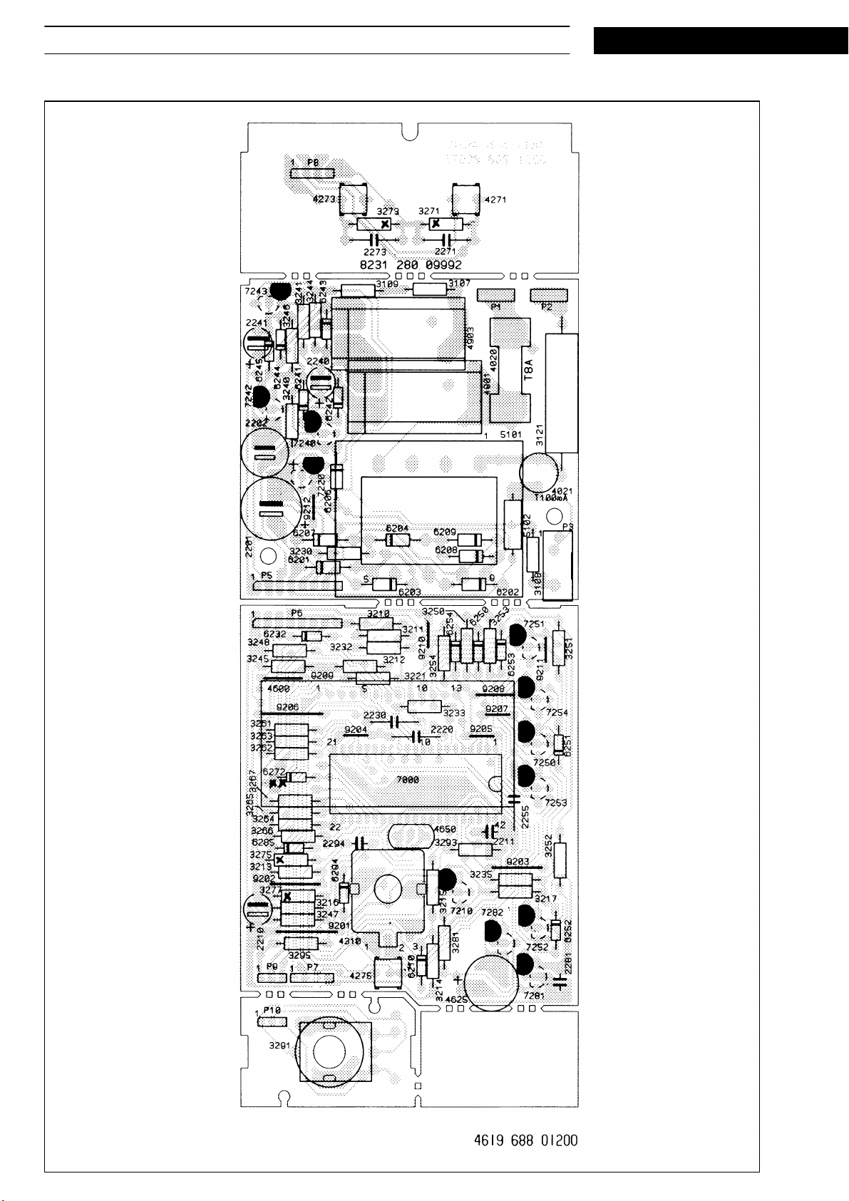
Transformer and Rectifier
The voltages necessary to the control system are taken from transformer 5101. It has two secondary windings,
one 8 V (RMS.) to supply the display and buzzer and one 33V (RMS.) winding to supply the rest of the circuits.
There is a thermal overload protection included in the transformer, to avoid insulation breakdown in the case of
short circuits on the secondary side. The primary and secondary circuits are completely isolated from each
other.
Relays
There are three relays to control the oven: and 4901to control the cavity illumination, the fan and the turn table
motor. 4903 to control the high voltage transformer and 4904 to control the grill element.
Microprocessor
The oven is controlled by a single chip microcomputer.It contains RAM and ROM, timer and a clockgenerator.
33 input and output ports are used to control the display and the relays, to read the keyboard matrix, the power
and mode potentiometers, the rotary encoder, door status, the frequency of the mains and to generate 2048
Hz for the buzzer. The clock generator uses an external ceramic resonator to keep an accurate frequency of
4.19 Mhz.
Voltage Regulator and Reset Circuit
The voltage between VDD and VSS is regulated by zener diode 6210 and the base-emitter voltage of the
transistor 7210. At start-up the transistor is not conducting, so the reset-pin of 7000 is held low by the resistor
3216. When the voltage between VDD and VSS has increased to about 4 Volts, the base current of 7210 is
high enough to make the transistor conduct, and the reset-pin goes high.
The resistor 3215is used to manipulate with the reset level from the software.By pulling the port R81 low,the
reset can be masked when the program won’t allow reset.
Relay Driver Circuits
To prevent the relays from being activated if the processor is hung up, the relay driver is ac coupled. This
means that a pulse train on output R52 is necessary to activate relay 4901, 4903 and 4904. When any relay
shall be activated the output of R52 will deliver pulses t
When only cavity lamp is active (door open) the output of R52 will deliver pulses t
= 221 us and t
high
= 23 us when fan is operating.
low
= 1.9 ms and t
high
low
ms, to avoid noise generated when switching at the higher frequency.
Transistor 7243 and 7240 is switched on when R70 goes high and they are switched of when R70 goes low.
Capacitor 2240 and resistor 3244 forms an integrator. The voltage over capacitor 2240 is equal to the average
voltage over the relaycoils. When transistor 7240 is switched of the current in the relay coils continue to flow
=1.0
Page 10

07.05.1998 / Page 10 AVM 683 Whirlpool Europe
Doc. No: 4812 714 12351 8538 683 01791 Customer Service
through the diodes 6240(grill), 6241 and 6242. The positive pole of 2240 goes to minus 0,6 V. If the voltage
over 2240 exceeds the zenervoltage of 6243 the zenerdiode will conduct and when R70 goes high and the
transistors 7243 and 7240 will not switch on.
50 Hz Sensing Circuit
The 50 Hz-signal is taken from the 8V secondary winding of the mains transformer, before the rectifier. When
the transformer voltage is about 0.6 V lower than VDD the diode in position 6232 will conduct and capacitor
2230 will discharge. If 6232 is not conducting the capacitor 2230 will be charged through resistor 3232. The
port R50 (an I/O port) is kept low except when the 50 Hz signal is sampled once a millisecond. The R50 is let
high and if capacitor 2230 is charged the processor will read a high level.
Feedback Circuit (OPTO-feedback)
The primary side of the feed back circuit consists of six resistors 3101 - 3106, diode 6101 and the transmitter
diode in opto-coupler 7101.
When the door is open, no current flows through the transmitter diode, and the photo transistor in 7101 is not
conducting. The transistor 7220 is switched on and the collector goes low.
If the door is closed and the MW relay is not activated, a current will flow through the transmitterdiode in 7101
when live is negative. In this case transistor 7220 is switched of and the collector is high.
When the door is closed and MW relay is activated the collector of 7220 will be low when live is positive.
SERVICE
Feedback Circuit (RESISTOR-feedback)
The feed back circuit consists of four resistors 3107-3109 3221, a transistor 7220, a capacitor 2220 and a coil
5102.
When door is open, a current will flow from the coil through P5-P2 and through 3108-3109, turning 7220 on
and pulling port R53 low.
When door is closed and MW relay not activated , the current path will be disrupted, turning 7220 off.
When door is closed and MW relay activated, there is a current path through the voltage divider 3107-3109.
This will turn 7220 on in the high time of the period and off in the low part.
Keys
To encode different versions of the oven , one or more of the diodes 6271-6282 may be present. These are
scanned in a manner similar to the key switches.
Refer to Test-mode description below for option diode functionality.
The keys (Stop, Start, Clock) are connected to port K00, K01, K02 respectively, and in common to port P20
through diode 6285.
When scanning, port P20 will be pulled low, allowing port K00-K02 to turn low when the corresponding key is
pressed. If no key is pressed the processor will recognise a high level on K00-K02. All K inputs have internal
pull-up resistors (not on OTP’s).
Display
The LED display is driven via transistors 7250 - 7254. The output ports R40, R41, R42, R43 and R90 is let high
one at the time. Base current is supplied from the 33 V supply. The base voltage is limited to VDD + 0,6 V by
the diodes 6250 - 6254. The output port P10 - P13 and P20 - P23 control which LED segment that should be
on.
Buzzer
The buzzer (4625) is of the electrodynamic type. It is driven by transistor 7281 and 7282. transistor 7281
stabilise the buzzer supply to a voltage 0,6 V below VDD. When the buzzer sounds, the base of 7282 is fed
with a 2048 Hz square wave from the microprocessor.
Page 11

Whirlpool Europe AVM 683 07.05.1998 / Page 11
SERVICE
Rotacoder
The rotacoder (4310) is connected to ports K03(input) and R72, R73(output). When turning the rotacoder, the
pins A-C and B-C will be connected internally in a defined way. Depending of the direction of the turn A-C or BC will be connected first.
Normally the ports R72, R73 is in high impedance-state. When scanning, the output ports will be pulled low
one at a time and K03 will be sensed for a low level, to detect if a connection has been made between A-C or
B-C.
The rotacoder is scanned each 1ms.
Potentiometers
The potentiometer sensoring works as follows: Normally port R82 is in a high impedance state. This will
charge capacitor 2294 to a level of (almost) VDD, through diode 6294. When a measurement is taking place,
port R82 will turn low to stop any current-flow through 6294. At the same time one of the ports R60, R61 is
pulled low to allow the capacitor 2294 to discharge through one lead of the potentiometer. While the capacitor
is discharging, the potential at port R80 (input) will decrease, and when the voltage level reaches the threshold
for interpreting a low level at the port, the discharging will stop and the time from the start of the discharging
will be measured.
Port R82 will turn high again to allow 2294 to charge, and the process is repeated for the other potentiometer
lead. The quotient of the two measured times will then decide, at which position the potentiometer points.
The total process is than repeated for the other potentiometer (AVM441, 446).
Customer Service 8538 683 01791 Doc. No: 4812 714 12351
AVM404: EASYTRONIC MWO.
Power levels: 90W, 160W*), 350W, 500W, 650W, 750W, 900W.
*) Defrost = 160W.
Common functions:
Keys: Start, Stop, Clock.
Potentiometers: Power-level selector
Rotacoder.
Real Time Clock 12/24h.
Cooking timer max. 90.00 min.
LED display.
DEFINITIONS AND ABBREVIATIONS
ADD30SEK Add 30 seconds to CT
CT Cooking Time(er)
MODE MW
F/L Fan and cavity Lamp
JET Overriding function, MW full power *) mask2: not overriding
Mask 1 P/N 4619 678 43161 (Not used in AVM 404)
Mask 2 P/N 4619 678 43621
MW Micro Wave
MWO Micro Wave Only
POWERCH POWER Potentiometer (selector) Changed (moved)
RTC Real Time Clock
STARTOK Door is closed within 1 minute (childlock)
TT Turn Table
Page 12

07.05.1998 / Page 12 AVM683 Whirlpool Europe
Doc. No: 4812 714 12351 8538 683 01791 Customer Service
SERVICE
Spare part list
Model AVM 683
Service No. 853868301791
Version 853868301791
Pos. No. 12NC Code Description from to
002 0 4819 440 59471 Cabinet
002 2 4819 462 79939 Cover
004 0 4819 462 79937 Plate Bottom
010 0 4819 310 39634 Mounting frame set
013 0 4819 462 79423 Foot
013 1 4819 462 79938 Foot right back
041 0 4819 417 19248 Hinge,lower
042 0 4819 417 19514 Hinge,upper
100 0 4819 442 39368 Door cpl.
120 0 4819 459 48654 Door frame inner
130 0 4819 271 38148 Unit,pushbutton
130 2 4819 466 89172 Clip
141 0 4819 450 58095 Oven glass
143 0 4819 459 48905 Door frame outer
255 0 4819 466 78218 Turntable glass
264 0 4819 535 78156 Crosspiece
320 0 4819 453 59149 Control panel
332 0 4819 410 29001 Button
332 2 4819 410 29002 Button
334 3 4819 412 58669 Knob feature/power
334 4 4819 412 58671 Knob
334 9 4819 492 68796 Spring
352 0 4819 130 38081 Display
352 1 4819 450 58107 Glass panel display
355 0 4819 280 18033 Buzzer
404 0 4819 131 58019 Magnetron
404 2 4819 462 38839 Air guide
406 0 4819 361 18292 Motor for rotary plate
406 2 4819 532 68686 Gasket ring
411 0 4819 148 68085 Transformer
412 0 4819 145 78197 Transformer,HT
420 0 4819 121 48016 Capacitor HT
421 0 4819 121 18197 Filter mains
421 0 4819 404 79272 Holder for capacitor
426 0 4819 218 38038 Diode HV
442 0 4819 361 18313 Motor fan
443 0 4819 310 39025 Fan
443 1 4819 462 38841 Air guide ventilation
485 0 4819 320 28037 Cable,HT
490 0 4819 321 18136 Cable,mains 2m
502 0 4819 214 78572 Control unit
502 1 4819 113 88001 Resistor 100 Ohm
502 3 4819 101 48146 Potentiometer
502 4 4819 101 48142 Potentiometer
505 0 4819 209 88054 Microprocessor
561 0 4819 282 48281 Thermostat for magnetron 125 C
617 0 4819 280 68321 Relay
622 0 4819 276 18273 Switch VKS
633 0 4819 271 38145 Microswitch
651 0 4819 134 28029 Lamp cavity 240V - 25W
910 0 4819 502 18372 Screw for TT-Motor
910 1 4819 502 18499 Screw
910 2 4819 502 38274 Screw for trafo M4x16St
971 0 4819 252 28122 Fuse T8A
972 0 4819 252 28121 Fuse T100mA
Page 13
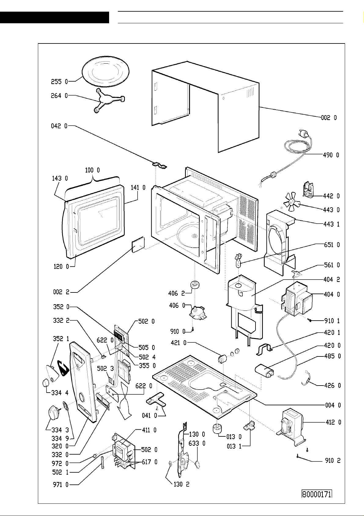
SERVICE
Exploded view
Whirlpool Europe AVM 683 07.05.1998 / Page 13
Customer Service 8538 683 01791 Doc. No: 4812 714 12351
Page 14
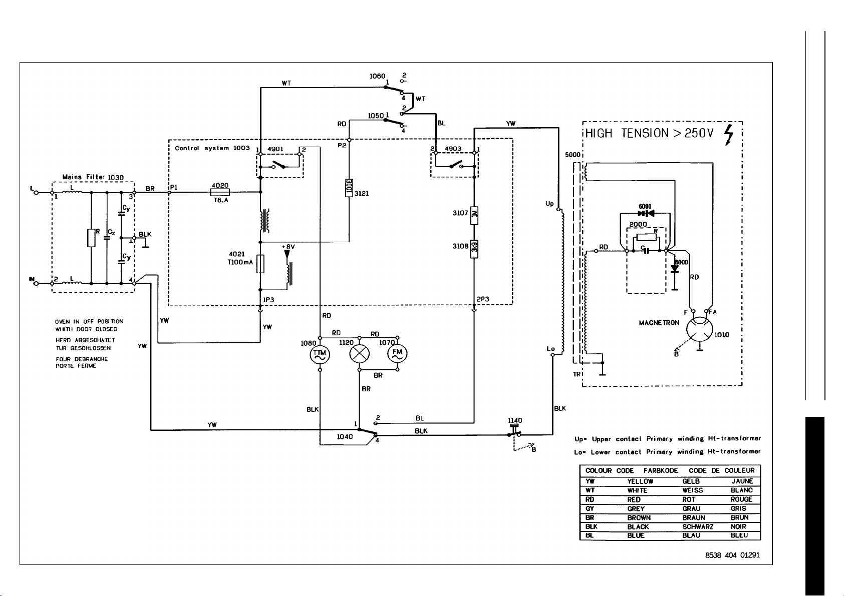
Wiring diagram
07.05.1998 / Page 14 AVM 683 Whirlpool Europe
Doc. No: 4812 714 12351 8538 683 01791 Customer Service
1003 Control System
1010 Magnetron
1030 Mainsfilter
1040 Secondary doorswitch
1050 Monitor doorswitch
1060 Primary doorswitch
1070 Motor fan
1080 Motor turntable
1120 Oven lamp
1140 Thermostat magnetron
2000 HT capacitor
4020 Fuse T8.0 A
4021 Fuse T100 mA
5000 HT transformer
6000 HT diode
SERVICE
Page 15
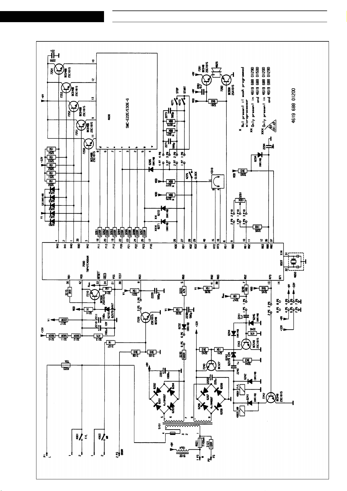
SERVICE
Program diagram
Whirlpool Europe AVM 683 07.05.1998 / Page 15
Customer Service 8538 683 01791 Doc. No: 4812 714 12351
Page 16
07.05.1998 / Page 16 AVM 683 Whirlpool Europe
Doc. No: 4812 714 12351 8538 683 01791 Customer Service
Program diagram
SERVICE
 Loading...