


Service Manual
ViewSonic VE175-2
VE175b-2
Model No. VLCDS23895-6W/7W
17” Color TFT LCD Display
QDI (A2KYYWW00001 ~ 50000) (A2UYYWW00001 ~ 50000)
CPT (A2KYYWW50001 ~ 99999 ) (A2UYYWW50001 ~ 99999)
(VE175-2/ VE175b-2_SM_746 - Rev. 1b – Aug. 2003)
ViewSonic 381 Brea Canyon Road, Walnut, California 91789 USA - (800) 888-8583

Copyright
Copyright ¤ 2003 by ViewSonic Corporation. All rights reserved. No part of this publication may be reproduced, transmitted, transcribed, stored in a retrieval system, or translated into any language or computer language, in any form or by any means, electronic, mechanical, magnetic, optical, chemical, manual or otherwise, without the prior written permission of ViewSonic Corporation.
Disclaimer
ViewSonic makes no representations or warranties, either expressed or implied, with respect to the contents hereof and specifically disclaims any warranty of merchantability or fitness for any particular purpose. Further, ViewSonic reserves the right to revise this publication and to make changes from time to time in the contents hereof without obligation of ViewSonic to notify any person of such revision or changes.
Trademarks
Optiquest is a registered trademark of ViewSonic Corporation. ViewSonic is a registered trademark of ViewSonic Corporation.
All other trademarks used within this document are the property of their respective owners.
Revision History
Revision |
Date |
Description Of Changes |
Approval |
1a |
17/06/02 |
Initial Release DCN2251 |
WANGJE |
1b |
14/08/03 |
Revised DCN3760 |
Teddy.Liaw |
|
|
|
|
|
|
|
|
|
|
|
|
|
|
|
|
|
|
|
|
|
|
|
|
ViewSonic Corporation |
! |
i |
|
|
|
! |
Confidential – Do Not Copy |
VE175/b-2 |
|||
|

|
TABLE OF CONTENTS |
|
1. |
PRECAUTIONS AND SAFETY NOTICES.......................................................... |
1 |
2. |
SPECIFICATIONS ............................................................................................... |
2 |
3. |
FRONT PANEL FUNCTION CONTROL DESCRIPTION..................................... |
4 |
4. |
CIRCUIT DESCRIPTION...................................................................................... |
10 |
5. |
ADJUSTING PROCEDURE ................................................................................ |
15 |
6. |
TROUBLE SHOOTING FLOW CHART .............................................................. |
17 |
7. |
EXPLODED DIAGRAM........................................................................................ |
21 |
8. |
EXPLODED PARTS LIST ................................................................................... |
23 |
9. |
BLOCK DIAGRAM ............................................................................................. |
25 |
10. |
SCHEMATIC DIAGRAM..................................................................................... |
26 |
11. PCB LAYOUT ..................................................................................................... |
32 |
|
12. RECOMMENDED SPARE PARTS LIST.......................................................... |
38 |
|
ViewSonic Corporation |
! |
ii |
|
|
|
! |
Confidential – Do Not Copy |
VE175/b-2 |
|||
|

1.Precautions and Safety Notices
1.1.SAFETY PRECAUTIONS
This monitor is manufactured and tested on a ground principle that a user's safety comes first. However, improper use or installation may cause damage to the monitor as well as to the user. Carefully go over the following WARNINGS before installing and keep this guide handy.
WARNINGS:
This monitor should be operated only at the correct power sources indicated on the label on the rear end of the monitor. If you're unsure of the power supply in your residence, consult your local dealer or Power Company.
Do not try to repair the monitor your self as it contains no user-serviceable parts. This monitor should only be repaired by a qualified technician.
Do not remove the monitor cabinet. There is high-voltage parts inside that may cause electric shock to human bodies, even when the power cord is unplugged.
Stop using the monitor if the cabinet is damaged. Have it checked by a service technician.
Put your monitor only in a clean, dry environment. If it gets wet, unplug the power cable immediately and consult your service technician.
Always unplug the monitor before cleaning it. Clean the cabinet with a clean, dry cloth. Apply non-ammonia based cleaner onto the cloth, not directly onto the glass screen.
Keep the monitor away from magnetic objects, motors, TV sets, and transformer.
Do not place heavy objects on the monitor or power cord.
1.2.PRODUCT SAFETY NOTICE
Many electrical and mechanical parts in this chassis have special safety visual inspections and the protection afforded by them cannot necessarily be obtained by using replacement components rated for higher voltages, wattage, etc. Before replacing any of these components read the parts list in this manual carefully. The use of substitute replacement parts which do not have the same safety characteristics as specified in the parts list may create shock, fire, or other hazards.
1.3.SERVICE NOTES
1.When replacing parts or circuit boards, clamp the lead wires around terminals before soldering.
2.When replacing a high wattage resistor (more than 1W of metal oxide film resistor) in circuit board, keep the resistor about 5mm away from circuit board.
3.Keep wires away from high voltage, high temperature components and sharp edges.
4.Keep wires in their original position so as to reduce interference.
5.Usage of this product please refers to also user's manual.
ViewSonic Corporation |
! |
1 |
|
|
|
! |
Confidential – Do Not Copy |
VE175/b-2 |
|||
|

2. Specification
2.1. PRODUCT SPECIFICATIONS
LCD Panel |
17.0" TFT |
Power Management |
Energy Star compliant VESA |
|
DPMS compatible |
|
< 2W |
Displayable Resolution |
SXGA 1280× 1024 (max.) |
Pixel Dimension |
0.264(H)× 0.264(V)mm |
LCD Display Color |
16.2M Color Max. (6bit + FRC) |
Viewing Angle |
CR 10 |
|
Horizontal: 70°+70° |
|
Vertical: -65°+65° |
Tilt |
+90°, -3° |
Contrast Ratio |
450 : 1 (typ.) 360:1 (min.) |
Brightness |
240 cd/ m2 (min.) |
|
300 cd/m2 (typ.) |
Response Time |
Tr: 9 ms Tf: 16 ms (typ.) |
|
Tr: 18 ms Tf: 32 ms (max.) |
Active Display Area |
337.920mm(H)× 270.336mm(V) |
Temperature |
Operating: 0°C ~ +40°C |
|
Storage: -20°C ~ +60°C |
Compliance |
UL 1950, cUL, EN60950, FCC-B, CE MARK, TÜV/GS, TCO99, CB. |
Power |
Input Voltage: 100~240 Vac |
|
Consumption: 50 Watts (Max.) |
2.2. FACTORY SUPPORTING MODES
Primary Preset: |
VESA 1280 x 1024 @ 60Hz |
||
Look up table timing: |
1. |
IND 640 x 350 @ 70Hz, 31.47kHz, -/+ |
|
|
2. |
IND 720 x 400 @ 70Hz, 31.467kHz, +/- |
|
|
3. |
VESA 640 x 480 @ 60Hz, 31.469kHz, -/- |
|
|
4. |
VESA 640 x 480 @ 72Hz, 37.861kHz, -/- |
|
|
5. |
VESA 640 x 480 |
@ 75Hz, 37.5kHz, -/- |
|
6. |
MAC 640 x 480 @ 67Hz, 35kHz. |
|
|
7. |
VESA 800 x 600 |
@ 56Hz, 35.156kHz, +/+ |
|
8. |
VESA 800 x 600 |
@ 60Hz, 37.879kHz, +/+ |
|
9. |
VESA 800 x 600 |
@ 72Hz, 48.077kHz, +/+ |
ViewSonic Corporation |
! |
2 |
|
|
|
! |
Confidential – Do Not Copy |
VE175/b-2 |
|||
|
10.VESA 800 x 600 @ 75Hz, 46.875kHz, +/+
11.MAC 832 x 624 @ 75Hz, 49.725kHz.
12.VESA 1024 x 768 @ 60Hz, 48.363kHz, -/-
13.VESA 1024 x 768 @ 70Hz, 56.476kHz, -/-
14.VESA 1024 x 768 @ 72Hz, 58.036kHz, -/-
15.VESA 1024 x 768 @ 75Hz, 60.023kHz, +/+
16.MAC 1024 x 768 @ 75Hz, 60.241kHz.
17.VESA 1280 x 1024 @ 60Hz, 63.981kHz, +/+
18.VESA 1280 x 1024 @ 75Hz, 79.976kHz, +/+
19.MAC 1152 x 870 @ 75Hz, 68.6kHz.
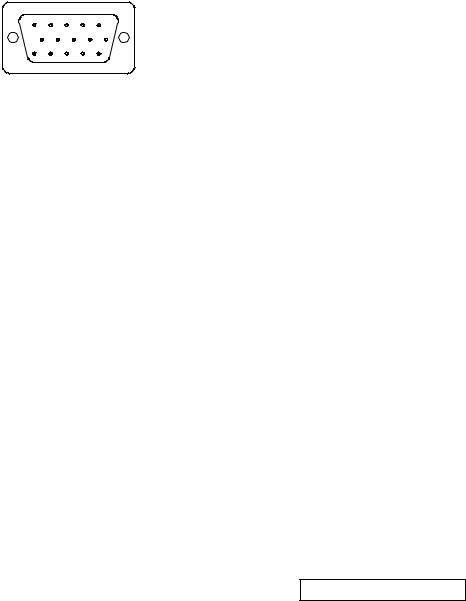
2.3. D-SUB CONNECTOR
D-SUB 15 PIN CONNECTOR
|
|
|
|
|
1.R |
6.GND |
11.NC |
|
1 |
2 |
3 |
4 |
5 |
2.G |
7.GND |
12.SDA |
|
6 |
7 |
8 |
9 |
10 |
||||
3.B |
8.GND |
13.H.SYNC |
||||||
11 |
12 |
13 |
14 |
15 |
||||
|
|
|
||||||
|
|
|
|
|
4.NC |
9. +5V |
14.V.SYNC |
|
|
|
|
|
|
5.GND |
10.GND |
15.SCL |
SIGNAL LEVEL
CONNECTOR |
SIGNAL |
DESCRIPTION |
|
|
|
R |
RED |
0.7vp-p(VIDEO) |
|
|
|
G |
GREEN |
0.7vp-p(VIDEO) |
|
|
|
B |
BLUE |
0.7vp-p(VIDEO) |
|
|
|
H |
H/SYNC |
TTL positive or negative |
|
|
|
V |
V/SYNC |
TTL positive or negative |
|
|
|
SDA |
DDC1/2B |
TTL |
|
|
|
SCL |
DDC1/2B |
TTL |
|
|
|
ViewSonic Corporation |
! |
3 |
|
|
|
! |
Confidential – Do Not Copy |
VE175/b-2 |
|||
|

3. Front Panel Function Control Description
Main Menu
with OSD controls
Displays, saves changes to, and exits the Main Menu.
Front Control Panel
Power light
Power On/Off
Scrolls through menu options and adjusts the displayed control.
Selects a highlighted control. Also, displays the control screen for the selected control and toggles between control pairs.
ViewSonic Corporation |
! |
4 |
|
|
|
! |
Confidential – Do Not Copy |
VE175/b-2 |
|||
|
Do the following to adjust the screen image:
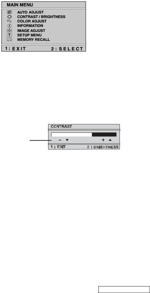
1To display the Main Menu, press button [1].
NOTE: All OSD menus and adjustment screens disappear automatically after about 30 seconds. This time period is adjustable through the Setup menu and the OSD timeout control described.
2To highlight a control you want to adjust, press ▲ or ▼ to scroll up or down the Main Menu.
3To select the highlighted control, press button [2]. A control screen appears like the example shown below.
The ▼ down arrow decreases Contrast, ▲ up arrow increases Contrast.

 The line at the bottom of the screen tells you what you can do next: select the Brightness control or Exit.
4To adjust the control, press the up ▲ or down ▼ buttons.
5To save the adjustments and exit the menu, press button [1] twice.
The following tips may help you optimize your display:
•Adjust your computer's graphic card so that it outputs a video signal 1280 x 1024 @ 60 Hz to the LCD display. (Look for instructions on “changing the refresh rate” in your graphic card's user guide.)
•If necessary, make small adjustments using H POSITION and V POSITION until the screen image is completely visible. (The black border around the edge of the screen should barely touch the illuminated “active area” of the LCD display.)
ViewSonic Corporation |
! |
5 |
|
|
|
! |
Confidential – Do Not Copy |
VE175/b-2 |
|||
|
Main Menu Controls
Adjust the menu items shown below by using the up ▲ and down ▼ buttons.
Control Explanation
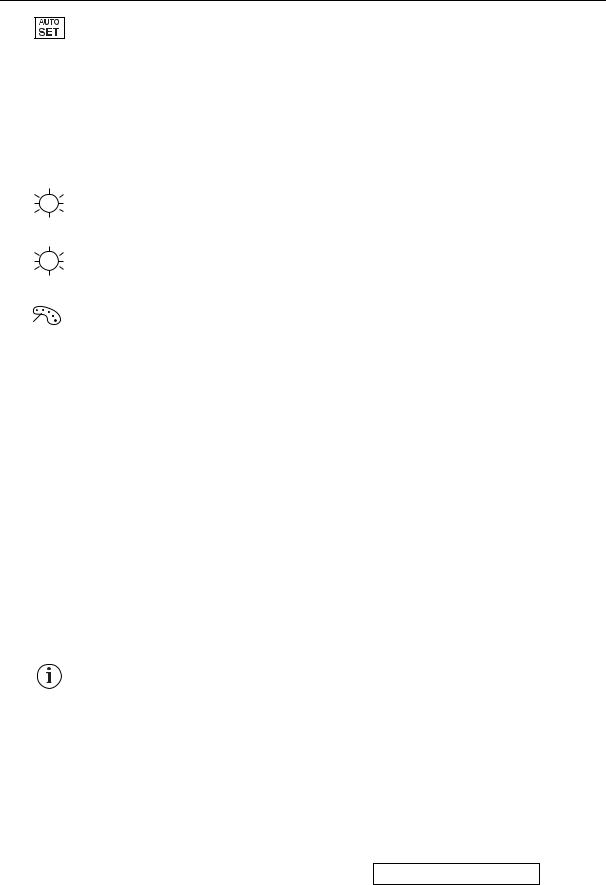
Auto Adjust automatically sizes, centers, and fine tunes the video signal to eliminate waviness and distortion.
Press the [2] button to obtain a sharper image.
NOTE: Auto Adjust works with most common video
cards. If this function does not work on your LCD display, then lower the video refresh rate to 60 Hz and set the resolution to its pre-set value.
Contrast adjusts the difference between the image background (black level) and the foreground (white level).
Brightness adjusts background black level of the screen image.
Color Adjust provides several color options: preset color temperatures and User which allows you to adjust red (R), green (G), and blue (B). The factory setting for this product is 6500K (6500 Kelvin).
User — Individual adjustments for red, green, and blue.
5400K — Adds blue and green to the screen image for a darker color.
6500K — Adds red to the screen image for warmer white and richer red. Default setting.
9300K — Adds blue to the screen image for cooler white (used in most office settings with fluorescent lighting).
1 To select color (R, G or B) press button [2].
2To adjust selected color, press ▲ or ▼.
3When you are finished making all color adjustments, press button [1] twice.
Information displays the timing mode (video signal input) coming from the graphics card in your computer. See your graphic card’s user guide for instructions on changing the resolution and refresh rate (vertical frequency).
VESA 1280 x 1024 @ 60 Hz (recommended) means that the resolution is 1280 x 1024 and the refresh rate is 60 Hertz.
ViewSonic Corporation |
! |
6 |
|
|
|
! |
Confidential – Do Not Copy |
VE175/b-2 |
|||
|
Control Explanation
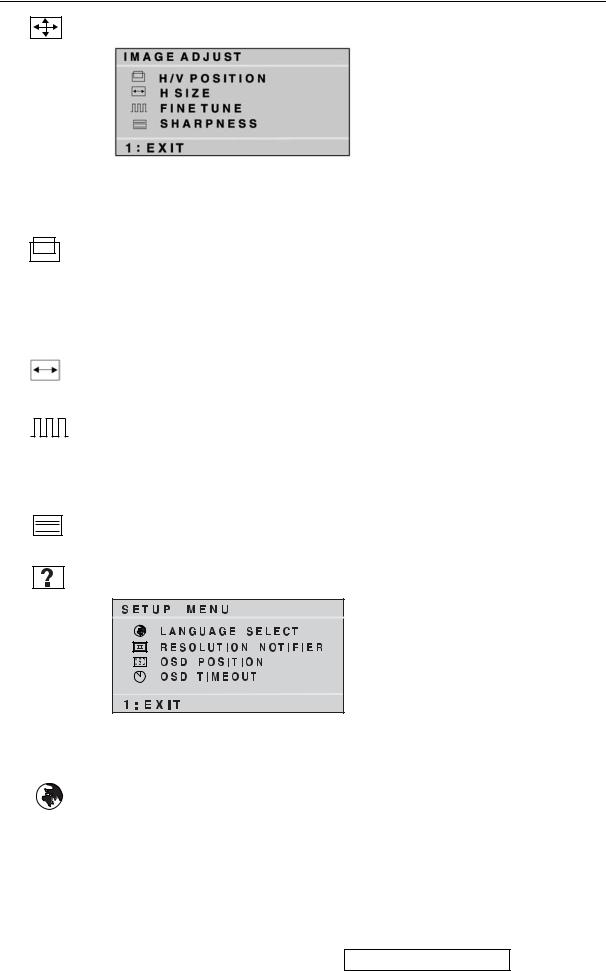
Image Adjust
The Image Adjust controls are explained below:
H./V. Position adjusts horizontal and vertical position of the screen image. You can toggle between Horizontal and Vertical by pressing button [2]. Horizontal moves the screen image to the left or to the right. Vertical moves the screen image up and down.
H. Size (Horizontal Size) adjusts the width of the screen image. Vertical size is automatic with your LCD display.
Fine Tune sharpens focus by aligning the illuminated text and/ or graphic characters.
Try the Auto Adjust (see page 9) before using the Fine Tune control.
Sharpness adjusts the clarity and focus of the screen image.
Setup Menu displays the menu shown below:
The Setup Menu controls are explained below:
Language Select allows you to choose the language used in the menus and control screens.
ViewSonic Corporation |
! |
7 |
|
|
|
! |
Confidential – Do Not Copy |
VE175/b-2 |
|||
|
Control Explanation
Resolution Notifier advises the optimal resolution to use.
OSD Position allows you to move the on-screen display menus and control screens.
OSD Timeout sets the length of time an on-screen display screen is displayed. For example, with a “15 second” setting, if a control is not pushed within 15 seconds, the display screen disappears.
Memory Recall returns adjustments to the original factory settings if the display is operating in a factory Preset Timing Mode listed in this user guide.
ViewSonic Corporation |
! |
8 |
|
|
|
! |
Confidential – Do Not Copy |
VE175/b-2 |
|||
|
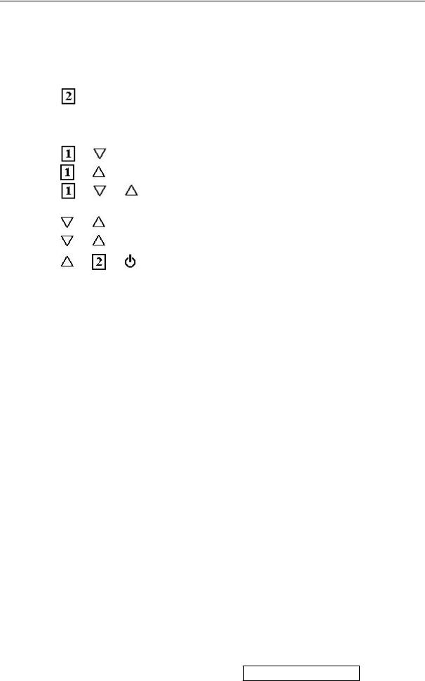
Short Cut Key
Function Key : 5 Key à 


 : Show OSD Menu or Exit OSD Menu.
 : Select down or decrease.(-)
 :Select up or increase(+).
: Select Or Enter.
 : Auto adjust. (When No OSD)
  : Power On/Off.
+ |
= Power key lock / unlock. |
|
+ |
= OSD lock / unlock. |
|
+ |
+ |
= Auto White Balance. |
|
|
(Remark: recommend to use 5-Disc full white pattern) |
+ |
= Recall Contrast and Brightness. (Don’t show OSD) |
|
+ |
+ No Signal = Enter Burn in mode |
|
+ |
+ |
(Power On) = Enter Maintain mode. |
ViewSonic Corporation |
! |
9 |
|
|
|
! |
Confidential – Do Not Copy |
VE175/b-2 |
|||
|

4.Circuit Description
A.DC-DC CONVERTER
The DC-DC converter converts the 12V input voltage to 5V for panel use, and 3.3V and 1.8V for controller use. It consists of a PWM IC (LM2596), flywheel Diode (B340), buck choke (L108), and capacitor C173.
I102 (LM2596) is a PWM generator working at 150KHz.
Self protection features include a two stage frequency reducing current limit for the output switch and an over temperature shutdown for complete protection under fault condition.
B.Scaling controller
The ADC is used to convert RGB analog signal to digital signal that scaling chip can acknowledge.
The HSYNC input receives a logic signal and provides the frequency reference for pixel clock generation.
The scaling IC converts the input signal ranging from VGA to SXGA into SXGA resolution that panel can acknowledge. When power is first applied, the ADE3XXX is asynchronously reset. The uC typically programs the ADE3XXX with a number of default values and sets up the ADE3XXX to identify activity on any of the input pins. All preconfigured values and RAMs, such as line-lock PLL settings, OSD characters, LCD timing values (output sequencer), scale kernels, gamma curves, sRGB color warp, APC dithering, output pin configuration (OMUX), etc. can be preloaded into the ADE3XXX. The typical end state is that the ADE3XXX is initialized into a low power mode, ready to turn active once the power button is pressed. When the monitor has been powered on, the inputs can be monitored for active video sources. Based on the activity monitors, the uC chooses an input or power down state.
Once an input source is selected, all available information on frequencies and line/pixel counts is measured for the selected source and made available to the uC.
MTV312M64
The MTV312M micro-controller is an 8051 CPU core embedded device especially tailored for CRT/LCD Monitor applications. It includes an 8051 CPU core, 1024-byte SRAM, 14 built-in PWM DACs, VESA DDC interface, 4-channel A/D converter, and a 64K-byte internal program Flash-ROM.
A “CMOS output pin” means it can sink and drive at least 4mA current. It is not recommended to use such pin as input function.
An “open drain pin” means it can sink at least 4mA current but only drive 10~20uA to VDD. It can be used as input or output function and needs an external pull up resistor.
A “8051 standard pin” is a pseudo open drain pin. It can sink at least 4mA current when output is at low level and drive at least 4mA current for 160nS when output transits from low to high, then keep driving at 100uA to maintain the pin at high level. It can be used as input or output function. It needs an external pull up resistor when driving heavy load devices.
POWER CONFIGURATION
The MTV312M can work on either 5V or 3.3V power supply system.
In 5V power system, the VDD pin is connected to 5V power and the VDD3 needs an external capacitor, all output pins can swing from 0~5V, input pins can accept 0~5V input range.
The ADC conversion range is 5V. However, X1 and X2 pins must be kept below 3.3V.
In 3.3V power system, the VDD and VDD3 are connected to 3.3V power, all output pins swing from 0~3.3V, HSYNC, VSYNC and open drain pin can accept 0~5V input range, other pins must be kept below 3.3V. The ADC conversion range is 3.3V.
C.INVERTER
In order to drive the CCFLs embedded in the panel module, there is a ROYER inverter to convert the input 12V up to hundreds of AC voltage output.
The inverter is formed by symmetric circuitry, in order to drive the separate lamp modules.
The input stage consists of a PWM controller, buck choke, and switching MOSFET to convert DC input into AC output.
The output stage consists of a tuning capacitor, transformer, and push-pull transistor pair to boost ac output up to hundreds of voltage.
There is also one resister in series with the lamp for output current feedback. A 6-pin connector is the only interface to control the inverter.
Pin 5/6 is 12V input, pin 1/2 is the returns, pin 3 is the control of output current, and pin 4 is the enable/disable control.
ViewSonic Corporation |
! |
10 |
|
|
|
! |
Confidential – Do Not Copy |
VE175/b-2 |
|||
|
 Loading...