


Service Manual
ViewSonic VA702-2
VA721-3
VA721b-3
Model No. VS10781-2
VS10781-3W
17” Color TFT LCD Display
(VA702-2_VA721-3_VA721b-3_SM Rev. 1a Mar. 2006)
ViewSonic 381 Brea Canyon Road, Walnut, California 91789 USA – (800) 888-8583
Copyright
Copyright © 2006 by ViewSonic Corporation. All rights reserved. No part of this publication may be reproduced, transmitted, transcribed, stored in a retrieval system, or translated into any language or computer language, in any form or by any means, electronic, mechanical, magnetic, optical, chemical, manual or otherwise, without the prior written permission of ViewSonic Corporation.
Disclaimer
ViewSonic makes no representations or warranties, either expressed or implied, with respect to the contents hereof and specifically disclaims any warranty of merchantability or fitness for any particular purpose. Further, ViewSonic reserves the right to revise this publication and to make changes from time to time in the contents hereof without obligation of ViewSonic to notify any person of such revision or changes.
Trademarks
Optiquest is a registered trademark of ViewSonic Corporation. ViewSonic is a registered trademark of ViewSonic Corporation.
All other trademarks used within this document are the property of their respective owners.
Revision History
|
Revision |
SM Editing Date |
ECR Number |
Description of Changes |
Editor |
|
|
|
|
|
|
|
|
|
1a |
03/06/2006 |
|
Initial Release |
Jamie Chang |
|
|
|
|
|
|
|
|
|
|
|
|
|
|
|
|
|
|
|
|
|
|
|
|
|
|
|
|
|
|
|
|
|
|
|
|
|
|
|
|
|
|
|
|
|
|
|
|
|
|
ViewSonic Corporation |
Confidential - Do Not Copy |
VA702-2_VA721-3_VA721b-3 |
i

TABLE OF CONTENTS
1. |
Precautions and Safety Notices |
1 |
|
|
|
2. |
Specification |
3 |
|
|
|
3. |
Front Panel Function Control Description |
11 |
|
|
|
4. |
Circuit Description |
14 |
|
|
|
5. |
Adjustment Procedure |
25 |
|
|
|
6. |
Troubleshooting Flow Chart |
30 |
|
|
|
7. |
Recommended Spare Parts List |
38 |
|
|
|
8. |
Exploded Diagram and Exploded Parts List |
43 |
|
|
|
9. |
Block Diagram |
47 |
|
|
|
10. |
Schematic Diagrams |
48 |
|
|
|
11. |
PCB Layout Diagrams |
56 |
|
|
|
ViewSonic Corporation |
Confidential - Do Not Copy |
VA702-2_VA721-3_VA721b-3 |
ii
1. Precautions and Safety Notices
SAFETY PRECAUTIONS
This monitor is manufactured and tested on a ground principle that a user’s safety comes first. However, improper used or installation may cause damage to the monitor as well as to the user.
WARNINGS:
•This monitor should be operated only at the correct power sources indicated on the label on the rear of the monitor. If you’re unsure of the power supply in you residence, consult your local dealer or Power Company.
•Use only the special power adapter that comes with this monitor for power input.
•Do not try to repair the monitor by yourself, as it contains no user-serviceable parts. Only the qualified technician can repair it.
•Do not remove the monitor cabinet. There are high-voltage parts inside that may cause electric shock to human bodies.
•Stop using the monitor if the cabinet is damaged. Have it checked by a service technician.
•Put your monitor only in a lean, cool, dry environment. If it gets wet, unplug the power cable immediately and consult your closed dealer.
•Always unplug the monitor before cleaning it. Clean the cabinet with a clean, dry cloth. Apply non-ammonia based cleaner onto the cloth, not directly onto the glass screen.
•Do not place heavy objects on the monitor or power cord.
PRODUCT SAFETY NOTICE
Many electrical and mechanical parts in this chassis have special safety visual inspections and the protection afforded by them cannot necessarily be obtained by using replacement components rated for higher voltage, wattage, etc. Before replacing any of these components read the parts list in this manual carefully. The use of substitute replacement parts, which do not have the same safety characteristics as specified in the parts list, may create shock, fire, or other hazards.
SERVICE NOTES
•When replacing parts or circuit boards, clamp the lead wires around terminals before soldering.
•Keep wires away from high voltage, high temperature components and sharp edges.
•Keep wires in their original position so as to reduce interference.
•Adjustment of this product please refers to the user’manual.
ViewSonic Corporation |
Confidential - Do Not Copy |
VA702-2_VA721-3_VA721b-3 |
1

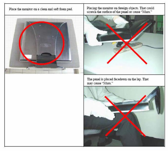
Handling and Placing Methods
ViewSonic Corporation |
Confidential - Do Not Copy |
VA702-2_VA721-3_VA721b-3 |
2
ViewSonic Corporation |
Confidential - Do Not Copy |
VA702-2_VA721-3_VA721b-3 |
3

2. Specification
1. INTPRODUCTION
|
FEATURES |
|
VA702-2 |
|
|
|
|
|
Size |
|
17 “ |
|
|
|
|
|
Luminance (Typ) |
|
300 cd/ |
|
|
|
|
|
Contrast Ratio (Typ) |
|
500:1 |
TFTLCD PANEL |
|
|
|
Colors (6 bits + 2 bits FRC) |
|
16.2 M |
|
|
|
|
|
|
Response Time (Typ) |
|
8 ms |
|
|
|
|
|
Viewing Angle (H/V) |
|
140 ° / 130 ° |
|
|
|
|
|
Recommend resolution |
|
1280x1024@60Hz |
|
|
|
|
Input Signal |
Analog (75ohms, 0.7/1.0 Vp-p) |
|
Yes |
|
|
|
|
Digital |
|
No |
|
|
|
||
|
|
|
|
|
Separate Sync |
|
Yes |
Sync Compatibility |
|
|
|
Composite Sync |
|
No |
|
|
|
|
|
|
Sync on Green |
|
No |
|
|
|
|
|
PC |
|
Yes |
Compatibility |
|
|
|
Power Mac |
|
Yes |
|
|
|
|
|
|
TV Box (NextVision 6) |
|
Yes |
|
|
|
|
Power Voltage |
AC 100-240V, 50/60Hz |
|
Yes |
|
|
|
|
Power |
On Mode(Max / Typ) |
|
36 W |
|
|
|
|
Consumption |
Off Mode (Max) |
|
1 W |
|
|
|
|
Audio |
|
|
No |
|
|
|
|
|
Tilt ( 20 ° - -5 °) |
|
Yes |
|
|
|
|
Ergonomics |
Swivel |
|
No |
|
|
|
|
Pivot |
|
No |
|
|
|
||
|
|
|
|
|
Height Adjust |
|
No |
|
|
|
|
OSD Control |
[ 1 ] [▼] [▲] [ 2 ] [ ] |
|
Yes |
|
|
|
|
Dimension |
Physical (W x H x D) |
|
378 x 374 x 196 mm |
|
|
|
|
Package (W x H x D) |
|
440 x 511 x 132 mm |
|
|
|
||
|
|
|
|
Weight |
Physical (Net Weight) |
|
4.5 kg |
|
|
|
|
Package (Gross Weight) |
|
6.2 kg |
|
|
|
||
|
|
|
|
Operating |
Temperature ( / ) |
|
32 -104 / 0 -40 |
Condition |
|
|
|
Humidity (%) |
|
10 % - 90 % |
|
|
|
|
|
Storage Condition |
Temperature ( / ) |
|
-4 -140 / -20 -60 |
|
|
|
|
Humidity (%) |
|
5 % - 90 % |
|
|
|
||
|
|
|
|
|
UL, cUL, FCC-B, CB, CE, ENERGY, NOM, TUV/GS, TUV ERGO |
||
|
(covers ISO13406-2 & MPRII), TCO’99 (VA702b), TCO’03 |
||
Regulation |
(VA702), GOST-R+20 ORIGINAL |
COPIES HYGIENIC, SASO, |
|
|
PCBC, VCCI, BSMI, CCC, (PSB), (C-TICK), TUV-S, Green Mark, |
||
|
Energy Star |
|
|
|
|
|
|
ViewSonic Corporation |
Confidential - Do Not Copy |
VA702-2_VA721-3_VA721b-3 |
4

|
|
FEATURES |
|
|
VA721-3 / VA721b-3 |
||
|
|
Size |
|
|
17 “ |
||
|
|
Luminance (Typ) |
|
|
300 cd/ |
||
|
|
|
|
|
|
|
|
|
TFTLCD PANEL |
Contrast Ratio (Typ) |
|
|
500:1 |
|
|
|
Colors (6 bits + 2 bits FRC) |
|
16.2 M |
||||
|
|
Response Time (Typ) |
|
8 ms |
|||
|
|
Viewing Angle (H/V) |
|
|
150 ° / 135 ° |
|
|
|
|
Recommend resolution |
|
1280x1024@60Hz |
|||
|
Input Signal |
Analog (75ohms, 0.7/1.0 Vp-p) |
|
Yes |
|||
|
Digital |
|
|
No |
|||
|
|
|
|
||||
|
Sync Compatibility |
Separate Sync |
|
|
Yes |
||
|
Composite Sync |
|
|
No |
|||
|
|
Sync on Green |
|
|
No |
||
|
Compatibility |
PC |
|
|
Yes |
||
|
Power Mac |
|
|
Yes |
|||
|
|
TV Box (NextVision 6) |
|
Yes |
|||
|
Power Voltage |
AC 100-240V, 50/60Hz |
|
Yes |
|||
|
Power |
On Mode(Max / Typ) |
|
|
35 W (Max) |
||
|
Consumption |
Off Mode (Max) |
|
|
1 W |
||
|
Audio |
|
|
|
|
No |
|
|
|
Tilt ( 20 ° -5 °) |
|
|
Yes |
||
|
Ergonomics |
Swivel |
|
|
No |
||
|
Pivot |
|
|
No |
|||
|
|
|
|
||||
|
|
Height Adjust |
|
|
No |
||
|
OSD Control |
[ 1 ] [▼] [▲] [ 2 ] [ ] |
|
|
Yes |
||
|
Dimension |
Physical (W x H x D) |
|
378 x 374 x 196 mm |
|||
|
Package (W x H x D) |
|
440 x 511 x 132 mm |
||||
|
|
|
|||||
|
Weight |
Physical (Net Weight) |
|
4.5 kg |
|||
|
Package (Gross Weight) |
|
6.2 kg |
||||
|
|
|
|||||
|
Operating |
Temperature ( / ) |
|
|
32 -104 / 0 -40 |
||
|
Condition |
Humidity (%) |
|
|
10 % - 90 % |
|
|
|
Storage Condition |
Temperature ( / ) |
|
|
-4 -140 / -20 -60 |
||
|
Humidity (%) |
|
|
5 % - 90 % |
|
||
|
|
|
|
|
|||
|
|
UL/cUL, FCC-B, CB, CE, ENERGY, NOM, TUV/GS, TUV ERGO |
|||||
|
Regulation |
(covers ISO13406-2 & MPRII), TCO’03, GOST-R+20 ORIGINAL |
|||||
|
COPIES HYGIENIC, SASO, PCBC, VCCI, BSMI, CCC, (PSB), |
||||||
|
|
||||||
|
|
(C-TICK), TUV-S, Green Mark, Energy Star |
|||||
2 GENERAL specification |
|
|
|
|
|
|
|
|
Test Resolution & Frequency |
|
1280x1024 @ 60Hz |
|
|
||
|
|
|
|
|
|
|
|
|
Test Image Size |
|
|
Full Size |
|
|
|
|
|
|
|
|
|
|
|
|
Contrast and Brightness Controls |
|
Factory Default: |
|
|
||
|
|
Contrast = 70%, Brightness = 100% |
|
||||
|
|
|
|
|
|||
|
|
|
|
|
|
|
|
ViewSonic Corporation |
Confidential - Do Not Copy |
VA702-2_VA721-3_VA721b-3 |
5
3 |
|
VIDEO INTERFACE |
|
|
|
|
|
|
Analog Input Connector |
|
DB-15 (Analog), refer the appendix A |
|
|
|
|
Video Cable Strain Relief |
|
Equal to twice the weight of the monitor for five |
|
|
|
|
|
minutes |
|
|
|
|
|
|
|
|
|
|
|
|
Video Cable Connector DB-15 Pin out |
|
Compliant DDC 1/2B |
|
|
|
|
Video Signals |
|
Video RGB (Analog) - Separate |
|
|
|
|
Video Impedance |
|
75 Ohms (Analog) |
|
|
|
|
Maximum PC Video Signal |
|
950 mV with no damage to monitor |
|
|
|
|
Maximum Mac Video Signal |
|
1250 mV with no damage to monitor |
|
|
|
|
Sync Signals |
|
LVDS |
|
|
|
|
DDC 1/2B |
|
Compliant with Revision 1.3 |
|
|
|
|
Sync Compatibility |
|
Separate Sync |
|
|
|
|
Video Compatibility |
|
Shall be compatible with all PC type |
computers, |
|
|
|
|
Macintosh computers, and after market |
video cards |
|
|
|
|
|
|
|
||
|
|
|
|
640 x 350, 640 x 480, 720 x 400 (640 x 400*), 800 x |
|
|
|
|
Resolution Compatibility |
|
600, 832 x 624, 1024 x 768, 1152 x 870, 1280 x 720, |
|
|
|
|
|
|
1280 x 1024 |
|
|
|
|
Exclusions |
|
Not compatible with interlaced video |
|
|
4 |
|
POWER SUPPLY |
|
|
|
|
|
|
Internal Power Supply |
|
Part Number: ILIPI-004 |
|
|
|
|
Input Voltage Range |
|
90 to 264 VAC |
|
|
|
|
Input Frequency Range |
|
47.5 to 63 Hertz |
|
|
|
|
Short Circuit Protection |
|
OUTPUT CAN BE SHORTED WITHOUT |
|
|
|
|
|
DAMAGE |
|
|
|
|
|
|
|
|
|
|
|
|
Over Current Protection |
|
2.4 A TYPICAL AT 14.2 VDC |
|
|
|
|
Leakage Current |
|
3.5MA (MAX) AT 254VAC / 60HZ |
|
|
|
|
Efficiency |
|
80% TYPICAL AT 115VAC FULL LOAD |
|
|
|
|
Fuse |
|
INTERNAL AND NOT USER |
|
|
|
|
|
REPLACEABLE |
|
|
|
|
|
|
|
|
|
|
|
|
Power Dissipation |
|
35 WATTS (TYP) |
|
|
|
|
Max Input AC Current |
|
0.8 ARMS @ 90VAC, 0.4 ARMS @265VAC |
|
|
|
|
Inrush Current (Cold Start) |
|
30 A @ 120VAC, 50 A (MAX) @ 220VAC |
|
|
|
|
|
|
Shall start and function properly when under |
|
|
|
|
Power Supply Cold Start |
|
full load, with all combinations of input |
|
|
|
|
|
voltage, input frequency, and operating |
|
||
|
|
|
|
|
||
|
|
|
|
temperature |
|
|
|
|
|
|
Shall be able to withstand an ansi/ieee |
|
|
|
|
Power Supply Transient Immunity |
|
c62.41-1980 2000v 200 ampere ring wave |
|
|
|
|
|
|
transient test with no damage |
|
|
|
|
Power Supply Line Surge Immunity |
|
Shall be able to withstand 1.5 times nominal |
|
|
|
|
|
line voltage for one cycle with no damage |
|
||
|
|
|
|
|
||
|
|
|
|
Shall be able to function properly, without |
|
|
|
|
Power Supply Missing Cycle Immunity |
|
reset or visible screen artifacts, when ½ |
|
|
|
|
|
cycle of AC power is randomly missing at |
|
||
|
|
|
|
|
||
|
|
|
|
nominal input |
|
|
|
|
Power Supply Acoustics |
|
The power supply shall not produce audible |
|
|
|
|
|
noise that would be detectable by the user. |
|
||
|
|
|
|
|
||
ViewSonic Corporation |
Confidential - Do Not Copy |
VA702-2_VA721-3_VA721b-3 |
6

|
|
|
Audible shall be defined to be in compliance |
|
|||||
|
|
|
with ISO 7779 (DIN EN27779:1991) Noise |
|
|||||
|
|
|
measurements of machines acoustics. |
|
|||||
|
|
|
Power Switch noise shall not be considered |
|
|||||
|
|
|
Separate 3-prong NEMA 5-15P type plug. |
|
|||||
|
US Type Power Cable |
Length = 1.8m. Connects to display. |
|
||||||
|
|
|
Color = Black |
|
|
|
|||
|
|
|
Schuko CEE7-7 type plug. |
|
|
|
|||
|
European Type Power Cable |
Length = 1.8m, Connects to display. |
|
||||||
|
|
|
Color = Black |
|
|
|
|||
|
|
|
|
|
|
|
|
||
|
|
|
Separate 3-prong type plug. |
|
|
|
|||
|
CCC Type Power Cable |
Length = 1.8m. Connects to display. |
|
||||||
|
|
|
Color = Black |
|
|
|
|||
|
|
|
|
|
|
|
|||
|
|
|
Separate 2-prong NEMA 1-15P type plug. |
|
|||||
|
PSE Type Power Cable |
Length = 1.8m. Connects to display. |
|
||||||
|
|
|
Color = Black |
|
|
|
|||
|
|
|
|
|
|
|
|
||
|
Power Saving Operation(Method) |
VESA DPMS Signaling |
|
|
|
||||
|
|
|
|
|
|
|
|
||
|
Power Consumption |
On Mode < 36 W (max) |
|
|
|
||||
|
Off Mode< 1W |
|
|
|
|||||
|
|
|
|
|
|
||||
|
|
|
|
|
|
|
|||
|
Recovery Time |
On Mode = N/A, Active Off < 3 sec |
|
||||||
|
|
|
|
|
|
|
|
|
|
5 ELECTRICAL REQUIREMENT |
|
|
|
|
|
|
|
||
Horizontal / Vertical Frequency |
|
|
|
|
|
|
|
||
|
|
|
|
|
|
|
|
||
|
Horizontal Frequency |
30 – 82 kHz |
|
|
|
||||
|
Vertical Refresh Rate |
50 – 85* Hz. |
|
|
|
||||
|
|
|
* When the resolution is set to 1280 x 1024, the vertical refresh |
|
|||||
|
|
|
rate may be up to 75 Hz; for all other resolutions, the vertical |
|
|||||
|
|
|
refresh rate may be up to 85Hz. |
|
|
|
|||
|
Maximum Pixel Clock |
140 MHz |
|
|
|
||||
|
Sync Polarity |
Independent of sync polarity. |
|
||||||
Timing Table |
|
|
|
|
|
|
|
||
|
|
|
|
|
|
|
|
|
|
|
Item |
Timing |
|
|
Analog |
|
|
|
|
|
1 |
640 x 350 @ 70Hz, 31.5kHz |
|
|
Yes |
|
|
|
|
|
2 |
640 x 400 @ 60Hz, 31.5kHz |
|
|
Yes |
|
|
|
|
|
3 |
640 x 400 @ 70Hz, 31.5kHz |
|
|
Yes |
|
|
|
|
|
4 |
640 x 480 @ 50Hz, 24.7kHz |
|
|
Yes |
|
|
|
|
|
5 |
640 x 480 @ 60Hz, 31.5kHz |
|
|
Yes |
|
|
|
|
|
6 |
640 x 480 @ 67Hz, 35.0kHz |
|
|
Yes |
|
|
|
|
|
7 |
640 x 480 @ 72Hz, 37.9kHz |
|
|
Yes |
|
|
|
|
|
8 |
640 x 480 @ 75Hz, 37.5kHz |
|
|
Yes |
|
|
|
|
|
9 |
640 x 480 @ 85Hz, 43.27kHz |
|
|
Yes |
|
|
|
|
|
10 |
720 x 400 @ 70Hz, 31.5kHz |
|
|
Yes |
|
|
|
|
|
11 |
800 x 600 @ 56Hz, 35.1kHz |
|
|
Yes |
|
|
|
|
|
12 |
800 x 600 @ 60Hz, 37.9kHz |
|
|
Yes |
|
|
|
|
|
13 |
800 x 600 @ 75Hz, 46.9kHz |
|
|
Yes |
|
|
|
|
|
14 |
800 x 600 @ 72Hz, 48.1kHz |
|
|
Yes |
|
|
|
|
|
15 |
800 x 600 @ 85Hz, 53.7kHz |
|
|
Yes |
|
|
|
|
|
16 |
832 x 624 @ 75Hz, 49.7kHz |
|
|
Yes |
|
|
|
|
|
17 |
1024 x 768 @ 60Hz, 48.4kHz |
|
|
Yes |
|
|
|
|
|
18 |
1024 x 768 @ 70Hz, 56.5kHz |
|
|
Yes |
|
|
|
|
|
19 |
1024 x 768 @ 72Hz, 58.1kHz |
|
|
Yes |
|
|
|
|
ViewSonic Corporation |
|
|
|
|
VA702-2_VA721-3_VA721b-3 |
||||
|
Confidential - Do Not Copy |
|
|||||||
7
20 |
1024 x 768 |
@ 75Hz, 60.0kHz |
Yes |
|
21 |
1024 x 768 |
@ 85Hz, 68.67kHz |
Yes |
|
22 |
1152 x 870 @ 75Hz, 68.7kHz |
Yes |
||
23 |
1280 x 1024 |
@ 60Hz, 63.4kHz |
Yes |
|
24 |
1280 x 1024 |
@ 75Hz, 79.97kHz |
Yes |
|
25 |
1280x 720 @ 60Hz, 45kHz (HDTV) |
Yes |
||
Primary Presets
1280x1024 @ 60Hz
User Presets
Number of User Presets (recognized timings) Available: 10 presets total in FIFO configuration
Changing Modes
●Maximum Mode Change Blank Time for image stability: 3 seconds (Max), excluding “Auto Image Adjust” time.
●Under DOS mode (640 x 350, 720 x 400 & 640 x 400), it should recall factory setting when
execute “Auto Image Adjust”.
The monitor needs to do “Auto Image Adjust” the first time when a new mode is detected. (See section “0-Touch™ Function Actions”)
6 FRONT PANEL CONTROLS AND INDICATORS
Front Panel Hardware Controls
|
Power Switch (Front Head) |
|
Power Control, soft Power Switch. |
|
|||
|
|
|
|
|
|
||
|
Power LED (Front Head) |
|
Green – ON |
|
|
||
|
|
|
Orange – Active Off |
|
|
||
|
|
|
Dark = Soft Power Switch OFF |
|
|||
|
|
|
|
|
|
||
|
Front Panel Controls (Head) |
|
[ ] Power |
|
|
||
|
[ ] [ 1 ] [ 2 ] [▲] [▼] |
|
[ 1 ] BUTTON 1 |
|
|
||
|
|
|
[ 2 ] Button 2 |
|
|
||
|
|
|
[▲] UP ARROW BUTTON |
|
|
||
|
|
|
[▼] DOWN ARROW BUTTON |
|
|||
|
|
|
Note: Power Button, Button 1 and Button 2 |
|
|||
|
|
|
must be one-shot logic operation. (i.e. there |
|
|||
|
|
|
should be no cycling) |
|
|
||
|
|
|
|
|
|||
|
Reaction Time |
|
OSD must fully appear within 0.5s after |
|
|||
|
|
|
pushing Button 1 |
|
|
||
|
|
|
|
|
|
||
Short Cuts Function from the button(s) |
|
|
|||||
|
|
|
|
||||
|
[1] |
Main Menu |
|
|
|||
|
|
|
|
|
|||
|
[2] |
Auto Image Adjust |
|
|
|||
|
|
|
|
||||
|
[▼] or [▲] |
To immediately activate Contrast menu. It should be |
|
||||
|
|
change to Brightness OSD by push button [2] |
|
||||
|
|
|
|
||||
|
[▼]+ [▲] |
Recall both of Contrast and Brightness to default |
|
||||
|
|
|
|
||||
|
[1] + [2] |
Toggle 720x400 and 640x400 mode when input 720x400 |
|
||||
|
|
or 640x400 mode |
|
|
|||
|
|
|
|
|
|
|
|
ViewSonic Corporation |
|
|
|
|
VA702-2_VA721-3_VA721b-3 |
||
|
|
Confidential - Do Not Copy |
|
||||
8
[1] + [▼] + [▲] |
White Balance. (Not shown on user’s guide) |
|
|
[1] + [▼] |
Power Lock |
|
|
[1] + [▲] |
OSD Lock |
|
|
Remark : All the short cuts function are only available while OSD off
Main Menu Controls
Auto Image Adjust
Contrast/Brightness*1*3
Color Adjust
SRGB, 9300K, 6500K(default), 5400, User Color [R, G, B]
Information [H Frequency, V Frequency, Pixel Clock, Resolution, Serial Number, Model Number, “www.ViewSonic.com” ]
Manual Image Adjust [H. Size, H. Position, V. Position, Fine Tune, Sharpness*2
Setup Menu
Language [English, French, German, Italian, Spanish, Finnish, Japanese, Traditional Chinese, Simplified Chinese]
Resolution Notice, OSD Position, OSD Timeout, OSD Background
Memory Recall
*1 These functions are not available under SRGB Mode
*2 These functions are not available under Native Resolution Mode
*3 These function settings can be set to default value by pressing [▼]+[▲]
[Remark] Please refer to the detail in the Appendix C
Function descriptions
OSD Lock short cuts function for the buttons
The OSD lock will be activated by pressing the front panel control buttons "(1), & (▲)" for 10 seconds. If the user then tries to access the OSD by pressing any of the buttons "1", "▼", "▲", "2" a message will appear on the screen for 3 seconds showing "OSD Locked". The OSD lock will be deactivated by pressing the front panel control buttons "(1), & (▲)" again for 10 seconds.
Note1: When the OSD is locked will lock all functions, including “Volume” and “Mute” Note 2: Status bar indicating OSD Lock or Unlock is in progress and when complete it will indicate “OSD Locked”
Note 3: OSD Lock should not lock Power Button and Power Lock function
ViewSonic Corporation |
Confidential - Do Not Copy |
VA702-2_VA721-3_VA721b-3 |
9

Power Lock short cuts function for the buttons
The power button lock will be activated by pressing the front panel control buttons "(1), & (▼)" for 10 seconds. Locking the power button means that the user won't be able to turn off the LCD while the power button is locked. If the user presses the power button while it is locked, a message will appear on the screen for 3 seconds showing "Power Button Locked". It also means that with the power button locked, the LCD would automatically turn back "On" when power is restored after a power failure. If the power button is not in the locked mode, then power should return to its previous state when power is restored after a power failure. The power button lock will be deactivated by pressing the front panel control buttons "(1), & (▼)" again for 10 seconds.
Note 1: Status bar indicating Power Button lock or unlock is in progress and when complete it will indicate “Power Button Locked”
Note 2: Power should only be lockable in the “On State”
Memory Recall Actions
Memory Recall action on the analog and digital mode as below
1.Recall white balance to factory setting
2.Set the factory defaults as shown in Section 4-8
3.Clean all the mode setting buffer
4.Execute Auto Image Adjust
Note: Memory Recall cannot effect at Language, Power Lock and User Color Settings
Resolution Notice Actions
1.Resolution Notice OSD should show on screen after changing to non-native mode for 30 sec
2.The OSD should disappear after 10 sec or by pushing button [1] or [2]
Resolution Notice function should be disabled when push button [2] under Resolution Notice OSD
0-Touch™ Function Actions
1.Execute Auto Image Adjust when new mode detected, and save the settings to buffer for further use
2.It should be reset by Memory Recall function
(Should not reset by power off, power unplug and others)
OSD Auto Save
The OSD shall save new settings when it is turned off by the user or when it times out. There shall not be a separate save
ViewSonic Corporation |
|
Confidential - Do Not Copy |
VA702-2_VA721-3_VA721b-3 |
|
10 |
|
|

3. Front Panel Function Control Description
1. |
Key Function Description |
|
|||
|
|
CONTROL KEY |
|
KEYS FUNCTION |
|
|
|
|
|
|
|
|
|
[AUTO] [2] |
|
By pressing [AUTO] key, “Auto Image Adjust” is performed |
|
|
|
|
|
|
|
|
|
[MENU] [1] |
|
By pressing [MENU] key, Main menu display |
|
|
|
|
|
|
|
|
|
|
|
A. When “MENU OSD” display, press these keys to change the contents of |
|
|
|
[▼] [▲] |
|
an adjustment item, or change an adjustment value |
|
|
|
|
B. When “MENU OSD” is un-display, press these keys to change brightness |
|
|
|
|
|
|
|
|
|
|
|
|
and contrast |
|
|
|
|
|
|
|
|
|
[POWER] |
|
Power on or power off the monitor |
|
|
|
|
|
|
|
2. |
Hot Key Operation |
|
|
|
|
|
|
|
|
|
|
|
|
CONTROL KEY |
KEYS FUNCTION |
|
|
|
|
|
|
|
|
|
|
[▼] + [▲] |
Recall Contrast or Brightness while in the Contrast or Brightness adjustment, |
|
|
|
|
or recall both of Contrast and Brightness when the OSD is not open. |
|
||
|
|
|
|
||
|
|
|
|
|
|
|
[1] + [2] |
Toggle 720x400 and 640x400 mode when input 720x400 or 640x400 mode. |
|
||
|
|
|
|
|
|
|
|
[1] + [▼] + [▲] |
White Balance (Not shown on user’s guide) |
|
|
|
|
|
|
|
|
|
|
[1] + [▼] |
Power Lock |
|
|
|
|
|
|
|
|
|
|
[1] + [▲] |
OSD Lock |
|
|
|
|
|
|
|
|
Remark : All the short cuts function are only available while OSD off
3. OSD Control |
|
|
|
|
|
|
|
3.1 OSD table |
|
|
|
|
|
|
|
|
|
|
|
|
|
|
|
|
Layer 1 |
Layer 2 |
|
Layer 3 |
|
|
|
|
|
|
|
|
|
|
|
|
Auto Image Adjust |
|
|
|
|
|
|
|
Contrast/Brightness |
Contrast (+ / -) |
|
|
|
|
|
|
|
|
|
|
|
||
|
Brightness (+ / -) |
|
|
|
|
|
|
|
|
|
|
|
|
|
|
|
|
Srgb |
|
|
|
|
|
|
|
9300K |
|
|
|
|
|
|
|
|
|
|
|
|
|
|
|
6500K |
|
|
|
|
|
|
Color Adjust |
5400K |
|
|
|
|
|
|
|
|
|
Red (+ / -) |
|
|
|
|
|
User Color |
|
|
|
|
|
|
|
|
Green (+ / -) |
|
|
||
|
|
|
|
|
|
|
|
|
|
|
|
Blue (+ / -) |
|
|
|
|
|
|
|
|
|
|
|
|
Information |
|
|
|
|
|
|
|
Manual Image Adjust |
H/V Position |
|
H Position (+ / -) |
|
|
|
|
|
|
|
|
|
|
|
|
|
|
V Position (+ / -) |
|
|
||
|
|
|
|
|
|
||
|
|
|
|
|
|
|
|
ViewSonic Corporation |
|
|
|
|
VA702-2_VA721-3_VA721b-3 |
||
|
Confidential - Do Not Copy |
|
|||||
11
|
|
|
|
|
H Size |
+ / - |
|
|
|
|
|
|
|
|
|
|
|
|
|
|
Fine Tune |
+ / - |
|
|
|
|
|
|
|
|
|
|
|
|
|
|
Sharpness |
+ / - |
|
|
|
|
|
|
|
|
|
|
|
|
|
|
|
English |
|
|
|
|
|
|
|
|
|
|
|
|
|
|
|
French |
|
|
|
|
|
|
|
|
|
|
|
|
|
|
|
German |
|
|
|
|
|
|
|
|
|
|
|
|
|
|
|
Italian |
|
|
|
|
|
|
Language Select |
|
|
|
|
|
|
|
Spanish |
|
|
|
|
|
|
|
|
|
|
|
|
|
|
|
|
Finnish |
|
|
|
|
|
|
|
|
|
|
Setup Menu |
|
|
Japanese |
|
||
|
|
|
|
|
|||
|
|
|
Simplified Chinese |
|
|||
|
|
|
|
|
|
|
|
|
|
|
|
|
|
|
|
|
|
|
|
|
|
Traditional Chinese |
|
|
|
|
|
|
|
|
|
|
|
|
|
|
Resolution Notice |
On/Off |
|
|
|
|
|
|
|
|
|
|
|
|
|
|
OSD Position |
H Position (+ / -) |
|
|
|
|
|
|
|
|
|
|
|
|
|
|
V Position (+ / -) |
|
|
|
|
|
|
|
|
|
|
|
|
|
|
|
|
|
|
|
|
|
|
|
OSD Time Out |
|
|
|
|
|
|
|
OSD Background |
On/Off |
|
|
|
|
|
|
|
|
|
|
Memory Recall |
|
|
|
|
||
|
|
|
|
|
|
|
|
3.2 OSD lock Menu function |
|
|
|
|
|||
|
|
|
|
|
|
|
|
|
|
|
|
|
OSD Lock Menu Function Check |
||
|
|
|
|
|
|
||
|
|
Item |
|
Method |
Phenomenon |
||
|
|
|
|
|
|
|
|
|
|
|
|
|
|
Press any of buttons"1", "▼", |
|
|
|
Activate OSD lock |
|
[1] + [▲] 10S |
"▲", "2" will appear "OSD |
||
|
|
|
|
|
|
Locked" 3s |
|
|
|
|
|
|
|
|
|
|
|
Deactivate OSD lock: |
|
[1] + [▲] 10S(again) |
|
|
|
|
|
|
|
|
|
|
|
|
|
NOTICE: |
|
|
|
|
|
|
|
When the OSD is locked will lock all functions. |
|
|
|||
|
|
Status bar indicating OSD Lock or Unlock is in progress and when complete it will indicate |
|||||
|
|
“OSD Locked” |
|
|
|
|
|
|
|
OSD Lock should not lock Power Button and Power Lock function |
|||||
|
|
|
|
|
|
|
|
ViewSonic Corporation |
Confidential - Do Not Copy |
VA702-2_VA721-3_VA721b-3 |
12
3.3 Power lock Menu function
|
|
Power Lock Menu Function Check |
|
|
|
|
|
|
Item |
Method |
Phenomenon |
|
|
|
|
|
Activate Power Lock |
|
Can not turn off the LCD; |
|
|
|
Press the power button will |
|
|
|
appear "Power Button Locked" |
|
|
[1] + [▼] 10S |
OSD 3s; |
|
|
|
LCD would automatically turn |
|
|
|
back "On" when power is |
|
|
|
restored after a power failure |
|
|
|
|
|
Deactivate Power |
[1] + [▼] 10S(again) |
|
|
Lock |
|
|
|
|
|
|
|
|
|
|
|
NOTICE: |
|
|
|
Status bar indicating Power Button lock or unlock is in progress and when complete it will |
||
|
indicate “Power Button Locked” |
|
|
|
Power should only be lockable in the “On State” |
|
|
|
|
|
|
3.4 Resolution notice function |
|
|
|
|
|
|
|
|
|
Resolution Notice Menu |
|
|
|
|
|
|
Item |
Method |
Phenomenon |
|
|
|
|
|
|
Resolution Notice OSD should |
|
|
Activate Resolution |
show on screen after changing |
|
|
to non-native mode for 30 sec, |
------ |
|
|
Notice Menu |
||
|
And it should disappear after 10s |
|
|
|
|
|
|
|
|
or by pushing button [1] or [2] |
|
|
|
|
|
|
Deactivate |
Push button [2] under Resolution |
|
|
Resolution Notice |
------- |
|
|
Notice OSD, select Disable |
||
|
Menu |
|
|
|
|
|
|
|
|
|
|
3.5 Factory Mode Introduction
When input the signal, press “power key” to turn off the monitor. Press” [▼] +[▲] +[ ] “at the same time so as to enter factory mode. After power on, press ‘’Menu[1]’’key, you can see the Factory menu.
INL : Currently using panel model name
V2 050526 |
: Currently using firmware version information. |
Auto Color |
: Automatically calibrate chip ADC parameter by using chip internal DAC |
Color Temperature : The R, G, B of 9300K and 6500K and 5400K and User Mode Colors are all generated from scaling back end.
ViewSonic Corporation |
Confidential - Do Not Copy |
VA702-2_VA721-3_VA721b-3 |
13
4. Circuit Description
4.1 Switching Mode Power Supply
4.1.1 AC Current Input Circuit
P801 is a connector for connecting AC Power. F801 is a fuse to protect all the circuit. AC input voltage is from 90V to 264V. R820 and R821 joined between two inputting main circuit to prevent man from shock. L801 is used to clear up low frequency wave. C801 and C806 are used to discharge the waves that L801 produced. High frequency waves are damped by C801 and C806. D801 is a rectifier which composed of 4 build-in diodes, it inverts AC to DC.
4.1.2High Voltage to Low Voltage Control Circuit
C805 is used to smooth the wave from rectifier. IC802 is a highly integrated PWM controller, which build-in a power MOSFET. When rectified DC high voltage is applied to the DRAIN pin during start-up, the MOSFET is off initially, and the CONTROL pin capacitor is charged through a switched high voltage current source connected internally between the DRAIN and CONTROL pins. When the CONTROL pin voltage Vc reaches approximately 5.8V, the control circuitry is activated and the soft-start begins. The soft-start circuit gradually increases the duty cycle of the MOSFET from zero to the maximum value over approximately 10ms. If no external feedback/supply current is fed into the CONTROL pin by the end of the soft-start, the high voltage current source is turned off and the CONTROL pin will start discharging in response to the supply current drawn by the control circuitry.
Resistor R803, R807, R824 and R825 are for line over voltage shut-down (OVP) and line under-voltage detection (UVP).Resistors R801, R805, R822, and R823 are for external current limit adjustment, and used to reduce the current limit externally to a value close to the operating peak current of primary about 1.35A. The mean is power will protected when the primary current over about 1.35A.
When PWM is turned off, the main current flow will be consumed through D804 and ZD802, This will prevent MOSFET which built-in IC802 from being damaged under large current impulse and voltage spike.
D806 and C815 provide internal Auxiliary current to CONTROL pin during normal operation. In addition, error amplifier and feedback current to the CONTROL pin are for duty cycle control.
4.1.3DC_5V and DC_14V Output Circuit
For DC 5V, D805 is used to rectify the inducted current. R806 and C811 are used to store energy when current is reversed. The parts including C812, C814, C822, C821, B801 and L803 are used to smooth the current waves.
For DC 14V, D803 is used to rectify the inducted current. R802 and C802 are used to store energy when current is reversed. The parts including C808, C810 and L802 are used to smooth the current waves.
4.1.4Feedback and OVP Protect Circuit
Pin R of IC803 is supplied 2.5V stable voltage. It is connected to 5V and 14V output through R811, R810 and R818. R811, R810 and R818 are output sampling resistor. When the sampling voltage more than 2.5V or less than 2.5V, feedback current of IC802 will change, this can change the voltage from transformer T801.
For 5VDC output OVP, ZD803 is a zener diode, when 5V output voltage becomes up to 5.6V, the
ViewSonic Corporation |
Confidential - Do Not Copy |
VA702-2_VA721-3_VA721b-3 |
14
zener current cause R819 voltage become up to 0.7V, Q801 is triggered and OVP starts. For 12VDC output OVP, ZD804 is a Zener Diode, when 14V output voltage becomes up to 16V, the zener current cause R819 voltage become up to 0.7V, Q801 is triggered and OVP starts. The collector current of Q801 is used to make build-in diode light. FB Current of IC802 will be changed; it can change the voltage from T801.
Q802, R827, R828 and ZD801 make up of dummy loading circuit. For start-up sequence, during 5V output take place high loading first, this dummy loading circuit operated to insure 14V not be increased.
4. 2 Inverter circuit
4.2.1Low voltage to high voltage circuit
12VDC supplies the power to IC501 through F501; the control signals that BRIGHTNESS and ON/OFF come from I/F board. ON/OFF signal connect to pin8 of IC501 and makes IC501 enabled. BRIGHTNESS is connected to pin7 of IC501 to adjust the panel luminance. R524, R529, C505 make up of a delay-time circuit and R528, R523, R524 make up of a voltage divided circuit. C504 is used to filter the high frequency noise. The operation frequency is determined by R522 and C529. For BURST MODE, its dimming frequency is determined by R527 and C506. C502 is used for soft start and compensation, C502, C528 are used to filter noise.
The output drives, including NDR4, NDRV2, PDRV3, PDRV1 (pins1, 3, 15, 16 respectively), generate a square pulses to drive MOSFET U501, U502. And U501, U502 works as full-bridge topology, it is high efficient, zero voltage switch.
During start up, VSEN (pin9) detects the voltage at the transformer secondary. When VSEN reaches 3.0V, the output voltage is regulated. If no current is detected for around 1.5 seconds, IC501 will shut down.
The current flowing through CCFL is detected and regulated through sense resistor R509, R511. The feedback voltage through R506, R507, and C508 connected to Pin11 (ISEN), and then compared with a reference voltage (1.5V) via a current amplifier, resulting in PWM drive outputs to full-bridge switches.
4.2.2Protection circuit
Over Voltage Protection: R501and R502 are connected in high voltage output connector, the divided AC voltage is inverted DC voltage through D508, R505 and C507are used to rectify wave & dump noise. Then the voltage signal reaches Pin9 VSEN of IC501, when the voltage changes, build-in PWM of IC501 will adjust output voltage.
Open Lamp Protection: In normal operation, the resistors R510, R511, R512, R509 are sensed a high level AC voltage, the AC signal IS1 invert DC voltage through D509, R515, C533, and the high level DC voltage reaches the gate pin of Q502, similarly, the gate pin of Q503, Q504, Q505 has high level DC voltage. So the gate pin of Q501 has a low level voltage, and the IC501 is normal operation. Once one of signal IS1, IS2, IS3, and IS4 is low, the voltages of Q501 gate pin is high level, and make the voltage of ISEN low level, the IC501 will shut down.
4.3I/F Board Circuit
4.3.1Power Input
ViewSonic Corporation |
Confidential - Do Not Copy |
VA702-2_VA721-3_VA721b-3 |
15
+5V is from the power board and supply for U101(FS8860-18PJ) U102(FS8860-33PJ) U105(MCU:W78E65P) and panel. +3.3V output is generated from +5V through C169 and C102 filtering, and U102 outputs. +3.3V is used for U104 (Scaler: TSU16AK). +1.8V output is generated from +5V through C169, C105 and C102 filtering, and U101 outputs. +1.8V is also used for U104. 4.3.2MCU (W78E65P)
VDD is +5V and its frequency of XTAL1 is 22.1184MHz. U105 #2 is defined as panel-enable. When the I/O port is low, Q101 and Q102 are conducted. And then after C109 and C110 filtering, obtain the voltage of VLCD, which will be connected to CN103. U105 #3 is defined as CCFL-enable. When the I/O port is low, Q103 is pulled up and the backlights are on; When the I/O port is high, Q103 is conducted and the backlights are off. U105 #4 is defined as DET-VGA, connected with CN102 #5. U105 #14, #36, #37, #38, #39, #40, #41, #42, #43 are the communications with U104 (Scaler), which are connected to #72, #31, #78, #77, #30, #70, #71, #69, #32 of Scaler. U105 #43 outputs reset signal to U104 (Scaler).
U106 is EEPROM used for saving EDID data, which is connected by SCL and SDA pins with #16 and #17 of MCU. Connect #12 to #26 of U105 for ISP.
4.3.3Scaler (TSU16AK)
The frequency of XTAL2 is 14.318MHz. U104 #1, #102-#103, #106-#113, #118-#125, #128 output LVDS digital data of 8 bit to panel control circuit through CN103. U104 #73 generates a PWM waveform by regulating the duty to control the brightness of the backlights. U104 #30-#32, #69-#72, #77-#78 are the communications with U105 (MCU) that are connected to #36-#43 of MCU. These communications include HWRESET, CSZ/ALE, SCL/RDZ, SDA/WRZ, and AD0-AD3.
4.3.4VGA Input
Signal R, G, B, SOG input through CN102 #1, #2, #3, and C115, C116, C117 and C118 filtering the high frequency noise. Signal HSYNC and VSYNC input through CN102 #13 and #14, and C119, R119, C120, R120 filtering. Then the analog signal enters U104, and then U104 deals with it internally. In addition, TVS101, TVS102, TVS103 (the three are BAV99), TVS104, TVS105, TVS106, TVS107 (they are constant voltage diode of 5V6) are ESD protector. Signal DDC-SCL inputs via CN102 #15, and then passes through TVS107 for ESD protection, goes into EDID EEPROM IC U103. Signal DDC-SDA inputs via CN102 #12, and then passes through TVS106 for ESD protection, goes into EDID EEPROM IC U103. CN102 #5 is defined as cable detect pin, this detector realizes via R107 and U105 #4. The PC-5V of U103 is supplied by PC via CN103 #9 with D103 for ESD protection, or supplied by Monitor self via D104.U103 is an EEPROM IC, which is a kind of memory and used for saving EDID data.
4.3.5Button Control
Button “Key-Power” is defined as power on/off, which is connected to U105 #24 through CN106 #4.
Button “Key-2” is defined as two functions of selecting and adjustment, which is connected to U105 #25 through CN106 #1.
Button “Key-Up” is defined as plus, which is connected to U105 #26 through CN106 #3. Button “Key-Down” is defined as minus, which is connected to U105 #27 through CN106 #5.
Button “Key-1” is defined as two functions of menu and exit, which is connected to U105 #28
ViewSonic Corporation |
Confidential - Do Not Copy |
VA702-2_VA721-3_VA721b-3 |
16
 Loading...