


Service Manual
ViewSonic VA712b-2
Model No VS10901
17” Color TFT LCD Display
Manufacture Date: Mar-30-06
- 1 –
ViewSonic Corporation
Copyright
Copyright © 2005 by ViewSonic® Corporation. All rights reserved. No part of this publication may be reproduced, transmitted, transcribed, stored in a retrieval system, or translated into any language or manual or otherwise, without the prior written permission of ViewSonic Corporation.
Disclaimer
ViewSonic® makes no representation or warranties, either expressed or implied, with respect to the contents hereof and specifically disclaims any warranty of merchantability of fitness for any particular purpose. Further, ViewSonic reserves the right to revise this publication and to make changes from time to time in the contents hereof without obligation of ViewSonic to notify any person of such revision or changes.
Trademarks
Optiquest is a registered trademark of ViewSonic Corporation.
ViewSonic® is a registered trademark of ViewSonic Corporation.
All other trademark used within this document are the property of their respective owners.
Revision History
Revision |
Date |
Description of changes |
Approval |
|
|
|
|
A00 |
Sep-9-05 |
Initial Release |
YG.WANG |
|
|
|
|
|
|
Update the Handing and Placing Methods |
|
A01 |
Mar-30-06 |
and the Circuit Description and the |
YG.WANG |
|
|
Adjustment Procedure |
|
|
|
|
|
|
|
|
|
|
|
|
|
|
|
|
|
|
|
|
|
|
|
|
|
- 2 –
ViewSonic Corporation

|
TABLE OF CONTENTS |
|
1. Precautions And Safety Notices |
4 |
|
2. |
Specification |
7 |
3. Front Panel Control And Indicators |
11 |
|
4. |
Circuit Description |
17 |
5. Adjusting Procedure |
27 |
|
6. Troubleshooting Flow Chart |
47 |
|
7. |
Recommended Spare Parts List |
48 |
8. |
Exploded Diagram And Spare Parts List |
66 |
9. |
Disassemble Process |
70 |
|
|
|
10. Block Diagram |
75 |
|
11. Schematic Diagram |
76 |
|
12. PCB Layout Diagram |
83 |
|
- 3 –
ViewSonic Corporation
1. Precautions And Safety Notices
1.1 SAFETY PRECAUTIONS
This monitor is manufactured and tested on a ground principle that a user’s safety comes first. However, improper use or installation may cause damage to the monitor as well as the user. Carefully go over the following WARNINGS before installing and keep this guide handy.
WARNINGS
This monitor should be operated only at the correct power sources indicated on the label on the rear end of the monitor. If you’re unsure of the power supply in your residence, consult you local dealer or power company.
Use only the special power adapter that comes with this monitor for power input.
Do not try to repair the monitor your self as it contains no user-serviceable parts. This monitor should only be repaired by a qualified technician.
Do not remove the monitor cabinet. There is high-voltage parts inside that may cause electric shock to human bodies, even when the power cord is unplugged.
Stop using the monitor if the cabinet is damaged. Have it checked by a service technician.Put your monitor only in a clean, dry environment. If it gets wet, unplug the power cable
immediately and consult your service technician.
Always unplug the monitor before cleaning it .Clean the cabinet with a clean, dry cloth. Apply non-ammonia based cleaner onto the cloth, not directly onto the glass screen.
Keep the monitor away from magnetic objects, motors, TV sets, and transformer.Do not place heavy objects on the monitor or power cord.
1.2PRODUCT SAFETY NOTICE
Many electrical and mechanical parts in this chassis have special safety visual inspections and the protection afforded by them cannot necessarily be obtained by using replacement components rated for higher voltages, wattage, etc. Before replacing any of these components read the parts list in this manual carefully. The use of substitute replacement parts which do not have the same safety characteristics as specified in the parts list may create shock, fire ,or other hazards.
1.3SERVICE NOTES
1.When replacing parts or circuit boards, clamp the lead wires around terminals before soldering.
2.When replacing a high wattage resistor(more than 1W of metal oxide film resistor) in circuit board, keep the resistor about 5mm away from circuit board.
3.Keep wires away from high voltage, high temperature components and sharp edges.
4.Keep wires in their original position so as to reduce interference.
5.Usage of this product please refer to also user’s manual.
- 4 –
ViewSonic Corporation

1.4HANDING AND PLACING METHODS
Correct Methods: |
Incorrect Methods: |
|
|
Only touch the metal frame of the LCD panel or the front cover of the monitor. Do not touch the surface of the polarizer.
Surface of the LCD panel is pressed by fingers and that may cause “Mura.”
Take out the monitor with cushions |
Taking out the monitor by grasping the LCD |
|
panel. That may cause “Mura.” |
||
|
- 5 –
ViewSonic Corporation
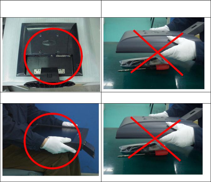
Place the monitor on a clean and soft foam pad.
Placing the monitor on foreign objects. That could scratch the surface of the panel or cause “Mura.”
Place the monitor on the lap, the panel |
The panel is placed facedown on the lap. That |
surface must be upwards. |
may cause “Mura.” |
- 6 –
ViewSonic Corporation
2.Specification
2.1PRODUCT SPECIFICATIONS
|
LCD Panel |
17.0” TFT |
|
|
|
|
Recommend Resolution |
1280 x1024@60Hz |
|
|
|
|
Pixel Dimension |
0.264(H) x 0.264(V)mm |
|
|
|
|
LCD Display Color |
16.2M Colors (RGB 6-bit+FRC data) |
|
|
|
|
Viewing Angle |
Horizontal: 140 ° |
|
Vertical: 130 ° |
|
|
|
|
|
|
|
|
Contrast Ratio |
500 1 (Typ.) |
|
|
|
|
Brightness |
300 cd/ (Typ.) |
|
|
|
|
Response Time |
8ms(Typ.) |
|
|
|
|
Active Display Area |
337.9mm(H) x 270.3mm(V) |
|
|
|
|
Maximum Pixel Clock |
135 MHz |
|
|
|
|
Horizontal Frequency |
30 – 82 kHz |
|
|
|
|
Vertical Refresh Rate |
50 – 85 Hz. |
|
|
|
|
Temperature |
Operating: 0°C to +40°C |
|
Storage: -20°C to +60°C |
|
|
|
|
|
|
|
|
Input Signal |
Analog / Digital |
|
|
|
|
|
Energy Star compliant VESA |
|
Power Management |
DPMS compatible |
|
|
1 W |
|
|
|
|
Power |
Input Voltage : 90V~264ACV 50~60Hz(auto switch) |
|
Consumption: 39 Watts(Max.) 36 Watts(Typ.) |
|
|
|
|
|
|
|
ViewSonic Corporation |
- 7 – |
|
|
||

2.2 FACTORY SUPPORTING MODES
Timing Table :
Item |
|
Timing |
Analog |
Digital |
|
|
|
|
|
1 |
640 x 350 |
@ 70Hz, 31.5kHz |
Yes |
Yes |
|
|
|
|
|
2 |
640 x 480 |
@ 60Hz, 31.5kHz |
Yes |
Yes |
|
|
|
|
|
3 |
640 x 480 |
@ 67Hz, 35.0kHz |
Yes |
Yes |
|
|
|
|
|
4 |
640 x 480 |
@ 72Hz, 37.9kHz |
Yes |
Yes |
|
|
|
|
|
5 |
640 x 480 |
@ 75Hz, 37.5kHz |
Yes |
Yes |
|
|
|
|
|
6 |
640 x 480 @ 85Hz, 43.27kHz |
Yes |
Yes |
|
|
|
|
|
|
7 |
720 x 400 |
@ 70Hz, 31.5kHz |
Yes |
Yes |
|
|
|
|
|
8 |
800 x 600 |
@ 56Hz, 35.1kHz |
Yes |
Yes |
|
|
|
|
|
9 |
800 x 600 |
@ 60Hz, 37.9kHz |
Yes |
Yes |
|
|
|
|
|
10 |
800 x 600 |
@ 72Hz, 48.1kHz |
Yes |
Yes |
|
|
|
|
|
11 |
800 x 600 |
@ 75Hz, 46.9kHz |
Yes |
Yes |
|
|
|
|
|
12 |
800 x 600 |
@ 85Hz, 53.7kHz |
Yes |
Yes |
|
|
|
|
|
13 |
832 x 624 |
@ 75Hz, 49.7kHz |
Yes |
Yes |
|
|
|
|
|
14 |
1024 x 768 @ 60Hz, 48.4kHz |
Yes |
Yes |
|
|
|
|
|
|
15 |
1024 x 768 @ 70Hz, 56.5kHz |
Yes |
Yes |
|
|
|
|
|
|
16 |
1024 x 768 @ 72Hz, 58.1kHz |
Yes |
Yes |
|
|
|
|
|
|
17 |
1024 x 768 @ 75Hz, 60.0kHz |
Yes |
Yes |
|
|
|
|
|
|
18 |
1024 x 768 |
@ 85Hz, 68.67kHz |
Yes |
Yes |
|
|
|
|
|
19 |
1152 x 870 @ 75Hz, 68.6kHz |
Yes |
Yes |
|
|
|
|
|
|
20 |
1280 x 1024 @ 60Hz, 63.4kHz |
Yes |
Yes |
|
|
|
|
|
|
21 |
1280 x 1024 @ 75Hz, 79.97kHz |
Yes |
Yes |
|
|
|
|
|
|
22 |
1280 x 720 @ 60Hz, 45kHz |
Yes |
Yes |
|
|
|
|
|
|
Primary Preset: VESA : 1280 x1024@60Hz
- 8 –
ViewSonic Corporation
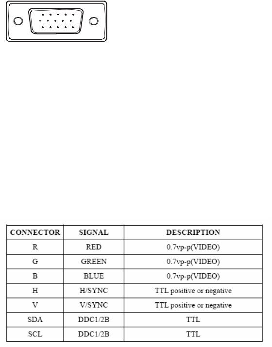
2.3 INTERFACE DESCRIPTION
D-SUB 15 PIN CONNECTOR
1 |
5 |
6 |
10 |
11 |
15 |
SIGNAL LEVEL
Pin Number |
Pin Function |
|
|
1 |
Red video input |
|
|
2 |
Green video input |
|
|
3 |
Blue video input |
|
|
4 |
No Connection |
|
|
5 |
Ground |
|
|
6 |
Red video ground |
|
|
7 |
Green video ground |
|
|
8 |
Blue video ground |
|
|
9 |
+5V |
|
|
10 |
H/V sync ground |
|
|
11 |
No connection |
|
|
12 |
(SDA) |
|
|
13 |
Horizontal sync (Composite sync) |
|
|
14 |
Vertical sync |
|
|
15 |
(SCL) |
|
|
- 9 –
ViewSonic Corporation
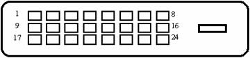
DVI-D 24 PIN CONNECTOR
Pin No. |
Signal Name |
Description |
|
|
|
1 |
RX2- |
TMDS negative differential input, channel 2 |
|
|
|
2 |
RX2+ |
TMDS positive differential input, channel 2 |
|
|
|
3 |
GND |
Logic Ground |
|
|
|
4 |
Reserved 4 |
Reserved. No connection |
|
|
|
5 |
Reserved 5 |
Reserved. No connection |
|
|
|
6 |
DDC-CLK |
DDC2B Clock |
7 |
DDC-DAT |
DDC2B Data |
|
|
|
8 |
Reserved 8 |
Reserved. No connection |
9 |
RX1- |
TMDS negative differential input, channel 1 |
10 |
RX1+ |
TMDS positive differential input, channel 1 |
11 |
GND |
Logic Ground |
12 |
Reserved 12 |
Reserved. No connection |
13 |
Reserved 13 |
Reserved. No connection |
|
|
|
14 |
VCCX |
Power |
|
|
|
15 |
GND |
Logic Ground |
|
|
|
16 |
SENS |
SENSE Pin, Pull High |
|
|
|
17 |
RX0- |
TMDS negative differential input, channel 0 |
|
|
|
18 |
RX0+ |
TMDS positive differential input, channel 0 |
|
|
|
19 |
GND |
Logic Ground |
|
|
|
20 |
Reserved 20 |
Reserved. No connection |
|
|
|
21 |
Reserved 21 |
Reserved. No connection |
|
|
|
22 |
GND |
Logic Ground |
|
|
|
23 |
RXC+ |
TMDS positive differential input, reference clock |
|
|
|
24 |
RXC- |
TMDS negative differential input, reference clock |
|
|
|
|
|
- 10 – |
ViewSonic Corporation
3.Front Panel Function Controls And Indicators
- 11 –
ViewSonic Corporation

Do the following to adjust the display setting: 1. To display the Main Menu, press button [1].
NOTE: All OSD menus and adjustment screens disappear automatically after about 15 seconds. This is adjustable through the OSD timeout setting in the setup menu.
2.To select a control to adjust, press or ▼ to ▲ scroll up or down in the Main Menu.
3.After the desired control is selected, press button [2]. A control screen like the one shown below appears.
The command line at the bottom of the control screen tells what to do next from this screen. You can toggle between control screens, adjust the selected option, or exit the screen.
4.To adjust the setting, press the up ▼ or ▲ down T buttons.
5.To save the adjustments and exit the menu, press button [1] twice.
The following tips may help you optimize your display:
•Adjust the computer's graphics card so that it outputs a 1280 x 1024 @ 60Hz video signal to the LCD display. (Look for instructions on “changing the refresh rate” in the graphics card's user guide.)
•If necessary, make small adjustments using H. POSITION and V. POSITION until the screen image is completely visible. (The black border around the edge of the screen should barely touch the illuminated “active area” of the LCD display.)
- 12 –
ViewSonic Corporation

Main Menu Controls
Adjust the menu items shown below by using the up  and down
  buttons.
Control |
Explanation |
Auto Image Adjust sizes and centers the screen image automatically.
Contrast adjusts the difference between the image background (black level) and the foreground (white level).
Brightness adjusts background black level of the screen image.
Input Select allows the user to toggle between an analog and a digital signal.
Audio Adjust
Volume increases the volume, decreases the volume, and mutes the audio. Mute temporarily silences audio output.
Color Adjust provides several color adjustment modes, including preset color temperatures and a User Color mode which allows independent adjustment of red (R), green (G), and blue (B). The factory setting for this product is 6500K (6500 Kelvin).
9300K-Adds blue to the screen image for cooler white (used in most office settings with fluorescent lighting).
6500K-Adds red to the screen image for warmer white and richer red. 5400K-Adds green to the screen image for a darker color. 5000K-Adds blue and green to the screen image for a darker color. User Color Individual adjustments for red (R), green (G), and blue (B).
1.To select color (R, G or B) press button [2].
2.To adjust selected color, press ▼ and ▲.
Important: If you select RECALL from the Main Menu when the product is set to a Preset Timing Mode, colors return to the 6500K factory preset.
- 13 –
ViewSonic Corporation
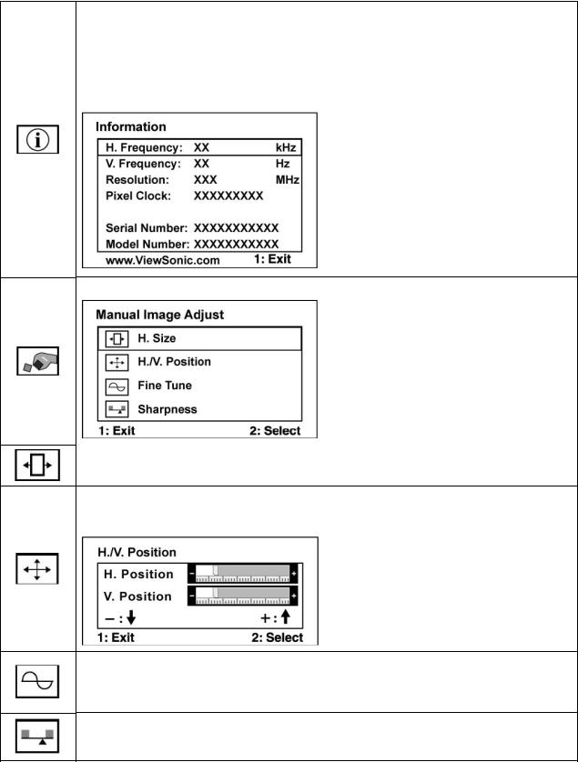
Information displays the timing mode (video signal input) coming from the graphics card in the computer, the LCD model number, the serial number, and
the ViewSonic® website URL. See your graphics card’s user guide for instructions on changing the resolution and refresh rate (vertical frequency). NOTE: VESA 1280 x 1024 @ 60Hz (recommended) means that the resolution is 1280 x 1024 and the refresh rate is 60 Hertz.
Manual Image Adjust Sub-menu
H. Size (Horizontal Size) adjusts the width of the screen image.
H./V. Position (Horizontal/Vertical Position) moves the screen image left or right and up or down.
Fine Tune sharpens the focus by aligning text and/or graphics with pixel boundaries.
NOTE: Try Auto Image Adjust first.
Sharpness adjusts the clarity and focus of the screen image.
- 14 –
ViewSonic Corporation
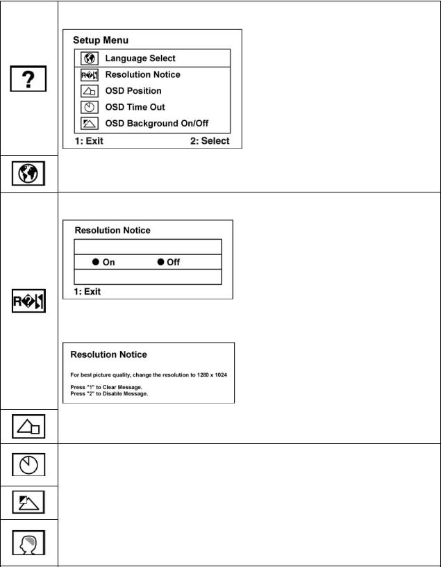
Setup Menu displays the menu shown below:
Language Select allows the user to choose the language used in the menus and control screens.
Resolution Notice allows the user to enable or disable this notice.
If you enable the Resolution Notice shown above and your computer is set at a resolution other than 1280 x 1024, the following screen appears.
OSD Position allows the user to move the OSD menus and control screens.
OSD Timeout sets the length of time the OSD screen is displayed. For example, with a “30 second” setting, if a control is not pushed within 30 seconds, the display screen disappears.
OSD Background allows the user to turn the OSD background On or Off.
Memory Recall returns the adjustments back to factory settings if the display is operating in a factory Preset Timing Mode listed in the Specifications of this manual.
- 15 –
ViewSonic Corporation

SHORT CUTS FUNCTION FROM THE BUTTONS
[1] |
Main Menu |
|
|
|
|
[2] |
Auto Image Adjust |
|
|
|
|
[▼] or [▲] |
To immediately activate Contrast menu. It should be |
|
change to Brightness OSD by push button [2] |
||
|
||
|
|
|
[▼] + [▲] |
Recall Contrast or Brightness while in the Contrast or |
|
Brightness adjustment, or recall both of Contrast and |
||
|
Brightness when the OSD is not open. |
|
|
|
|
[1] + [2] |
Toggle 720x400 and 640x400 mode when input 720x400 |
|
or 640x400 mode |
||
|
||
|
|
|
[1] + [▼] + [▲] |
White Balance (Not shown on user’s guide) |
|
|
|
|
|
• Power Lock: Press and hold “[2], & ▼” for 10 seconds. |
|
|
If the power button is pressed the message Power |
|
[1] + [▼] |
Button Locked will display for 5 seconds. With or without |
|
this setting, after a power failure, your LCD display’s |
||
|
power will automatically turn ON when power is restored. |
|
|
• Power Unlock: Press and hold “[2], & ▼” again for 10 |
|
|
seconds. |
|
|
|
|
|
• OSD Lock: Press and hold "[1], & (▲)" for 10 seconds. |
|
[1] + [▲] |
If any buttons are pressed the message OSD Locked will |
|
display for 5 seconds. |
||
|
• OSD Unlock: Press and hold “[1], & ▲” again for 10 |
|
|
seconds. |
|
|
|
|
[; ] |
Volume mute on/off |
|
|
|
Remark : All the short cuts function are only available while OSD off
- 16 –
ViewSonic Corporation

4.Circuit Description
4.1LCD MONITOR DESCRIPTION
The LCD MONITOR will contain a Main Board, an Power Board, Key Board which house the flat panel control logic, brightness control logic and DDC.
The Power Board will provide AC to DC Inverter voltage to drive the backlight of panel and the Main Board chips each voltage.
Monitor Block Diagram
CCFL Drive. |
Flat Panel and |
|
CCFL backlight |
|
|
|
|
|
|
|
|
|
|
RS232 Connector |
Power Board |
|
|
Main Board |
|
|
|||
|
|
|
|
For white balance |
||||
(Include: adapter, inverter) |
|
|
|
|
|
|
|
|
|
|
|
|
|
|
|
adjustment in factory |
|
|
|
|
|
|
|
|
|
|
|
|
|
|
|
|
|
|
mode |
|
|
|
|
|
|
|
|
|
|
|
|
|
|
|
|
|
|
|
|
|
|
|
|
|
|
Video signal, DDC |
|
|
Key Board |
|
|
|
|
||
|
|
|
|
|
|
|||
AC-IN |
|
|
|
|
|
|
|
|
|
|
|
|
|
|
|
||
|
|
|
|
HOST Computer |
|
|
||
100V-240V |
|
|
|
|
|
|
|
|
- 17 –
ViewSonic Corporation
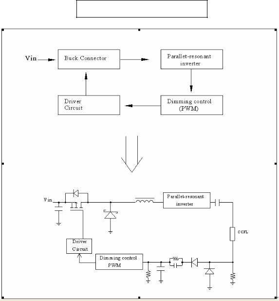
4.2POWER BLOCK FUNCTION DESCRIPTION
Inverter Block Function
- 18 –
ViewSonic Corporation
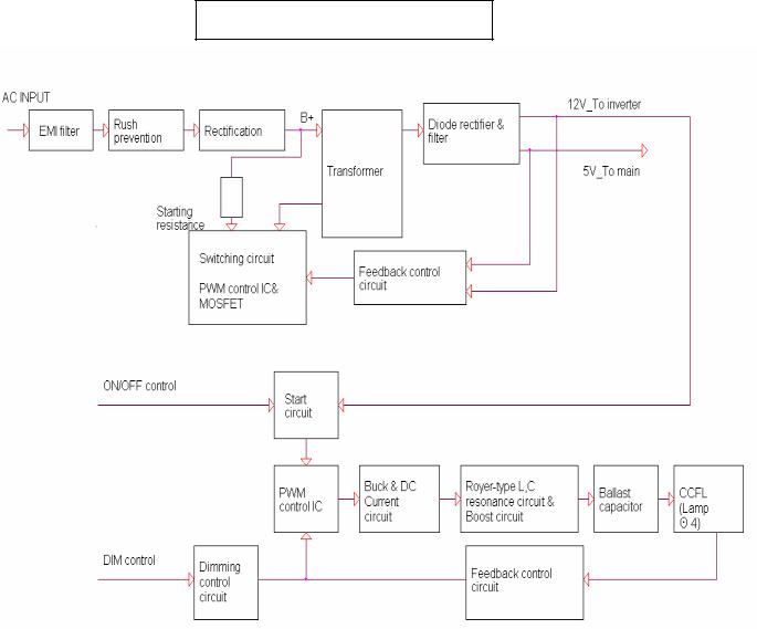
Power Block Function
- 19 –
ViewSonic Corporation
4.4 INTRODUCTION OF IC
RTD2523B-LF(U401): integrate ADC, OSD, TMPS, RSDS TX, LVDS TX, convert analog RGB into digital and room and shrink scaling output to LCD panel.
PIN Function:
Pin |
Symbol |
Description |
127 |
XO |
Crystal OSC output |
128 |
XI |
Reference clock input from external crystal or from |
|
|
single-ended CMOS/TTL OSC 3.3V tolerance |
50 |
DDCSCL1 ADC |
Open drain Internal 75K pull high |
51 |
DDCSDA1 ADC |
Open drain Internal 75K pull high |
121 |
DDCSCL2 DVI |
Open drain Internal 75K pull high |
120 |
DDCSDA2 DVI |
Open drain Internal 75K pull high |
123 |
RESET_OUT |
Reset out Open drain( internal 75KOhm high) |
110/48 |
COUT |
Crystal out |
124 |
33VRST_REF |
Reference 3.3V for Reset Out |
109 |
33VPNLOUT |
Panel on/off switch out Max current driving 1A |
58 |
BJT_B |
Embedded regulator P type BJT control pin out |
5 |
TMDS_TST |
TMDS_TEST Pin; |
|
|
Power-on-latch for host interface type. |
7/13 |
TMDS_VDD |
TMDS power 3.3V |
6 |
REXT |
Impedance Match Reference. |
49/112 |
PWM2 |
|
4/48/111 |
PWM1 |
|
3/5/122 |
PWM0 |
|
4 |
BYPASS |
For External Bypass Capacitor |
125 |
DPLL_VDD |
Power for digital PLL 3.3V |
2 |
APLL_VDD |
Power for multi-phase PLL 3.3V |
3 |
PLL_TEST1 |
Test Pin 1;Power-on-latch for MCU crystal location |
4 |
PLL_TEST2 |
Test Pin 2;Power-on-latch for crystal in frequency |
56/118 |
SCSB |
Serial control I/F chip select Open drain |
57/119 |
SCLK |
Serial control I/F clock Open drain |
59/83/108 |
Pad 3.3V Power |
PVCC |
47/116 |
Digital 1.8V Power |
VCCK |
21/38 |
ADC_VDD |
ADC Power 1.8V |
40 |
VCLK |
Video8 Clock |
19 |
AVSO |
ADC vertical sync input |
|
|
5V tolerance |
|
|
Power from PIN 13 |
20 |
AHSO |
ADC horizontal sync input |
|
|
Adjustable Schmidt trigger 5V tolerance |
|
|
Power from PIN 13 |
AIC1084-33PM (U701): DC power convert, used to 5v convert 3.3v.
- 20 –
ViewSonic Corporation
MTV512GMV64 (U402): The MTV512M micro-controller is an 8051 CPU core embedded device especially tailored for flat panel display applications. It includes an 8051 CPU core, 768-byte SRAM, 4 channels of 6-bit ADC, 3 external counters/timers, 6 channels of PWM DAC, VESA DDC interface, and a 64K-byte internal program Flash-ROM memory.
Circuit Diagram
- 21 –
ViewSonic Corporation

PIN Function
Name |
Pin No. |
DESCRIPTION |
||
PLCC |
QFP |
|||
|
|
|||
NC |
1 |
39 |
No connection |
|
DA0/P5.0 |
2 |
40 |
PWM DAC output/General purpose I/O (open drain) |
|
DA1/P5.1 |
3 |
41 |
PWM DAC output/General purpose I/O (open drain) |
|
DA2/P5.2 |
4 |
42 |
PWM DAC output/General purpose I/O (open drain) |
|
DA3/P5.3 |
5 |
43 |
PWM DAC output/General purpose I/O (open drain) |
|
DA4/P5.4 |
6 |
44 |
PWM DAC output/General purpose I/O (open drain) |
|
DA5/P5.5 |
7 |
1 |
PWM DAC output/General purpose I/O (open drain) |
|
P5.6/HSCL2 |
8 |
2 |
General purpose I/O/Slave llC1 SCL2 open drain |
|
P5.7/HSDA2 |
9 |
3 |
General purpose Output/Slave llC1 SCL2 open drain |
|
RST |
10 |
4 |
High Active RESET |
|
HSCL1/P3.0/RXD |
11 |
5 |
Slave IIC clock/General purpose I/O/Rxd (open drain) |
|
HSDA1/P3.1/RXD |
13 |
7 |
Slave IIC clock/General purpose I/O/Txd (open drain) |
|
P3.2/INT0 |
14 |
8 |
General purpose I/O/External interrupt 0(Standard 8051) |
|
|
|
|
- 22 – |
|
ViewSonic Corporation

P3.3/INT1 |
15 |
9 |
General purpose I/O/External interrupt 1(Standard 8051) |
P3.4/T0 |
16 |
10 |
General purpose I/O/T0 Ext. Counter/Timer 0(Standard8051) |
P3.5/T1 |
17 |
11 |
General purpose I/O/T1 Ext. Counter/Timer 1(Standard8051) |
P7.6/CLKO2 |
18 |
12 |
General purpose I/O/Clock out 2 (CMOS) |
P7.7 |
19 |
13 |
General purpose I/O (CMOS) |
X2 |
20 |
14 |
Crystal Out |
X1 |
21 |
15 |
Crystal In |
VSS |
22 |
16 |
Ground |
P6.0/AD0 |
24 |
18 |
General purpose I/O(COMS)/6-bit ADC channel 0 input |
P6.1/AD1 |
25 |
19 |
General purpose I/O(COMS)/6-bit ADC channel 1 input |
P6.2/AD2 |
26 |
20 |
General purpose I/O(COMS)/6-bit ADC channel 2 input |
P6.3/AD3 |
27 |
21 |
General purpose I/O(COMS)/6-bit ADC channel 3 input |
P6.4 |
28 |
22 |
General purpose I/O(COMS) |
P6.5 |
29 |
23 |
General purpose I/O(COMS) |
P6.6/CLKO1 |
30 |
24 |
General purpose I/OCLKO1(COMS) |
P6.7 |
31 |
25 |
General purpose I/O(COMS) |
VSYNC |
32 |
26 |
VSYNC input |
P1.7 |
36 |
30 |
General purpose I/O(Standard 8051/CMOS) |
P1.6 |
37 |
31 |
General purpose I/O(Standard 8051/CMOS) |
P1.5 |
38 |
32 |
General purpose I/O(Standard 8051/CMOS) |
P1.4 |
39 |
33 |
General purpose I/O(Standard 8051/CMOS) |
P1.3 |
40 |
34 |
General purpose I/O(Standard 8051/CMOS) |
P1.2 |
41 |
35 |
General purpose I/O(Standard 8051/CMOS) |
P1.1 |
42 |
36 |
General purpose I/O(Standard 8051/CMOS) |
P1.0/ET2 |
43 |
37 |
General purpose I/O/External Counter/Timer2(Standard |
|
8051/CMOS) |
||
|
|
|
|
VCC |
44 |
38 |
3.3V power |
TDA7496L (U201): The UTC TDA7496L is a stereo 2W+2W class AB power amplifier, specially designed for high quality sound, TV and Monitor applications. Features of the UTC TDA7496L include linear volume control, Stand-by and mute functions.
Pin Function
- 23 –
ViewSonic Corporation

Circuit Diagram
LD7552BS (IC901): PWM control, high-voltage startup current. The circuit unit has functions such as over-current protection, over-voltage protection, output short-circuit protection and etc. The function of each pin and the inside circuit diagram are as follows:
Pin |
Name |
Function |
|
1 |
GND |
Ground |
|
|
|
Voltage feedback pin (same as the COMP pin in UC384X), By |
|
2 |
COMP |
connecting a photo-coupler to close the control loop and achieve the |
|
|
|
regulation |
|
3 |
VCC |
Supply voltage pin |
|
|
|
|
|
4 |
RT |
This pin is to program the switching frequency. By connecting a resistor |
|
to ground to set the switching frequency. |
|||
|
|
||
6 |
NC |
Unconnected pin |
|
7 |
VCC |
Supply voltage pin |
|
8 |
OUT |
Gate drive output to drive the external MOSFET |
- 24 –
ViewSonic Corporation

FAN7547A(IC201): The FAN7547A provides all control functions for a current fed push-pull self oscillation type converter, and also contains voltage. Typical operating frequency range is between 30kHz depending on the CCFL(Cold Cathode Fluorescent Lamp) and the transformer’s characteristics:
NO. |
Name |
Function Description |
|
NO. |
Name |
Function Description |
|
|
|
|
|
|
|
1 |
GNDT |
Ground |
|
8 |
FB |
Feedback Input |
|
|
|
|
|
|
|
2 |
Vds |
Dimming Voltage Input |
|
9 |
COMP |
Error Amplifier Output |
|
|
|
|
|
|
|
3 |
Vref |
Reference Voltage |
|
10 |
S/S |
Soft Start |
|
|
|
|
|
|
|
4 |
Vms |
Dimming Mode Selection |
|
11 |
OSC |
Main Ct |
|
|
|
|
|
|
|
5 |
Rct |
Burst Dimming Frequency |
|
12 |
Vcc |
Supply Voltage |
Set |
|
|||||
|
|
|
|
|
|
|
6 |
OLP |
Open Lamp Protection |
|
13 |
Vcc1 |
Output Drive Source Voltage |
|
|
|
|
|
|
|
7 |
SDP |
Shutdown Protection |
|
14 |
OUT |
Output Drive |
|
|
|
|
|
|
|
ViewSonic Corporation |
- 25 – |
|
|
|||
|
|
|
|
|||

- 26 –
ViewSonic Corporation
5. Adjust Procedure
5.1ADJUSTMENT CONDITIONS AND PRECAUTIONS
1.Approximately 30 minutes should be allowed for warm up before proceeding.
2.Adjustments should be undertaken only on those necessary elements since most of them have been carefully preset at the factory.
3.ESD protection is needed before adjustment.
5.2MAIN ADJUSTMENTS
NO. |
FUNCTIONS |
DESIGNATION |
1. |
White Balance |
Function Key |
2. |
Geometry |
Function Key |
5.3ALIGNMENT PROCEDURES
Approximately 30 minutes should be allowed for warm up before proceeding White-Balance adjustment.
1.Adjust of White Balance
1.)How to do the Chroma-7120 MEM .Channel setting
A Reference to Chroma 7120 user guide
B Use “ SC” key and “ NEXT” key to modify xyY value and use “ID” key to modify the TEXT description Following is the procedure to do white-balance adjust
2.)Setting the color temp. You want
A MEM.CHANNEL9 ( 9300 color):
9300 color temp. parameter is Wx = 0.283 ±0.02;Wy = 0.298 ±0.02;
Y > 190 cd/m2 , B MEM.CHANNEL10 ( 6500 color):
6500 color temp. parameter is Wx = 0.313±0.02;Wy = 0.329 ±0.02;
Y > 260 cd/m2, C MEM.CHANNEL 11 ( 5400 color):
5400 color temp. parameter is Wx = 0.335±0.02;Wy = 0.350 ±0.02;
Y > 210 cd/m2, D MEM.CHANNEL 12 ( 5000 color):
5000 color temp. parameter is Wx = 0.346±0.02;Wy = 0.359 ±0.02;
Y > 210 cd/m2 E MEM.CHANNEL13 ( SRGB color):
SRGB color temp. parameter is Wx = 0.313±0.02;Wy = 0.329 ±0.02; Y > 220 cd/m2,
- 27 –
ViewSonic Corporation
3.)Into factory mode of VA712b-2
A First Power off, then press Switch 2 button along with press Power button will activate
the factory mode, then MCU will do AUTO LEVEL automatically. Meanwhile press MENU the OSD screen will located at LEFT TOP OF PANEL.
4.)Bias adjustment :
Set the Contrast to 70
to 70
Adjust the Brightness  to 100.
5.)Gain adjustment :
Move cursor to “-F-” and press MENU key
A Adjust 9300 color-temperature
(1) Switch the Chroma-7120 to RGB-Mode (with press “MODE” button )
(2) Switch the MEM. channel to Channel 9 ( with up or down arrow on Chroma 7120 )
(3) The LCD-indicator on Chroma 7120 will show x = 0.283 ±0.02, y =0.298 ±0.02,
Y > 250 cd/m2
(4) Adjust the RED of color1 on factory window until chroma 7120 indicator reached the value R=100
(5) Adjust the GREEN of color1 on factory window until Chroma 7120 indicator reached the value G=100
(6) Adjust the BLUE of color1 on factory window until Chroma 7120 indicator reached the value B=100
(7) Repeat above procedure ( item 4,5,6) until Chroma 7120 RGB value meet the tolerance =100±5
B Adjust 6500 color-temperature
(1) Switch the chroma-7120 to RGB-Mode (with press “MODE” button )
(2) Switch the MEM .channel to Channel 10( with up or down arrow on Chroma 7120 )
(3) The LCD-indicator on Chroma 7120 will show x = 0.313 ±0.02, y = 0.329 ±0.02,
Y>260 cd/m2
(4) Adjust the RED of color3 on factory window until Chroma 7120 indicator reached the value R=100
(5) Adjust the GREEN of color3 on factory window until Chroma 7120 indicator reached
the value G=100
(6) Adjust the BLUE of color3 on factory window until Chroma 7120 indicator reached
the value B=100
(7) Repeat above procedure ( item 4,5,6) until Chroma 7120 RGB value meet the tolerance =100±5
- 28 –
ViewSonic Corporation
 Loading...