


Toshiba RAS-18SKV-E2, RAS-22SKV-E, RAS-18SKV-E, RAS-22SAV-E, RAS-22SAV-E2 Installation Manual
...INSTALLATION MANUAL
AIR CONDITIONER (SPLIT TYPE)
Indoor unit  RAS-18, 22SKV(R) Series
Outdoor unit
RAS-18, 22SAV Series
ENGLISH
ESPAÑOL
FRANÇAIS
ITALIANO
DEUTSCH
PORTUGUÊS
POLSKI
ÿESKY
PУCСКИЙ
HRVATSKI
MAGYAR
TÜRKÇE
NEDERLANDS
ΕΛΛΗΝΙΚΑ
SVENSKA
SUOMI
NORSK
DANSK
ROMÂNĄ
БЪЛГАРСКИ
EESTI
LATVISKI
SLOVENÿINA
SLOVENŠÿINA
065 0 -CoverF- .indd |
3/6/08 5:0 :34 PM |

EN CONTENTS |
|
PRECAUTIONS FOR SAFETY.................................................... |
|
INSTALLATION DIAGRAM OF INDOOR AND |
|
OUTDOOR UNITS ....................................................................... |
3 |
Optional Installation Parts ....................................................... |
3 |
INDOOR UNIT.............................................................................. |
4 |
Installation Place ..................................................................... |
4 |
Cutting a Hole and Mounting Installation Plate ....................... |
4 |
Wiring Connection................................................................... |
5 |
Piping and Drain Hose Installation .......................................... |
5 |
Indoor Unit Fixing .................................................................... |
6 |
Drainage.................................................................................. |
6 |
OUTDOOR UNIT.......................................................................... |
6 |
Installation Place ..................................................................... |
6 |
Precautions about Installation in Regions with Snowfall and |
|
Cold Temperatures .................................................................. |
6 |
Refrigerant Piping Connection ................................................ |
7 |
Evacuating .............................................................................. |
7 |
Wiring Connection................................................................... |
7 |
Electrical Work ........................................................................ |
7 |
OTHERS....................................................................................... |
8 |
Gas Leak Test ......................................................................... |
8 |
Setting of Remote Control Selector Switch ............................. |
8 |
Remote Control A-B Selection................................................. |
8 |
Test Operation ........................................................................ |
8 |
Auto Restart Setting ............................................................... |
8 |
ES CONTENIDOS |
|
PRECAUCIONES SOBRE SEGURIDAD .................................... |
|
DIAGRAMA DE INSTALACIÓN DE LA UNIDAD INTERIOR Y |
|
EXTERIOR ................................................................................... |
3 |
Piezas de Instalación Opcional .............................................. |
3 |
UNIDAD INTERIOR ..................................................................... |
4 |
Lugar de Instalación................................................................ |
4 |
Corte de un Orifi cio y Montaje de la Placa de Instalación ...... |
4 |
Conexión de Cables................................................................ |
5 |
Instalación la Tubería y el Tubo de Desagüe ......................... |
5 |
Instalación de la Unidad Interior.............................................. |
6 |
Drenaje ................................................................................... |
6 |
UNIDAD EXTERIOR .................................................................... |
6 |
Lugar de Instalación................................................................ |
6 |
Precauciones sobre Instalación en Regiones con Nieve y |
|
Temperaturas Frías ................................................................. |
6 |
Conexión de la Tubería Refrigerante ...................................... |
7 |
Evacuación ............................................................................. |
7 |
Conexión de Cables................................................................ |
7 |
Trabajo Eléctrico ..................................................................... |
7 |
OTROS......................................................................................... |
8 |
Comprobación de Fugas......................................................... |
8 |
Confi guración del interruptor de selección del mando a distancia .. |
8 |
Mando a distancia A-B Selección............................................ |
8 |
Prueba de Operación ............................................................. |
8 |
Ajuste de Reinicio Automático ................................................ |
8 |
FR SOMMAIRE |
|
MESURES DE SÉCURITÉ........................................................... |
|
PLAN D’INSTALLATION DES UNITÉS INTÉRIEURE ET |
|
EXTÉRIEURE............................................................................... |
3 |
Pièces d’Installation en Option ............................................... |
3 |
UNITÉ INTÉRIEURE.................................................................... |
4 |
Endroit d’Installation................................................................ |
4 |
Ouverture du Trou et Montage de la Plaque d’Installation ..... |
4 |
Connexion des Câbles ............................................................ |
5 |
Installation de la Conduite et du Tuyau de Purge ................... |
5 |
Installation de l’Unité Intérieure............................................... |
6 |
Drainage ................................................................................. |
6 |
UNITÉ EXTÉRIEURE................................................................... |
6 |
Endroit d’Installation................................................................ |
6 |
Précautions à prendre pour l’installation dans les régions |
|
sujettes aux chutes de neige et aux températures froides...... |
6 |
Connexion du Tuyau Réfrigérant............................................. |
7 |
Evacuation .............................................................................. |
7 |
Connexion des Câbles ............................................................ |
7 |
Travaux Electriques ................................................................ |
7 |
AUTRES....................................................................................... |
8 |
Test de Fuite Gaz .................................................................... |
8 |
Réglage du sélecteur de télécommande................................. |
8 |
Sélection de télécommande A-B ............................................. |
8 |
Opération du Test ................................................................... |
8 |
Réglage de la Remise en Marche Automatique ..................... |
8 |
IT INDICE |
|
PRECAUZIONI PER LA SICUREZZA ......................................... |
|
SCHEMA DI INSTALLAZIONE DELL’ UNITÀ INTERNA |
|
E DELL’ UNITÀ ESTERNA.......................................................... |
3 |
Componenti di Installazione Opzionali ................................... |
3 |
UNITÀ INTERNA ......................................................................... |
4 |
Luogo per l’Installazione.......................................................... |
4 |
Apertura di un Foro e Installazione della Lastra di Installazione... |
4 |
Collegamento dei Cavi ............................................................ |
5 |
Installazione dei Tubi e del Tubo di Scarico ............................ |
5 |
Installazione dell’Unità Interna ................................................ |
6 |
Scarico .................................................................................... |
6 |
UNITÀ ESTERNA ........................................................................ |
6 |
Luogo per l’Installazione.......................................................... |
6 |
Precauzioni sull’installazione nelle regioni |
|
soggette a nevicate e basse temperature ............................... |
6 |
Collegamento dei Tubi del Refrigerante.................................. |
7 |
Evacuazione ........................................................................... |
7 |
Collegamento dei Cavi ............................................................ |
7 |
Lavori Elettrici.......................................................................... |
7 |
ALTRI ........................................................................................... |
8 |
Test per Perdite di Gas............................................................ |
8 |
Impostazione del selettore del telecomando........................... |
8 |
Selezione A-B del telecomando .............................................. |
8 |
Funzionamento di Prova ......................................................... |
8 |
Impostazione per la Rimessa in Funzione Automatica ........... |
8 |
DE INHALT |
|
SICHERHEITSVORKEHRUNGEN .............................................. |
|
EINBAUZEICHNUNGEN FÜR INNENUND |
|
AUSSENGERÄT.......................................................................... |
3 |
Zusätzlich erhältliche Installationsteile ................................... |
3 |
INNENGERÄT.............................................................................. |
4 |
Aufstellungsort......................................................................... |
4 |
Mauerdurchbruch und Befestigung der Montageplatte .......... |
4 |
Kabelanschlüsse ..................................................................... |
5 |
Installation von Leitungen und Kondensatschlauch ................ |
5 |
Einbau des Innengeräts .......................................................... |
6 |
Entwässerung ......................................................................... |
6 |
AUSSENGERÄT.......................................................................... |
6 |
Aufstellungsort......................................................................... |
6 |
Vorsichtsmaßnahmen beim Einbau in Regionen |
|
mit Schneefall und kalten Temperaturen ................................. |
6 |
Anschluß der Kühlmittelleitungen............................................ |
7 |
Entleeren ................................................................................ |
7 |
Kabelanschlüsse ..................................................................... |
7 |
Elektrische Anschlüsse ........................................................... |
7 |
SONSTIGES................................................................................. |
8 |
Überprüfung auf Gas-Undichtigkeit......................................... |
8 |
Einstellen des Fernbedienungs-Wahlschalters ....................... |
8 |
Fernbedienung A-B Wahl ........................................................ |
8 |
Probelauf................................................................................. |
8 |
Automatische Wiedereinschaltung.......................................... |
8 |
PT ÍNDICE |
|
PRECAUÇÕES RELATIVAS A SEGURANÇA............................ |
|
ESQUEMA DE INSTALAÇÃO DAS UNIDADES INTERIOR |
|
E EXTERIOR................................................................................ |
3 |
Peças de Instalação Opcionais............................................... |
3 |
UNIDADE INTERIOR................................................................... |
4 |
Local de Instalação ................................................................. |
4 |
Cortar um Orifício e Montar a Placa de Instalação ................. |
4 |
Ligações Eléctricas ................................................................. |
5 |
Instalação da Tubagem e do Tubo Flexível de Dreno............. |
5 |
Colocação da Unidade Interior................................................ |
6 |
Drenagem................................................................................ |
6 |
UNIDADE EXTERIOR.................................................................. |
6 |
Local de Instalação ................................................................. |
6 |
Precauções na instalação em regiões com queda de neve e |
|
temperaturas negativas........................................................... |
6 |
Ligação das Condutas de Refrigeração.................................. |
7 |
Purga de Ar ............................................................................. |
7 |
Ligações Eléctricas ................................................................. |
7 |
Trabalhos de Electricidade...................................................... |
7 |
OUTROS ...................................................................................... |
8 |
Teste de Fugas de Gás ........................................................... |
8 |
Defi nição do interruptor do telecomando ................................ |
8 |
Selecção A-B do telecomando ................................................ |
8 |
Execução do Teste .................................................................. |
8 |
Defi nindo de Reiniciação Automática...................................... |
8 |
PL SPIS TREŊCI |
|
ZASADY BEZPIECZEķSTWA..................................................... |
|
SCHEMAT INSTALACYJNY URZĆDZENIA WEWNĔTRZNEGO |
|
I ZEWNĔTRZNEGO..................................................................... |
3 |
Dodatkowe Czĕŋci Instalacyjne............................................... |
3 |
URZĆDZENIE WEWNĔTRZNE ................................................... |
4 |
Miejsce Instalacji ..................................................................... |
4 |
Wycinanie Otworu oraz Montaŧ Pãyty Instalacyjnej................. |
4 |
Podãćczenie Okablowania....................................................... |
5 |
Montaŧ Instalacji Rurowej i Wĕŧa do Odprowadzania Cieczy .. |
5 |
Mocowanie Urzćdzenia Wewnĕtrznego .................................. |
6 |
Odprowadzanie Cieczy ........................................................... |
6 |
URZĆDZENIE ZEWNĔTRZNE .................................................... |
6 |
Miejsce Instalacji ..................................................................... |
6 |
Zalecenia dotyczćce instalacji urzćdzenia w rejonach z |
|
wystĕpowaniem obfi tych opadów ŋniegu i niskich temperatur .......... |
6 |
âćczenie Instalacji Rurowej Czynnika Chãodniczego .............. |
7 |
Usuwanie Powietrza................................................................ |
7 |
Podãćczenie Okablowania....................................................... |
7 |
Prace Elektryczne ................................................................... |
7 |
INNE............................................................................................. |
8 |
Próba Gazoszczelnoŋci........................................................... |
8 |
Ustawianie przeãćcznika wyboru pilota.................................... |
8 |
Ustawienia przeãćcznika A-B wyboru pilota............................. |
8 |
Próba Dziaãania....................................................................... |
8 |
Wãćczanie Funkcji Automatycznego Wznawiania Pracy (Auto Restart) .. |
8 |
CZ OBSAH |
|
BEZPEÿNOSTNÍ OPATňENÍ ...................................................... |
|
SCHÉMA INSTALACE VNITňNÍ A VENKOVNÍ JEDNOTKY...... |
3 |
Volitelné Doplļky pro Instalaci ................................................ |
3 |
VNITňNÍ JEDNOTKA .................................................................. |
4 |
Místo Instalace ........................................................................ |
4 |
Vyvrtání Otvoru a Montáž InstalaĀní Desky ............................ |
4 |
Zapojení VodiĀś....................................................................... |
5 |
Montáž Trubek a Vypouštėcí Hadice....................................... |
5 |
Montáž Vnitʼnní Jednotky.......................................................... |
6 |
Odvod Vody............................................................................. |
6 |
VENKOVNÍ JEDNOTKA.............................................................. |
6 |
Místo Instalace ........................................................................ |
6 |
Pokyny pro instalaci v oblastech, kde padá sníh a |
|
jsou nízké teploty..................................................................... |
6 |
Spojování Chladivového Potrubí............................................. |
7 |
VyĀerpávání Vzduchu.............................................................. |
7 |
Zapojení VodiĀś....................................................................... |
7 |
Elektrické Práce ...................................................................... |
7 |
OSTATNİ...................................................................................... |
8 |
Zkouška Úniku Plynu............................................................... |
8 |
Nastavení pʼnepínaĀe dálkového ovládání ............................... |
8 |
Volba A-B na dálkovém ovládání............................................. |
8 |
Zkušební Provoz ..................................................................... |
8 |
Nastavení Automatického Znovuspuštėní............................... |
8 |
RU СОДЕРЖАНИЕ |
|
MEPЫ БEЗOПACHOCTИ ........................................................... |
|
СХЕМА УСТАНОВКИ ВНУТРЕННЕГО И НАРУЖНОГО |
|
БЛОКОВ...................................................................................... |
3 |
Oпционaльныe Уcтaновочныe Чacти ................................... |
3 |
BHУTPEHHИЙ БЛOК................................................................. |
4 |
Mecто Уcтaновки ................................................................... |
4 |
Пpоpeзaниe Отвepcтия и Монтaж Уcтaновочной Плacтины.. |
4 |
Элeктpичecкиe Cоeдинeния ................................................ |
5 |
Уcтaновкa Tpyбопpоводов и Дpeнaжной Tpyбки ................ |
5 |
Уcтaновкa Bнyтpeннeго Блокa............................................. |
6 |
Дpeнaж ................................................................................... |
6 |
HAPУЖHЫЙ БЛOК.................................................................... |
6 |
Mecто Уcтaновки ................................................................... |
6 |
Меры безопасности при установке в регионах, в которых |
|
возможно выпадение снега и низкие температуры ............... |
6 |
Подcоeдинeниe Tpyбопpоводa для Xлaдaгeнтa ................. |
7 |
Удaлeниe Воздyxa................................................................. |
7 |
Элeктpичecкиe Cоeдинeния ................................................ |
7 |
Элeктpомонтaжныe Рaботы................................................. |
7 |
ДPУГИE ....................................................................................... |
8 |
Пpовepкa Отcyтcтвия Утeчки Гaзa...................................... |
8 |
Уcтaновкa положeния пepeключaтeля диcтaнционного yпpaвлeния.. |
8 |
Выбор А-В на пульте ДУ ....................................................... |
8 |
Пpобнaя Экcплyaтaция......................................................... |
8 |
Уcтaновкa Aвтомaтичecкого Повтоpного Пycкa................. |
8 |
CR SADRŽAJ |
|
MJERE SIGURNOSTI.................................................................. |
|
SHEMA UGRADNJE UNUTARNJIH I VANJSKIH JEDINICA..... |
3 |
Dodatni Dijelovi za Ugradnju Prema Izboru ........................... |
3 |
UNUTARNJA JEDINICA.............................................................. |
4 |
Mjesto Ugradnje ...................................................................... |
4 |
Izrezivanje Rupe i Postavljanje PloĀe za Ugradnju................. |
4 |
ŽiĀana Veza............................................................................. |
5 |
Ugradnja Cijevi i Crijeva za Pražnjenje ................................... |
5 |
UĀvršþivanje Unutarnje Jedinice ............................................. |
6 |
Ispust....................................................................................... |
6 |
VANJSKA JEDINICA................................................................... |
6 |
Mjesto Ugradnje ...................................................................... |
6 |
Mjere opreza za montažu u podruĀjima s jakim snijegom i |
|
niskim temperaturama............................................................. |
6 |
Sklop Cijevi Rashladnog Sredstva .......................................... |
7 |
Pražnjenje ............................................................................... |
7 |
ŽiĀana Veza............................................................................. |
7 |
ElektriĀni Radovi...................................................................... |
7 |
OSTALO....................................................................................... |
8 |
Proba Isticanja Plina................................................................ |
8 |
Položaji prekidaĀa za odabir daljinskog upravljaĀa................. |
8 |
Odabir A-B pomoþu daljinskog upravljaĀa............................... |
8 |
Probni Rad .............................................................................. |
8 |
Postava za Automatsko Ponovno Pokretanje ......................... |
8 |
HU TARTALOMJEGYZÉK |
|
BIZTONSÁGI ELłÍRÁSOK......................................................... |
|
BELTÉRI ÉS KÜLTÉRI EGYSÉGEK ÜZEMBE HELYEZÉSE..... |
3 |
Külön RendelhetŃ Alkatrészek ................................................ |
3 |
BELTÉRI EGYSÉG ...................................................................... |
4 |
A Felszerelés Helye................................................................. |
4 |
Lyuk Kivágása és a Felszerelése............................................ |
4 |
Kábelezés................................................................................ |
5 |
A Csövek és a KondenzvíztömlŃ Felszerelése ....................... |
5 |
A Beltéri Egység Rögzítése..................................................... |
6 |
Vízelvezetés............................................................................ |
6 |
KÜLTÉRI EGYSÉG...................................................................... |
6 |
A Felszerelés Helye................................................................. |
6 |
Az olyan helyeken történŃ felszerelésre vonatkozó |
|
óvintézkedések, ahol havazásra és hidegre lehet számítani .. |
6 |
HŝtŃközegcsŃ-csatlakozások.................................................. |
7 |
Légtelenítés ............................................................................ |
7 |
Kábelezés................................................................................ |
7 |
Elektromos Munka................................................................... |
7 |
EGYEBEK.................................................................................... |
8 |
Tömítettségvizsgálat ............................................................... |
8 |
A távirányító kiválasztó kapcsolójának beállítása.................... |
8 |
A távirányítón az A-B állás kiválasztása.................................. |
8 |
Tesztüzem ............................................................................... |
8 |
Automatikus Újraindítás Beállítás............................................ |
8 |
TR úÇúNDEKúLER |
|
GÜVENLúK ÖNLEMLERú ............................................................ |
|
úÇ VE DIû ÜNITENIN MONTAJ ûEMASI .................................... |
3 |
ústeùe Baùlı Montaj Parçaları .................................................. |
3 |
úÇ ÜNúTE ...................................................................................... |
4 |
Montaj Yeri............................................................................... |
4 |
Bir Delik Açılması ve Montaj Plakasının Yerleütirilmesi........... |
4 |
Kablo Baùlantısı ...................................................................... |
5 |
Boruların Baùlanması ve Boüaltma Hortumunun Monte edilmesi .. |
5 |
úç Ünitenin Takılması ............................................................... |
6 |
Su Boüaltma............................................................................ |
6 |
DIû ÜNúTE.................................................................................... |
6 |
Montaj Yeri............................................................................... |
6 |
Karlı ve Soùuk Bölgelerde Montaj úle úlgili Önlemler ............... |
6 |
Soùutma Maddesi Boru Baùlantısı.......................................... |
7 |
Boüaltma ................................................................................. |
7 |
Kablo Baùlantısı ...................................................................... |
7 |
Elektrik úüi ................................................................................ |
7 |
DúøERLERú.................................................................................. |
8 |
Gaz Kaçaùı Testi ..................................................................... |
8 |
Uzaktan Kumanda Seçici Düùmesinin Ayarlanması ............... |
8 |
Uzaktan Kumanda ile A-B Seçimi............................................ |
8 |
Test úülemi ............................................................................... |
8 |
Otomatik Yeniden Baülama Ayarı ............................................ |
8 |
065 0 -CoverF- .indd 2 |
3/6/08 5:0 :35 PM |

NL INHOUDSOPGAVE |
|
VEILIGHEIDSVOORZORGEN..................................................... |
|
INSTALLATIESCHEMA VOOR BINNENEN |
|
BUITENMODULES ...................................................................... |
3 |
Optionele Onderdelen ............................................................. |
3 |
BINNENMODULE ........................................................................ |
4 |
Installatieplaats........................................................................ |
4 |
Gat Boren en Montageplaat Bevestigen ................................. |
4 |
Bedrading................................................................................ |
5 |
Leidingen en Afvoerslang Installeren ...................................... |
5 |
Binnenmodule Bevestigen....................................................... |
6 |
Afvoer...................................................................................... |
6 |
BUITENMODULE......................................................................... |
6 |
Installatieplaats........................................................................ |
6 |
Voorzorgsmaatregelen voor installatie in |
|
gebieden met sneeuwval en lage temperaturen. .................... |
6 |
Koelleidingsaansluiting............................................................ |
7 |
Afvoeren ................................................................................. |
7 |
Bedrading................................................................................ |
7 |
Elektriciteit............................................................................... |
7 |
OVERIGE ..................................................................................... |
8 |
Gaslektest ............................................................................... |
8 |
De keuzeschakelaar van de afstandsbediening instellen........ |
8 |
Afstandsbediening keuze A-B ................................................. |
8 |
Testwerking ............................................................................. |
8 |
Automatische Herstart Instellen .............................................. |
8 |
GR ΠΕΡΙΕXOΜΕΝΑ |
|
ΠΡOΦΥΛΑ ΕΙΣ ΑΣΦΑΛΕΙΑΣ....................................................... |
|
ΔΙΆΓΡΑΜΜΑ ΕΓΚΑΤΆΣΤΑΣΗΣ ΤΗΣ ΕΣΩΤΕΡΙΚΉΣ ΚΑΙ |
|
Ε ΩΤΕΡΙΚΉΣ ΜOΝΆΔΑΣ .......................................................... |
3 |
Πρ αιρετικά E αρτήματα Eγκατάστασης........................... |
3 |
ΕΣΩΤΕΡΙΚΉ ΜOΝΆΔΑ............................................................... |
4 |
Σημεί Eγκατάστασης .......................................................... |
4 |
Κ ψιμ Τρύπας και Τ π θέτηση Πλάτης Εγκατάστασης... |
4 |
Σύνδεση Καλωδίωσης........................................................... |
5 |
Εγκατάσταση Σωλήνωσης και Eύκαμπτ υ Σωλήνα Aπ στράγγισης.. |
5 |
Στερέωση Εσωτερικής Μoνάδας......................................... |
6 |
Απoστράγγιση........................................................................ |
6 |
Ε ΩΤΕΡΙΚΉ ΜOΝΆΔΑ............................................................... |
6 |
Σημείo Εγκατάστασης .......................................................... |
6 |
Πρ (υλά εις σ)ετικά με την εγκατάσταση σε |
|
περι )ές με )ι ν πτωση και )αμηλές θερμ κρασίες ....... |
6 |
Σύνδεση Ψυκτικών Σωληνώσεων ........................................ |
7 |
Εκκένωση ............................................................................... |
7 |
Σύνδεση Καλωδίωσης........................................................... |
7 |
Ηλεκτρικές Εργασίες............................................................ |
7 |
ΛOΙΠΑ .......................................................................................... |
8 |
Έλεγ)oς Διαρρoής Αερίoυ ................................................... |
8 |
Ρύθμιση τoυ διακ πτη επιλoγής τηλε)ειριστηρίoυ .......... |
8 |
Επιλ γή Α-Β τoυ τηλε)ειριστηρίoυ ..................................... |
8 |
Δoκιμή Λειτoυργίας .............................................................. |
8 |
Auto Restart Ρύθμιση ........................................................... |
8 |
SV INNEHÅLLSLFÖRTECKNING |
|
SÄKERHETSANVISNINGAR ...................................................... |
|
INSTALLATIONSSCHEMA FÖR INOMHUSOCH |
|
UTOMHUSENHETEN .................................................................. |
3 |
Valfria installationskomponenter.............................................. |
3 |
INOMHUSENHETEN ................................................................... |
4 |
Plats för montering .................................................................. |
4 |
Skära ut ett hål och fästa monteringsplåten............................ |
4 |
Ledningsdragningar................................................................. |
5 |
Installera rör och dräneringsslang........................................... |
5 |
Fästa inomhusenheten............................................................ |
6 |
Dränering................................................................................. |
6 |
UTOMHUSENHETEN .................................................................. |
6 |
Plats för montering .................................................................. |
6 |
Försiktighetsåtgärder vid Installation i Områden med Snöfall |
|
och Kalla Temperaturer ........................................................... |
6 |
Anslutning av köldmedierör..................................................... |
7 |
Vakuumsugning....................................................................... |
7 |
Ledningsdragningar................................................................. |
7 |
Elarbeten................................................................................. |
7 |
ÖVRIGT........................................................................................ |
8 |
Kontrollera gasläckor............................................................... |
8 |
Inställning av fjärrkontrollens omkopplare............................... |
8 |
Fjärrkontroll A-B Val................................................................. |
8 |
Testkörning.............................................................................. |
8 |
Inställning av omstart .............................................................. |
8 |
FI SISÄLLYSLUETTELO |
|
VAROTOIMENPITEET................................................................. |
|
SISÄJA ULKOYKSIKKÖJEN ASENNUSKAAVIO.................... |
3 |
Lisävarusteena saatavat asennusosat.................................... |
3 |
SISÄYKSIKKÖ............................................................................. |
4 |
Asennuspaikka........................................................................ |
4 |
Aukon tekeminen ja asennuslevyn kiinnittäminen................... |
4 |
Johtoliitännät ........................................................................... |
5 |
Putkiston ja tyhjennysletkun asentaminen .............................. |
5 |
Sisäyksikön kiinnittäminen ...................................................... |
6 |
Vedenpoisto............................................................................. |
6 |
ULKOYKSIKKÖ........................................................................... |
6 |
Asennuspaikka........................................................................ |
6 |
Huomiot asennuksesta alueille, joissa on lumisadetta ja kylmiä |
|
lämpötiloja ............................................................................... |
6 |
Kylmänesteputkien liittäminen................................................. |
7 |
Tyhjentäminen......................................................................... |
7 |
Johtoliitännät ........................................................................... |
7 |
Sähkötyöt ................................................................................ |
7 |
MUUT ........................................................................................... |
8 |
Kaasuvuototesti....................................................................... |
8 |
Kauko-ohjaimen valitsinkytkimen säätäminen......................... |
8 |
Kauko-ohjaimen A-B valinta .................................................... |
8 |
Koekäyttö ................................................................................ |
8 |
Automaattisen uudelleenkäynnistyksen asettaminen.............. |
8 |
NO INNHOLDSFORTEGNELSE |
|
SIKKERHETSREGLER ............................................................... |
|
KOBLINGSSKJEMA FOR INNEOG UTENDØRSENHETEN ... |
3 |
Ekstrautstyr ............................................................................. |
3 |
INNENHETEN .............................................................................. |
4 |
Plassering................................................................................ |
4 |
Lage et Hull og Montere Montasjeplaten................................. |
4 |
Tilkobling av Ledninger............................................................ |
5 |
Installasjon av Rør og Avløpsslange ....................................... |
5 |
Plassering av Innendørsenheten............................................. |
6 |
Avløp ....................................................................................... |
6 |
UTENDØRSENHET ..................................................................... |
6 |
Montasjested........................................................................... |
6 |
Forholdsregler ved installasjon i områder med snø og lave |
|
temperaturer............................................................................ |
6 |
Tilkobling av Kjølerørene......................................................... |
7 |
Evakuering .............................................................................. |
7 |
Tilkobling av Ledninger............................................................ |
7 |
Elektrisk Arbeid........................................................................ |
7 |
ANNET ......................................................................................... |
8 |
Gasslekkasjetest ..................................................................... |
8 |
Stille fjernkontrollbryteren........................................................ |
8 |
Fjernkontroll A-B valg .............................................................. |
8 |
Testdrift.................................................................................... |
8 |
Innstillinger for Auto Restart .................................................... |
8 |
DK INDHOLD |
|
SIKKERHEDSFORHOLDSREGLER........................................... |
|
INSTALLATIONSDIAGRAM FOR INDDØRS OG UDENDØRS |
|
ENHED......................................................................................... |
3 |
Valgfrie installationsdele.......................................................... |
3 |
INDENDØRS ENHED .................................................................. |
4 |
Installationssted....................................................................... |
4 |
Skæring af et hul og montering af installationspladen............. |
4 |
Tilslutning af kabel................................................................... |
5 |
Installation af rør og drænrør................................................... |
5 |
Fastsætning af den indendørs enhed...................................... |
6 |
Dræning................................................................................... |
6 |
UDENDØRS ENHED ................................................................... |
6 |
Installationssted....................................................................... |
6 |
Forholdsregler ved installation i regioner, hvor |
|
der falder sne og hvor der er lave temperaturer...................... |
6 |
Kølerørsforbindelsen............................................................... |
7 |
Evakuering .............................................................................. |
7 |
Tilslutning af kabel................................................................... |
7 |
Elektrisk arbejde...................................................................... |
7 |
ANDET ......................................................................................... |
8 |
Gaslækagekontrol ................................................................... |
8 |
Indstilling af fjernbetjeningskontakten ..................................... |
8 |
Valg af fjernbetjening A-B ........................................................ |
8 |
Testdrift ................................................................................... |
8 |
Auto-omstartsindstilling ........................................................... |
8 |
RO |
CON Ŏ INUT |
|
MĄSURI DE SIGURANŎĄ........................................................... |
|
|
SCHEMA DE INSTALARE A UNITĄŎILOR INTERIOARĄ ûI |
|
|
EXTERIOARĄ.............................................................................. |
3 |
|
Piese de instalare opŏionale .................................................... |
3 |
|
UNITATE INTERIOARĄ............................................................... |
4 |
|
Locul de instalare .................................................................... |
4 |
|
Executarea unei gąuri üi montarea plącii de instalare............. |
4 |
|
Racordarea cablurilor.............................................................. |
5 |
|
Instalarea ŏevilor üi a furtunului de evacuare........................... |
5 |
|
Fixarea unitąŏii interioare......................................................... |
6 |
|
Evacuarea ............................................................................... |
6 |
|
UNITATEA EXTERIOARĄ ........................................................... |
6 |
|
Locul de instalare .................................................................... |
6 |
|
Mąsuri de precauŏie privind instalarea în regiuni cu ninsori |
|
|
abundente üi temperaturi scązute ........................................... |
6 |
|
Racordarea ŏevilor de lichid refrigerent ................................... |
7 |
|
Evacuarea .............................................................................. |
7 |
|
Racordarea cablurilor.............................................................. |
7 |
|
Lucrąrile electrice .................................................................... |
7 |
|
ALTELE |
........................................................................................ |
8 |
Verifi ................................................. |
carea scurgerilor de gaz |
8 |
Setarea ..............................butonului selector al telecomenzii |
8 |
|
Alegerea ......................................................telecomenzii A-B |
8 |
|
Verifi carea .............................................................funcŏionąrii |
8 |
|
Setarea ...........................Auto Restart (repornirea automatą) |
8 |
|
BG СЪДЪРЖАНИЕ |
|
ПРЕДПАЗНИ МЕРКИ ЗА БЕЗОПАСНОСТ .............................. |
|
ДИАГРАМА ЗА ИНСТАЛИРАНЕ НА ВЪТРЕШНИЯТ И |
|
ВЪНШНИЯТ МОДУЛ ................................................................. |
3 |
Допълнителни елементи за монтаж .................................... |
3 |
ВЪТРЕШЕН МОДУЛ .................................................................. |
4 |
Място за монтаж ................................................................... |
4 |
Пробиване на отвор и монтиране на монтажната планка .. |
4 |
Свързване на кабелите ........................................................ |
5 |
Инсталиране на тръбите и гъвкавата дренажна тръба .... |
5 |
Фиксиране на вътрешния модул .......................................... |
6 |
Дренаж ................................................................................... |
6 |
ВЪНШЕН МОДУЛ ...................................................................... |
6 |
Място за монтаж ................................................................... |
6 |
Предпазни мерки при монтиране в региони със |
|
снеговалеж и ниски температури ........................................ |
6 |
Свързване на тръбите за хладилния агент ........................ |
7 |
Създаване на вакуум ........................................................... |
7 |
Свързване на кабелите ........................................................ |
7 |
Работа по електрическата система..................................... |
7 |
ДРУГИ.......................................................................................... |
8 |
Тест за наличие на газови течове........................................ |
8 |
Настройване на избиращия превключвател за |
|
дистанционно управление .................................................... |
8 |
Избиране на настройки „А” или „В” на дистанционното |
|
управление............................................................................. |
8 |
Тестов режим ......................................................................... |
8 |
Настройка за автоматично рестартиране ......................... |
8 |
EE SISUKORD |
|
OHUTUSABINÕUD...................................................................... |
|
SISEJA VÄLISSEADMETE PAIGALDUSSKEEM .................... |
3 |
Valikulised paigaldusdetailid.................................................... |
3 |
SISESEADE................................................................................. |
4 |
Paigalduskoht.......................................................................... |
4 |
Augu tegemine ja paigaldusplaadi monteerimine.................... |
4 |
Kaablite ühendamine............................................................... |
5 |
Torustiku ja äravooluvooliku paigaldamine.............................. |
5 |
Siseseadme parandamine....................................................... |
6 |
bravool .................................................................................... |
6 |
VÄLISSEADE............................................................................... |
6 |
Paigalduskoht.......................................................................... |
6 |
Ettevaatusabinõud seadme paigaldamiseks madalate |
|
temperatuuridega ja lumistes piirkondades............................. |
6 |
Jahutussegu torustiku ühendamine......................................... |
7 |
Tühjendamine ......................................................................... |
7 |
Kaablite ühendamine............................................................... |
7 |
Elektrilised tööd....................................................................... |
7 |
MUU ............................................................................................. |
8 |
Gaasilekke test........................................................................ |
8 |
Kaugjuhtimispuldi valija seadistamine..................................... |
8 |
Kaugjuhtimispuldi A- ja B-sätted.............................................. |
8 |
Testfunktsioon ......................................................................... |
8 |
Automaatse taaskäivitamise säte............................................ |
8 |
LV SATURS |
|
PROFILAKTISKIE DROŠĥBAS PASĂKUMI ............................... |
|
IEKŠTELPAS UN ĂRA AGREGĂTA MONTĂŽAS SHĎMA........ |
3 |
PapildaprĦ kojuma montăžas daƁas ......................................... |
3 |
IEKŠTELPAS AGREGĂTS.......................................................... |
4 |
Montăžas vieta ........................................................................ |
4 |
Cauruma izveide un montăžas plăksnes uzstădĦšana............ |
4 |
KabeƁu savienojumi ................................................................. |
5 |
CauruƁu un drenăžas šƁŗtenes uzstădĦšana............................ |
5 |
Iekštelpas agregăta piestiprinăšana........................................ |
6 |
Drenăža................................................................................... |
6 |
ĂRA AGREGĂTS......................................................................... |
6 |
Montăžas vieta ........................................................................ |
6 |
DrošĦbas norădĦjumi par iekărtas uzstădĦšanu reſionos, |
|
kuros pastăv snigšanas un zemas temperatŗras iespďja........ |
6 |
Aukstumaſenta cauruƁu savienojumi....................................... |
7 |
Izsŗknďšana ............................................................................ |
7 |
KabeƁu savienojumi ................................................................. |
7 |
Elektroinstalăcijas darbi........................................................... |
7 |
PAPILDINFORMĂCIJA................................................................ |
8 |
Găzes noplŗdes părbaude ...................................................... |
8 |
TălvadĦbas pults selektorpărslďga iestatĦšana........................ |
8 |
TălvadĦbas pults režĦma A/B izvďle......................................... |
8 |
DarbĦbas părbaude ................................................................. |
8 |
DarbĦbas automătiskăs atsăkšanas funkcijas iestatĦšana ...... |
8 |
SK OBSAH |
|
BEZPEÿNOSTNÉ ZÁSADY ........................................................ |
|
INŠTALAÿNÁ SCHÉMA VNÚTORNEJ A VONKAJŠEJ JEDNOTKY .. |
3 |
VoliteĴné inštalaĀné diely ......................................................... |
3 |
VNÚTORNÁ JEDNOTKA ............................................................ |
4 |
Miesto inštalácie...................................................................... |
4 |
Zhotovenie diery a montáž inštalaĀnej lišty............................. |
4 |
Pripojenie vodiĀov ................................................................... |
5 |
Inštalácia rúrok a odvodļovacej hadice .................................. |
5 |
Upevnenie vnútornej jednotky................................................. |
6 |
Odvodļovanie ......................................................................... |
6 |
VONKAJŠIA JEDNOTKA............................................................ |
6 |
Miesto inštalácie...................................................................... |
6 |
Upozornenie pre inštaláciu v oblastiach so snežením a |
|
nízkymi teplotami..................................................................... |
6 |
Spájanie chladiacich rúrok ...................................................... |
7 |
VyĀerpanie vzduchu ................................................................ |
7 |
Pripojenie vodiĀov ................................................................... |
7 |
ElektroinštalaĀná práca........................................................... |
7 |
INÉ................................................................................................ |
8 |
Test unikania plynu.................................................................. |
8 |
Nastavenie prepínaĀa na diaĴkovom ovládaĀi......................... |
8 |
VoĴba A-B na diaĴkovom ovládaĀi ............................................ |
8 |
Testovacia prevádzka.............................................................. |
8 |
Nastavenie automatického reštartu......................................... |
8 |
SI VSEBINA |
|
VARNOSTNI UKREPI.................................................................. |
|
NAMESTITVENA SHEMA NOTRANJE IN ZUNANJE ENOTE... |
3 |
Izbirni namestitveni deli........................................................... |
3 |
NOTRANJA ENOTA .................................................................... |
4 |
Mesto za namestitev ............................................................... |
4 |
Rezanje luknje in montaža namestitvene plošĀe .................... |
4 |
PrikljuĀitev napeljave............................................................... |
5 |
Namestitev odvodne in ostalih cevi......................................... |
5 |
Pritrditev notranje enote .......................................................... |
6 |
Odvajanje ................................................................................ |
6 |
ZUNANJA ENOTA ....................................................................... |
6 |
Mesto za namestitev ............................................................... |
6 |
Opozorila pri namestitvi na obmoĀjih s |
|
snežnimi padavinami in nizkimi temperaturami....................... |
6 |
PrikljuĀitev hladilnih cevi.......................................................... |
7 |
IzĀrpavanje ............................................................................. |
7 |
PrikljuĀitev napeljave............................................................... |
7 |
ElektriĀarsko delo.................................................................... |
7 |
DRUGO ........................................................................................ |
8 |
Preizkus uhajanja plina ........................................................... |
8 |
Nastavitev izbirnega stikala daljinskega upravljalnika............. |
8 |
Izbira nastavitve A-B na daljinskem upravljalniku.................... |
8 |
Preizkus delovanja .................................................................. |
8 |
Nastavitev za samodejni ponovni zagon................................. |
8 |
065 0 -CoverF- .indd 3 |
3/6/08 5:0 :45 PM |
PRECAUTIONS FOR SAFETY
•Before installation, please read these precautions for safety carefully.
•Be sure to follow the precautions provided here to avoid safety risks. The symbols and their meanings are shown below. WARNING : It indicates that incorrect use of this unit may cause severe injury or death.
CAUTION : It indicates that incorrect use of this unit may cause personal injury (*1), or property damage (*2).
*1: Personal injury means a slight accident, burn, or electrical shock which does not require admission or repeated hospital treatment. *2: Property damage means greater damage which affects assets or resources.
For general public use
Power supply cord of parts of appliance for outdoor use shall be at least polychloroprene sheathed fl exible cord (design H07RN-F) or cord designation 60245 IEC66 (1.5 mm2 or more). (Shall be installed in accordance with national wiring regulations.)
CAUTION |
New refrigerant air conditioner installation |
|
•THIS AIR CONDITIONER USES THE NEW HFC REFRIGERANT (R410A), WHICH DOES NOT DESTROY THE OZONE LAYER.
R410A refrigerant is apt to be affected by impurities such as water, oxidizing membranes, and oils because the pressure of R410A refrigerant is approx. 1.6 times of refrigerant R22. As well as the adoption of this new refrigerant, refrigerating machine oil has also been changed. Therefore, during installation work, be sure that water, dust, former refrigerant, or refrigerating machine oil does not enter the refrigeration cycle of a new-refrigerant air conditioner.
To avoid mixing refrigerant and refrigerating machine oil, the sizes of charging port connecting sections on the main unit are different from those for the conventional refrigerant, and different size tools are also required. For connecting pipes, use new and clean piping materials with highpressure withstand capabilities, designed for R410A only, and ensure that water or dust does not enter. Moreover, do not use any existing piping as its pressure withstand may be insuffi cient and may contain impurities.
DANGER
•FOR USE BY QUALIFIED PERSONS ONLY.
•TURN OFF MAIN POWER SUPPLY BEFORE ATTEMPTING ANY ELECTRICAL WORK. MAKE SURE ALL POWER SWITCHES ARE OFF. FAILURE TO DO SO MAY CAUSE ELECTRIC SHOCK.
•CONNECT THE CONNECTING CABLE CORRECTLY. IF THE CONNECTING CABLE IS CONNECTED WRONGLY, ELECTRIC PARTS MAY BE DAMAGED.
•CHECK THE EARTH WIRE THAT IT IS NOT BROKEN OR DISCONNECTED BEFORE INSTALLATION.
•DO NOT INSTALL NEAR CONCENTRATIONS OF COMBUSTIBLE GAS OR GAS VAPORS. FAILURE TO FOLLOW THIS INSTRUCTION CAN RESULT IN FIRE OR EXPLOSION.
•TO PREVENT OVERHEATING THE INDOOR UNIT AND CAUSING A FIRE HAZARD, PLACE THE UNIT WELL AWAY (MORE THAN 2 M) FROM HEAT SOURCES SUCH AS RADIATORS, HEATERS, FURNACE, STOVES, ETC.
•WHEN MOVING THE AIR CONDITIONER FOR INSTALLING IT IN ANOTHER PLACE AGAIN, BE VERY CAREFUL NOT TO GET THE SPECIFIED REFRIGERANT (R410A) WITH ANY OTHER GASEOUS BODY INTO THE REFRIGERATION CYCLE. IF AIR OR ANY OTHER GAS IS MIXED IN THE REFRIGERANT, THE GAS PRESSURE IN THE REFRIGERATION CYCLE BECOMES ABNORMALLY HIGH AND IT RESULTINGLY CAUSES BURST OF THE PIPE AND INJURIES ON PERSONS.
•IN THE EVENT THAT THE REFRIGERANT GAS LEAKS OUT OF THE PIPE DURING THE INSTALLATION WORK, IMMEDIATELY LET FRESH AIR INTO THE ROOM. IF THE REFRIGERANT GAS IS HEATED BY FIRE OR SOMETHING ELSE, IT CAUSES GENERATION OF POISONOUS GAS.
WARNING
•Never modify this unit by removing any of the safety guards or bypassing any of the safety interlock switches.
•Installation work must be requested from the supplying retail dealership or professional vendors. Self-installation may cause water leakage, electrical shock, or fi re as a result of improper installation.
•Specifi ed tools and pipe parts for model R410A are required, and installation work must be done in accordance with the manual. HFC type refrigerant R410A has 1.6 times more pressure than that of conventional refrigerant (R22). Use the specifi ed pipe parts, and ensure correct installation, otherwise damage and/or injury may be caused. At the same time, water leakage, electrical shock, and fi re may occur.
•Be sure to install the unit in a place which can suffi ciently bear its weight. If the load bearing of the unit is not enough, or installation of the unit is improper, the unit may fall and result in injury.
•Electrical work must be performed by a qualifi ed electrical engineer in accordance with the code governing such installation work, internal wiring regulations, and the manual. A dedicated circuit and the rated voltage must be used. Insuffi cient power supply or improper installation may cause electrical shock or fi re.
•Use a cabtyre cable to connect wires in the indoor/outdoor units. Midway connection, stranded wire, and single-wire connections are not allowed. Improper connection or fi xing may cause a fi re.
•Wiring between the indoor unit and outdoor units must be well shaped so that the cover can be fi rmly placed. Improper cover installation may cause increased heat, fi re, or electrical shock at the terminal area.
•Be sure to use only approved accessories or the specifi ed parts. Failure to do so may cause the unit to fall, water leakage, fi re or electrical shock.
•After the installation work, ensure that there is no leakage of refrigerant gas. If the refrigerant gas leaks out of the pipe into the room and is heated by fi re or something else from a fanheater, stove or gas range, it causes generation of poisonous gas.
•Make sure the equipment is properly earthed. Do not connect the earth wire to a gas pipe, water pipe, lightning conductor, or telephone earth wire. Improper earth work may be the cause of electrical shock.
•Do not install the unit where fl ammable gas may leak. If there is any gas leakage or accumulation around the unit, it can cause a fi re.
•Do not select a location for installation where there may be excessive water or humidity, such as a bathroom. Deterioration of insulation may cause electrical shock or fi re.
•Installation work must be performed following the instructions in this installation manual. Improper installation may cause water leakage, electrical shock or fi re. Check the following items before operating the unit.
- Be sure that the pipe connection is well placed and there are no leaks.
- Check that the service valve is open. If the service valve is closed, it may cause overpressure and result in compressor damage. At the same time, if there is a leak in the connection part, it may cause air suction and overpressure, resulting in damage to the unit or injury.
•In a pump-down operation, be sure to stop the compressor unit before removing the refrigerant pipe. If removing the refrigerant pipe while the compressor is operating with the service valve opened, it may cause air suction and overpressure, resulting in damage to the unit or injury.
•Do not modify the power cable, connect the cable midway, or use a multiple outlet extension cable. Doing so may cause contact failure, insulation failure, or excess current, resulting in fi re or electrical shock.
•If you detect any damage, do not install the unit. Contact your supplying dealer immediately.
1
1110651101-EN-1.indd 1 |
3/7/08 8:47:10 AM |
CAUTION
•Exposure of unit to water or other moisture before installation could result in electric shock. Do not store it in a wet basement or expose to rain or water.
•After unpacking the unit, examine it carefully for possible damage.
•Do not install in a place that can increase the vibration of the unit. Do not install in a place that can amplify the noise level of the unit or where noise and discharged air might disturb neighbors.
•Please read this installation manual carefully before installing the unit. It contains further important instructions for proper installation.
•This appliance must be connected to the main power supply by means of a circuit breaker depending on the place where the unit is installed. Failure to do so may cause electrical shock.
•Follow the instructions in this installation manual to arrange the drain pipe for proper drainage from the unit. Ensure that drained water is discharged. Improper drainage can result in water leakage, causing water damage to furniture.
•Tighten the flare nut with a torque wrench using the prescribed method. Do not apply excess torque. Otherwise, the nut may crack after a long period of
usage and it may cause the leakage of refrigerant. |
EN |
•Wear gloves (heavy gloves such as cotton gloves) for installation work. Failure to do so may cause personal injury when handling parts with sharp edges.
•Do not touch the air intake section or the aluminum fins of the outdoor unit. It may cause injury.
•Do not install the outdoor unit in a place which can be a nest for small animals. Small animals could enter and contact internal electrical parts, causing a failure or fire.
•Request the user to keep the place around the unit tidy and clean.
•Make sure to conduct a trial operation after the installation work, and explain how to use and maintain the unit to the customer in accordance with the manual. Ask the customer to keep the operation manual along with the installation manual.
REQUIREMENT OF REPORT TO THE LOCAL POWER SUPPLIER
Please make absolutely sure that the installation of this appliance is reported to the local power supplier before installation. If you experience any problems or if the installation is not accepted by the supplier, the service agency will take adequate countermeasures.
2
1110651101-EN-1.indd 2 |
3/7/08 8:47:13 AM |

INSTALLATION DIAGRAM OF INDOOR AND OUTDOOR UNITS
Pure Air Purifi er |
|
|
|
|
|
|
|
|
|
more |
|
|
|
SKVR |
|
|
|
|
|
|
|
|
|
or |
|
|
|
only |
|
|
|
|
|
|
|
|
|
|
|
|
|
|
|
|
|
170 |
|
|
|
mm |
|
|
|
||
|
|
|
|
|
mm |
or |
|
|
|
|
|||
|
|
|
|
|
|
|
more |
50 |
Hook |
1 Installation |
|||
|
|
|
|
|
|
|
|
||||||
|
|
|
|
|
|
|
|
|
|
|
|
plate |
|
|
|
|
|
|
|
|
|
|
|
|
|
|
|
|
|
|
|
|
|
|
|
|
|
Hook |
|
170 |
mm |
|
|
|
|
|
|
|
|
|
|
|
|
||
|
|
|
|
|
|
|
|
|
|
|
|
|
|
|
|
|
|
|
|
|
|
|
|
|
|
|
or |
|
|
|
|
|
|
|
|
|
|
|
|
|
more |
|
|
|
|
|
|
|
|
Air fi |
|
|
|
|
|
|
|
|
|
|
|
|
|
|
lter |
|
|
|
|
|
|
|
(Attach |
to |
the |
|
|
|
|
|
Shield pipe |
||
|
|
|
|
|
|
|
|
|
|
||||
|
|
|
|
|
|
front |
|
|
|
|
|||
|
|
|
|
|
|
|
|
|
|
|
|
||
|
|
|
|
|
|
|
panel. |
|
|
|
|
||
|
Pure |
|
|
|
|
|
|
|
|
|
|||
|
Air |
|
|
|
|
|
) |
|
|
|
|
||
|
|
|
|
|
|
|
|
|
|
|
|
||
|
|
|
Purifi |
|
|
|
|
|
|
|
|
|
|
5 Filter |
|
|
er |
|
|
|
|
|
|
|
|||
|
|
|
|
|
|
|
|
|
|
||||
3 Batteries |
|
6 |
|
8 |
|
|
|
|
|
|
|
||
|
|
|
Pan head |
4 Remote control holder |
|
|
|||||||
|
|
Filter |
|
|
wood screw |
|
|
||||||
|
|
|
|
|
|
|
|
|
|
|
|||
|
|
|
|
|
|
|
|
|
|
Vinyl tape |
|
|
|
|
|
|
|
|
|
|
|
|
|
Apply after carrying |
|
|
|
|
|
|
|
|
|
|
|
|
|
out a drainage test. |
|
|
|
80mm or more only
when unobstructed 2 Wireless remote control to the front and both
sides.
|
100 |
mm |
|
|
|
|
|
|
|
|
|
|
|
or |
|
|
|
|
|
(C) |
more |
|
|
|
|
|
|
|
|
When installing the outdoor unit, leave |
|
|
|
|
|
open in at least two of direction (A), |
|
|
|
|
more |
(B), (C) and (D) shown in the fi gure on |
|
|
|
or |
|
|
|
|
|
||
the right. |
|
200 |
mm |
|
|
|
|
|
|||
|
|
|
|
||
(B)
Remark :
•Detail of accessory and installation parts can see in the accessory sheet.
(D) |
|
more |
|
|
|
|
|
or |
|
|
|
|
mm |
|
|
|
|
50 |
|
|
|
Saddle |
|
|
|
|
|
||
|
|
|
|
|
|
|
|
|
|
Extension |
|
|
|
|
|
drain hose |
|
|
|
|
|
(Not available, |
|
|
|
|
250 |
provided by installer) |
|
|
|
|
mm |
||
|
|
|
|
||
|
|
|
|
|
or |
|
|
|
|
(A) |
more |
|
|
|
|
|
|
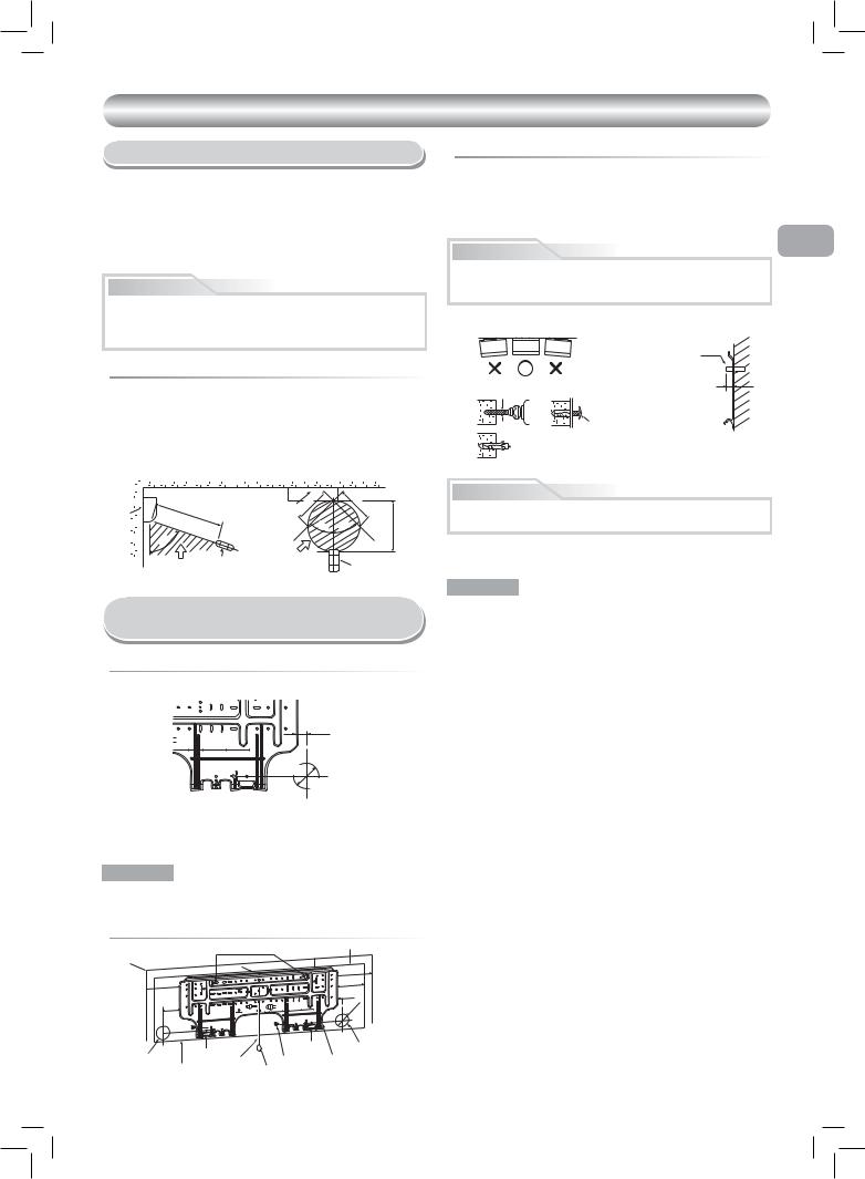
For the rear left and left piping
Wall
Insert the cushion between the indoor unit and wall, and tilt the indoor unit for better operation.
Do not allow the drain hose to get slack.
Cut the piping hole sloped slightly.
Make sure to run the drain hose sloped downward.
The auxiliary piping can be connected to the left, rear left, rear right, right, bottom right or bottom left.
Right
Rear right
Bottom |
Rear |
Left |
|
||
right |
left |
Bottom left |
|
|
Insulate the refrigerant pipes separately with insulation, not together.
8 mm thick heat resisting polyethylene foam
Optional Installation Parts
Part |
|
Parts name |
Q’ty |
|
code |
|
|||
|
|
|
||
|
|
|
||
|
Refrigerant piping |
One |
||
A |
Liquid side |
: dia. 6.35 mm |
||
each |
||||
|
Gas side |
: dia.12.7 mm |
||
|
|
|||
|
|
|
||
B |
Pipe insulating material |
1 |
||
(polyethylene foam, 8 mm thick) |
||||
|
|
|||
|
|
|
|
|
C |
Putty, PVC tapes |
One |
||
each |
||||
|
|
|
||
|
|
|
|
|
Fixing bolt arrangement of outdoor unit
•Secure the outdoor unit with fi xing bolts and nuts if the unit is likely to be exposed to a strong wind.
•Use dia. 8 mm or dia. 10 mm anchor bolts and nuts.
•If it is necessary to drain the defrost water, attach drain nipple 9 and cap water proof ! to the bottom plate of the outdoor unit before installing it.
|
108 mm |
|
|
|
125 mm |
|
28 mm |
|
25 |
mm |
Air inlet |
|
|
|
|
||
|
dia |
. |
|
|
|
|
|
|
|
102 mm |
|
mm |
86 mm |
|
|
|
|
320 |
|
|
|
|
|
|
Air outlet |
|
90 mm |
||
600 mm
Drain outlet
3
1110651101-EN-1.indd 3 |
3/7/08 8:47:14 AM |
INDOOR UNIT
Installation Place
•A place which provides the spaces around the indoor unit as shown in the diagram
•A place where there are no obstacles near the air inlet and outlet
•A place which allows easy installation of the piping to the outdoor unit
•A place which allows the front panel to be opened
•The indoor unit shall be installed as top of the indoor unit comes to at least 2 m height. Also, it must be avoided to put anything on the top of the indoor unit.
CAUTION
•Direct sunlight to the indoor unit’s wireless receiver should be avoided.
•The microprocessor in the indoor unit should not be too close to RF noise sources.
(For details, see the owner’s manual.)
 Remote control
•A place where there are no obstacles such as a curtain that may block the signal from the remote control.
•Do not install the remote control in a place exposed to direct sunlight or close to a heating source such as a stove.
•Keep the remote control at least 1 m apart from the nearest TV set or stereo equipment. (This is necessary to prevent image disturbances or noise interference.)
•The location of the remote control should be determined as shown below.
|
(Side view) |
(Top view) |
|
m |
|
|
5 |
|
unit |
7 m |
|
Indoor unit |
5 |
|
|
m |
|
|
|
|
|
|||||
|
|
|
|
7*m |
||||
Indoor |
|
|
|
|
4 |
|
|
|
|
|
|
|
|
5° |
|
° |
|
|
|
|
|
|
5 |
|||
|
|
|
|
|
|
4 |
|
|
|
° |
|
Reception |
|
|
|
|
|
|
5 |
|
|
|
|
|
||
|
7 |
|
|
|
|
|
|
|
|
Reception |
Remote |
|
range |
|
|
Remote |
|
|
control |
|
|
|
||||
|
|
|
|
|
|
|
||
|
range |
|
|
|
|
|
|
control |
* : Axial distance
Cutting a Hole and Mounting
Installation Plate
 Cutting a hole
When installing the refrigerant pipes from the rear
center e |
from m |
|
hole pipe of |
side right the |
23mm |
|
is edge |
|
|
|
35 |
120 |
180 |
240 |
Pipe hole
dia. 65mm
The center of the pipe hole is above the arrow.
 When the installation plate is directly mounted on the wall
1.Securely fit the installation plate onto the wall by screwing it in the upper and lower parts to hook up the indoor unit.
2.To mount the installation plate on a concrete wall with anchor bolts, use the anchor bolt holes as illustrated in the below figure.
3.Install the installation plate horizontally in the wall.
EN
CAUTION
When installing the installation plate with a mounting screw, do not use the anchor bolt holes. Otherwise, the unit may fall down and result in personal injury and property damage.
Installation plate
(Keep horizontal direction.)
|
Anchor boltt |
5 mm dia. hole |
Projection |
15 mm or less |
7Mounting screw dia. 4 mm x 25R
 Clip anchor (local parts)
CAUTION
Failure to fi rmly install the unit may result in personal injury and property damage if the unit falls.
•In case of block, brick, concrete or similar type walls, make 5 mm dia. holes in the wall.
•Insert clip anchors for appropriate mounting screws 7.
NOTE
•Secure four corners and lower parts of the installation plate with 4 to 6 mounting screws to install it.
1.After determining the pipe hole position on the mounting plate (°), drill the pipe hole (dia. 65 mm) at a slight downward slant to the outdoor side.
NOTE
•When drilling a wall that contains a metal lath, wire lath or metal plate, be sure to use a pipe hole brim ring sold separately.
 Mounting the installation plate
Anchor bolt holes
|
|
|
Hook |
50 |
|
|
|
|
|
|
|
|
|
To unit out line |
|
|
|
|
240mm |
170 |
is |
To unit out line |
|
|
240mm |
|
|
||
|
sideedge |
hole |
To unit out line |
|
|
leftthe |
pipeof |
35mm |
|
85 |
85mmfrom |
thecenter |
To unit out line |
|
|
|
|
120mm |
|
|
Offset |
|
|
|
|
|
|
|
Hook |
Pipe hole |
|
Hook |
Thread |
7 Mounting |
|
|
|||
Indoor unit |
|
Screw |
||
|
|
|
|
Weight |
|
|
40 |
|
ofcenterthe |
thefrom23mm Offset |
170 |
fromfloor |
132 |
|||
hole pipe |
isedgeside right |
23 |
more |
|
|
.65mm |
or |
|
|
dia |
|
|
|
|
2 m |
Pipe hole (dia. 65mm)
1Installation plate
4
1110651101-EN-1.indd 4 |
3/7/08 8:47:16 AM |
 Loading...