


 Loading...
FILE NO. SVM-04031-(1)
AIR-CONDITIONER
UNDER CEILING / CONSOLE TYPE
RAS-18UFHP-ES3 / RAS-18UAH-ES3 RAS-18UFP-ES3 / RAS-18UA-ES3 RAS-24UFHP-ES3 / RAS-24UAH-ES3 RAS-24UFP-ES3 / RAS-24UA-ES3
18 Class |
24 Class |
June 2004
FILE NO. SVM-04031-(1)
CONTENTS
1.SPECIFICATIONS
2.CONSTRUCTION VIEWS
2-1 Indoor Unit
2-2 Outdoor Unit (RAS-18UAH-ES3) 2-3 Outdoor Unit (RAS-18UA-ES3)
2-4 Outdoor Unit (RAS-24UAH-ES3, RAS-24UA-ES3)
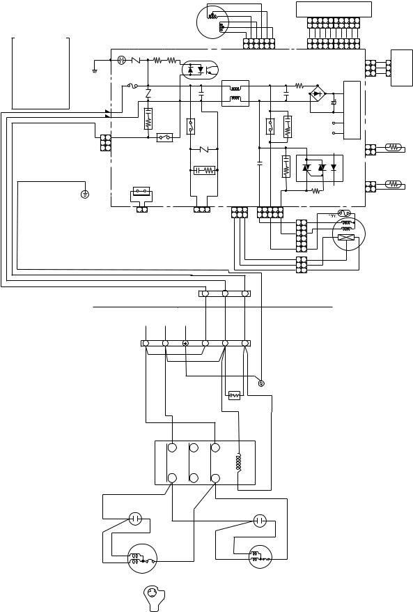
3.WIRING DIAGRAM
3-1 RAS-18UFHP-ES3 / RAS-18UAH-ES3 3-2 RAS-18UFP-ES3 / RAS-18UA-ES3 3-3 RAS-24UFHP-ES3 / RAS-24UAH-ES3 3-4 RAS-24UFP-ES3 / RAS-24UA-ES3
4.SPECIFICATION OF ELECTRICAL PARTS
4-1 Indoor Unit
4-2 Outdoor Unit (RAS-18UAH-ES3) 4-3 Outdoor Unit (RAS-18UA-ES3) 4-4 Outdoor Unit (RAS-24UAH-ES3) 4-5 Outdoor Unit (RAS-24UA-ES3)
5.REFRIGERATION CYCLE DIAGRAM
5-1 RAS-18UFHP-ES3 / RAS-18UAH-ES3 5-2 RAS-18UFP-ES3 / RAS-18UA-ES3 5-3 RAS-24UFHP-ES3 / RAS-24UAH-ES3 5-4 RAS-24UFP-ES3 / RAS-24UA-ES3
6.CONTROL BLOCK DIAGRAM
6-1 RAS-18UFHP-ES3, RAS-24UFHP-ES3 6-2 RAS-18UFP-ES3, RAS-24UFP-ES3
7.OPERATION DESCRIPTION
7-1 Outline of Air Conditioner Control
7-2 Description of Operation Circuit
7-3 Hi POWER Mode
7-4 High-Temperature Limit Control
7-5 Low-Temperature Limit Control
7-6 Defrosting Operation
7-7 Auto Restart Function
7-8 Filter Check Lamp
8.INSTALLATION PROCEDURE
8-1 Safety Cautions
8-2 Installation Diagram of Indoor and Outdoor Units 8-3 Installation
8-4 Indoor Unit
8-5 Outdoor unit
8-6 How to Set Remote Control Selector Switch 8-7 How to Use Drain Pump Kit of Option
8-8 Others
– 1 –

FILE NO. SVM-04031
9.TROUBLESHOOTING CHART
9-1 Troubleshooting Procedure
9-2 Basic Check Items
9-3 Primary Judgement
9-4 Self-Diagnosis by Remote Control (Check Code) 9-5 How to Diagnose Faulty Parts
9-6 Troubleshooting for Indoor Unit
9-7 Troubleshooting for Wiring (Interconnect Cable and Serial Signal Wire) 9-8 Troubleshooting for P.C. Board
9-9 Troubleshooting for Remote Control
10.PARTS REPLACEMENT
10-1 Indoor Unit
10-2 Outdoor Unit (RAS-18UAH-ES3, RAS-18UA-ES3) 10-3 Outdoor Unit (RAS-24UAH-ES3, RAS-24UA-ES3)
11.EXPLODED VIEWS AND PARTS LIST
11-1 Indoor Unit (E-Parts Assy)
11-2 |
Indoor Unit |
11-3 Outdoor Unit (RAS-18UAH-ES3) |
|
11-4 |
Outdoor Unit (RAS-18UA-ES3) |
11-5 |
Outdoor Unit (RAS-24UAH-ES3) |
11-6 |
Outdoor Unit (RAS-24UA-ES3) |
•This air conditioner is charged with HFC (R-410A) that does not deplete the Ozone layer.
•This air conditioner requires special service tools
for the refrigerant R-410A.
– 2 –

FILE NO. SVM-04031
1. SPECIFICATIONS
|
MODEL |
|
RAS-18UFHP-ES3 |
|
RAS-18UFP-ES3 |
|
RAS-24UFHP-ES3 |
|
RAS-24UFP-ES3 |
||||||
|
|
|
|
RAS-18UAH-ES3 |
|
RAS-18UA-ES3 |
|
RAS-24UAH-ES3 |
|
RAS-24UA-ES3 |
|||||
ITEM |
|
|
Cooling |
Heating |
Cooling |
Cooling |
Heating |
Cooling |
|||||||
Capacity |
|
|
220V |
240V |
220V |
240V |
220V |
240V |
220V |
240V |
220V |
240V |
220V |
240V |
|
|
|
kW |
5.00 |
5.10 |
5.70 |
5.75 |
5.30 |
5.35 |
6.20 |
6.30 |
7.00 |
7.10 |
6.80 |
6.85 |
|
|
Phase |
|
|
|
|
|
1 |
|
|
|
|
|
|||
Power source |
|
V |
|
|
|
|
|
220 − 240 |
|
|
|
|
|
||
|
|
Hz |
|
|
|
|
|
50 |
|
|
|
|
|
|
|
Power consumption |
|
W |
1960 |
2010 |
1830 |
1880 |
1950 |
2040 |
2515 |
2570 |
2430 |
2530 |
2640 |
2790 |
|
Power factor |
|
% |
98 |
96 |
98 |
96 |
97 |
92 |
96 |
92 |
96 |
91 |
95 |
91 |
|
Running current |
Indoor |
A |
|
|
0.4 |
|
|
|
|
|
0.45 |
|
|
||
Outdoor |
A |
8.60 |
8.30 |
7.70 |
7.60 |
8.60 |
8.80 |
11.35 |
11.20 |
11.10 |
11.15 |
12.15 |
12.35 |
||
|
|||||||||||||||
Starting current |
|
A |
|
|
47 |
|
|
33 |
|
|
54 |
|
|
|
|
Moisture removal |
|
lit/h |
|
|
2.0 |
|
|
|
|
2.5 |
|
|
2.7 |
||
Noise |
Indoor (H/M/L) |
db |
|
|
43/39/36 |
|
|
|
|
46/42/37 |
|
|
|||
Outdoor |
db |
51 |
52 |
52 |
53 |
51 |
52 |
56 |
57 |
57 |
58 |
56 |
57 |
||
|
|||||||||||||||
Refrigerant |
Name of refrigerant |
|
|
|
|
|
R-410A |
|
|
|
|
|
|||
Rated amount |
kg |
|
|
1.3 |
|
|
1.14 |
|
|
1.6 |
|
|
|||
|
|
|
|
|
|
|
|
|
|||||||
Refrigerant control |
|
|
|
|
|
|
|
Capillary tube |
|
|
|
|
|
||
|
Gas side size |
mm |
|
|
|
|
|
12.70 |
|
|
|
|
|
||
|
Connection type |
|
|
|
|
|
Flare connection |
|
|
|
|
|
|||
|
|
|
|
|
|
|
|
|
|
|
|
||||
|
Liquid side size |
mm |
|
|
|
|
|
6.35 |
|
|
|
|
|
||
Interconnection |
Connection type |
|
|
|
|
|
Flare connection |
|
|
|
|
|
|||
|
|
|
|
|
|
|
|
|
|
|
|||||
pipe |
Maximum length |
m |
|
|
|
|
|
15*1 |
|
|
|
|
|
||
|
(One way) |
|
|
20*2 |
|
|
|
|
25*2 |
|
|
||||
|
|
|
|
|
|
|
|
|
|
||||||
|
Maximum height |
m |
|
|
8 |
|
|
|
|
|
10 |
|
|
|
|
|
difference |
|
|
|
|
|
|
|
|
|
|
||||
|
|
|
|
|
|
|
|
|
|
|
|
|
|
||
INDOOR UNIT |
|
|
|
RAS-18UFHP-ES3 |
|
RAS-18UFP-ES3 |
RAS-24UFHP-ES3 |
|
RAS-24UFP-ES3 |
||||||
|
Width |
mm |
|
|
|
|
|
1093 |
|
|
|
|
|
||
Dimensions |
Height |
mm |
|
|
|
|
|
633 |
|
|
|
|
|
||
|
Depth |
mm |
|
|
|
|
|
208 |
|
|
|
|
|
||
Net weight |
|
kg |
|
|
|
|
|
23 |
|
|
|
|
|
|
|
Evaporator type |
|
|
|
|
|
|
|
Finned tube |
|
|
|
|
|
||
Indoor fan type |
|
|
|
|
|
|
|
Multi blade fan |
|
|
|
|
|
||
|
High fan |
m3/h |
800 |
830 |
800 |
900 |
930 |
900 |
|||||||
Air volume |
Medium fan |
m3/h |
680 |
700 |
680 |
750 |
760 |
750 |
|||||||
|
Low fan |
m3/h |
580 |
650 |
580 |
550 |
660 |
650 |
|||||||
Fan motor output |
|
W |
|
|
|
|
|
50 |
|
|
|
|
|
|
|
Air filter |
|
|
|
|
|
|
|
Washable -filter |
|
|
|
|
|
||
OUTDOOR UNIT |
|
|
|
RAS-18UAH-ES3 |
|
RAS-18UA-ES3 |
|
RAS-24UAH-ES3 |
|
RAS-24UA-ES3 |
|||||
|
Width |
mm |
|
|
830 |
|
|
|
|
880 |
|
|
|||
Dimensions |
Height |
mm |
|
|
538 |
|
|
|
|
690 |
|
|
|||
|
Depth |
mm |
|
|
300 |
|
|
|
|
310 |
|
|
|||
Net weight |
|
kg |
|
|
50 |
|
|
41 |
|
|
67 |
|
|
63 |
|
Condenser type |
|
|
|
|
|
|
|
Finned tube |
|
|
|
|
|
||
Outdoor fan type |
|
|
|
|
|
|
|
Propeller fan |
|
|
|
|
|
||
Airflow volume |
|
m3/h |
2105 |
2310 |
2150 |
2310 |
1830 |
2010 |
3380 |
3560 |
3380 |
3560 |
3380 |
3560 |
|
Fan motor output |
|
W |
|
|
42 |
|
|
|
|
|
65 |
|
|
|
|
Compressor |
Model |
|
|
PA225X3F-4L |
|
5KS225DAA |
|
PA290X3F-4MS |
|
5JS315DAG01 |
|||||
Output |
W |
|
|
1500 |
|
|
|
|
2200 |
|
|
||||
|
|
|
|
|
|
|
|
|
|||||||
Safety device |
|
|
|
IOL, Td Sensor |
|
IOL |
|
IOL, Td Sensor |
|
|
IOL |
||||
Louver type |
|
|
|
|
|
|
|
Automatic louver |
|
|
|
|
|
||
Usable outdoor temperature range°C |
|
15 ~ 43 |
−10 ~ 24 |
15 ~ 43 |
15 ~ 43 |
−10 ~ 24 |
15 ~ 43 |
||||||||
|
|
|
|
|
– 3 – |
|
|
|
|
|
|
|
|
||
FILE NO. SVM-04031
Note : 1
• Capacity is based on the following temperature conditions.
Condition |
|
JIS C9612-1994 |
|
|
|
Temperature |
Cooling |
Heating |
(DB) |
27°C |
20°C |
Indoor unit inlet air temperature |
|
|
(WB) |
19°C |
12°C |
(DB) |
35°C |
7°C |
Outdoor unit inlet air temperature |
|
|
(WB) |
24°C |
6°C |
Note : 2
• Charge refrigerant according to the table below.
|
Refrigerant |
RAS-18UFHP-ES3 / RAS-18UAH-ES3 |
RAS-24UFHP-ES3 / RAS-24UAH-ES3 |
|
RAS-18UFP-ES3 / RAS-18UA-ES3 |
RAS-24UFP-ES3 / RAS-24UA-ES3 |
|
|
|
||
|
|
|
|
*1 |
No need to charge |
15m or less |
15m or less |
|
refrigerant |
||
|
|
|
|
|
|
|
|
*2 |
Need to charge |
Over 15m up to 20m (20g/m) |
Over 15m up to 25m (30g/m) |
|
refrigerant |
||
|
|
|
|
|
|
|
|
– 4 –
FILE NO. SVM-04031
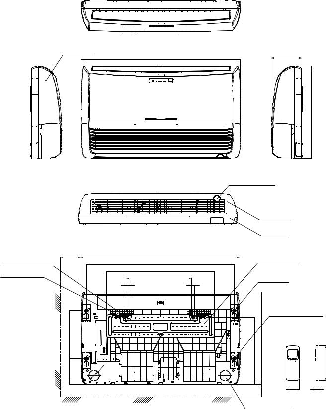
2. CONSTRUCTION VIEWS
2-1. Indoor Unit
Front panel
1093
UNDER CEILING & CONSOLE INSTALLATION
For stud bolt |
200 Min |
1093 |
( 8 - 10) |
|
1015 |
For stud bolt ( |
6) |
742 |
450 |
||
|
20 |
20 |
330 |
|
|
165 |
|
74 |
|
||
|
|
208
633
Knock out system
Grille air inlet
Back Body
Installation plate
Mount plate
|
M10 Suspention bolt |
||
633 |
|
|
|
460 |
|
160 |
|
|
|
||
70 Min |
57 |
18 |
|
Wireless remote control |
|||
|
|||
Knock out system
– 5 –
|
A Detail Drawing |
|
A |
120 |
|
|
|
|
|
||
|
600 |
|
|
|
|
|
50 |
R10 |
|
|
|
|
35 |
|
|
|
|
|
|
|
|
|
|
|
|
23 |
325 |
52 |
|
|
6 hole |
|
|
|
|
11x14 hole |
|
|
|
|
|
|
Handle |
|
420 |
6 – |
538 |
– |
|
|
300 |
Fan guard |
25 Drain outlet |
90 |
600 |
|
830 |
Installation dimension
100 or more |
|
600 |
|
|
|
Air inlet |
|
|
|
|
|
600 or more |
||
|
Air inlet |
|
||
325 |
|
|
|
|
|
600 or |
|
|
|
100 or more |
|
4x |
11x14 |
|
Air |
more |
|||
|
|
for |
8- 10 |
|
|
outlet |
|
anchor bolt |
|
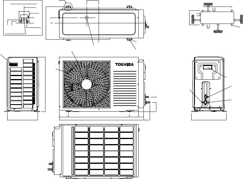
8- 6 holes
(for fixing outdoor unit)
6- 11x14 holes
or 8 — 10 anchor bolt)
|
|
|
|
|
Electric |
|
|
|
|
|
|
Parts cover |
|
|
|
|
|
Service Port |
Liquid side |
|
|
|
|
|
(Flare |
6.35) |
|
|
|
|
|
|
||
|
|
|
54 |
|
Gas side |
|
|
|
|
|
(Flare |
12.7) |
|
|
|
|
91 |
|
||
|
|
|
|
|
|
|
90 |
50 |
60 |
|
|
344 |
|
ES3)-18UAH-(RAS Unit Outdoor .2-2
(1)-04031-SVM .NO FILE
– 7 –
A |
Detail Drawing |
|
|
50 |
600 |
|
R10 |
|
|
35 |
|
|
|
|
325 301 |
|
23 |
|
6 hole |
|
11x14 hole
Handle
538
300
A
120
325 |
52.5 |
25Drain outlet |
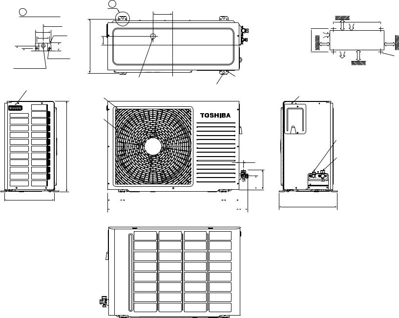
4- 11x14 hole |
8- 6 hole |
(for fixing outdoor unit) |
||
|
(for Ø8-Ø10 anchor bolt) |
|
Fan guard
420
27  100 130
|
|
|
|
|
|
|
|
|
|
|
|
|
90 |
|
|
600 |
|
|
90 |
|
|
||||
|
|
|
||||||||||
|
|
|
780 |
|
|
|
|
|
|
65.5 |
||
|
|
|
|
|
|
|
|
|
||||
|
|
|
|
|
|
|
|
|
|
|
|
|
|
|
|
|
|
|
|
|
|
|
|
|
|
Installation dimension |
|
|
||
100 or more |
|
600 |
|
|
|
Air inlet |
|
|
|
|
|
600 or more |
||
|
Air inlet |
|
||
325 |
|
|
|
|
|
600 or |
|
|
|
100 or more |
|
4x |
11x14 |
|
Air |
more |
|||
|
|
or |
8- 10 |
|
|
outlet |
|
anchor bolt |
|
Electric parts cover
Liquid side (Flare 6.35)
Gas side (Flare 12.7)
 Service
Port
344
ES3)-18UA-(RAS Unit Outdoor .3-2
(1)-04031-SVM .NO FILE

FILE NO. SVM-04031-(1)
2-4. Outdoor Unit (RAS-24UAH-ES3, RAS-24UA-ES3)
dimensionInstallation 600 600 or more |
inletAir |
12X18 8 10 bolt |
310 |
|
600or outletAir |
anchor |
|||
|
|
4 - for |
|
|
|
|
more |
|
|
100 or more |
|
100 or more |
|
23 |
|
340 |
|
|
|
|
6852 |
outlet |
140 |
25 Drain |
|
|
600 |
120 |
A |
8.63 |
340 |
Electric Parts cover |
Liquid side (Flare 6.35) |
Gas side (Flare 1 2.7) |
Service Port |
12 |
|
|
|
|
340 (pitch) |
364 |
|
|
|
|
|
12 |
|
|
Handle |
|
88 |
74 |
|
|
|
|
|
|
|
|
|
|
|
880 |
|
|
690 |
|
|
|
Handle |
|
|
|
|
|
|
Detail Drawing |
600 50 |
A |
|
27
hole12x18
340
– 8 –

|
|
|
|
|
|
|
|
|
|
|
|
|
|
|
|
FILE NO. SVM-04031-(1) |
|||||||||
|
|
|
|
|
3. WIRING DIAGRAM |
|
|
|
|
|
|
|
|
|
|
|
|
||||||||
3-1. RAS-18UFHP-ES3 / RAS-18UAH-ES3 |
|
|
|
|
|
|
|
|
|
|
|
|
|
|
|
|
|
||||||||
|
|
|
|
|
|
|
|
|
|
|
|
ORN |
|
|
|
|
|
|
|
|
|
|
|
|
|
|
|
|
|
|
|
|
|
|
|
|
|
RED |
|
|
|
|
INFRARED RA |
YS RECEIVE |
|
|
|
|
|||
|
|
|
|
|
|
|
|
|
|
|
|
|
|
|
|
AND INDICA TION P AR TS |
|
|
|
|
|||||
|
|
|
|
|
|
|
|
LOUVER |
|
|
|
PNK |
|
|
|
|
|
|
|
|
|||||
|
|
|
|
|
|
|
|
|
|
|
|
|
|
|
|
|
|
|
|
|
|
|
|||
|
|
|
|
|
|
|
|
|
|
|
YEL |
|
|
|
|
|
1 2 |
3 4 5 |
6 7 8 |
9 10 |
|
|
|
|
|
|
|
|
|
|
|
|
|
MOT OR |
|
|
|
|
|
|
|
CN25 |
|
|
|
|
|||||
|
|
|
|
|
|
|
|
|
|
|
|
BR W |
|
|
|
1 2 3 4 5 6 7 8 9 10 |
|
|
|
|
|||||
|
|
|
|
|
|
|
|
|
|
|
|
|
|
|
|
|
|
|
|
||||||
|
|
|
|
|
|
|
|
|
|
|
|
BLU |
|
|
|
|
|
BLU BLU |
BLU BLU BLU BLU |
BLU BLU BLU WHI |
|
|
|
|
|
COLOR IDENTIFICA |
TION |
|
|
|
|
|
|
|
|
|
|
|
|
|
|
|
|
|
|
||||||
|
|
|
|
|
|
|
|
|
6 5 |
4 3 2 |
1 |
|
|
1 2 |
3 4 5 |
6 7 8 |
9 10 |
|
|
|
|
||||
BR W |
: |
BROWN |
|
|
|
|
|
|
|
CN07 |
|
CN13 |
|
|
|
|
|||||||||
|
|
|
|
|
|
|
6 5 |
4 3 2 |
1 |
|
1 2 |
3 4 5 |
6 7 8 |
9 10 |
|
|
|
|
|||||||
|
|
|
|
|
|
|
|
|
|
|
|
|
|||||||||||||
RED |
: |
RED |
|
|
SG01 |
|
R09 |
R507 |
|
|
|
|
|
|
|
|
|
|
|
|
|
|
|
|
|
WHI |
: |
WHITE |
|
|
|
|
|
|
|
|
|
|
|
|
|
|
CN100 |
CN101 |
SWITCH |
||||||
|
BLK |
|
|
|
IC04 |
|
|
|
|
|
|
|
|
|
|
|
|||||||||
YEL |
: |
YELLOW |
|
P04 |
|
|
|
|
|
|
|
|
MAIN PCB |
|
|
|
1 |
1 |
WHI |
1 |
PCB |
||||
BLU |
: |
BLUE |
|
R22 |
|
|
|
|
|
|
|
MCC-865A |
|
|
|
GRY |
|
||||||||
|
|
|
|
|
|
|
|
|
|
|
|
2 |
2 |
2 |
|
||||||||||
BLK |
: |
BLACK |
|
F01 |
FUSE |
|
|
|
|
|
|
|
|
|
|
|
|
|
|
3 |
3 |
GRY |
3 |
|
|
GR Y |
: |
GRA Y |
|
|
|
|
|
L01 |
|
|
|
|
R01 |
|
|
|
|
|
|
|
MCC-865B |
||||
PNK |
: |
PINK |
|
T6.3A |
250V AC |
|
|
|
|
|
|
|
|
DB01 |
|
|
|
|
|
||||||
|
|
|
|
|
|
|
|
|
|
|
|
|
|
|
|
|
|||||||||
ORN |
: |
ORANGE |
|
|
|
|
|
|
|
|
|
|
|
|
|
|
|
|
|
|
|
|
|||
|
|
|
|
|
|
|
|
|
|
|
|
|
|
|
|
|
|
|
|
|
|
||||
GRN&YEL |
: |
GREEN& |
|
|
|
R21 |
|
C15 |
|
|
|
|
|
|
|
C01 |
|
|
|
|
|
|
|
|
|
|
|
YELLOW |
|
|
|
|
|
|
|
|
|
|
|
|
|
|
|
|
|
|
|
||||
|
|
|
|
|
|
|
|
|
|
|
|
|
|
|
|
|
|
SUPPLYPOWER CIRCUIT |
|
|
|
|
|||
GRN |
: |
GREEN |
|
|
|
|
|
|
|
|
|
|
|
|
|
|
|
C02 |
|
|
|
|
|||
PUR |
: |
PURPLE |
|
CN30 |
|
|
|
|
|
|
|
|
|
|
|
|
|
|
|
|
|
|
|
||
BLK |
|
|
|
|
|
|
|
|
|
|
|
|
|
|
|
|
|
|
|
|
|||||
|
|
|
|
|
|
|
|
|
|
|
|
|
|
|
|
|
|
|
|
|
|
|
|
|
|
|
|
|
|
WHI |
CN31 |
|
|
|
R Y401 |
|
|
|
|
|
R Y501 |
CR502 |
|
|
|
|
|
|
|
||
|
|
|
|
RED |
|
|
|
|
|
|
|
|
|
|
|
|
|
|
|
|
|
|
|
||
|
|
|
|
|
|
|
|
|
|
|
|
|
|
|
|
|
|
DC12V |
|
|
|
|
|
|
|
|
|
|
|
|
|
|
|
|
|
|
|
|
|
|
|
|
|
|
|
|
|
|
|
|
|
|
|
|
|
|
|
|
|
|
|
|
|
|
|
|
|
|
|
|
|
|
|
|
|
THERMO |
|
|
|
|
|
|
|
|
|
|
|
|
|
|
|
|
|
|
|
|
DC5V |
|
|
|
|
SENSOR |
|
|
|
|
|
|
|
|
|
|
|
|
|
|
|
|
|
|
|
|
|
|
CN03 |
|
(TA) |
||
|
|
|
|
|
|
|
|
|
R405 |
|
|
|
|
|
|
|
|
|
|
|
BLK |
|
|
||
|
|
|
|
|
|
|
|
|
|
|
|
|
|
|
|
|
|
|
|
1 |
1 |
|
|
||
|
|
|
|
|
|
|
|
|
|
|
|
|
|
|
|
|
|
|
|
|
|
|
|||
|
|
|
|
|
|
|
|
|
|
|
|
|
|
|
|
|
CR501 |
|
IC03 |
|
2 |
2 |
BLK |
|
|
|
|
|
|
|
|
|
|
|
CR401 |
|
|
|
C501 |
|
|
|
|
|
|
|
|
|
HEAT |
||
|
|
|
|
|
CN23 |
|
|
|
|
|
|
|
|
|
|
|
|
|
|
|
|
|
|||
|
|
|
|
|
|
|
|
|
|
|
|
|
|
|
|
|
|
|
|
|
|
|
EXCHANGER |
||
|
|
|
|
|
|
|
|
|
|
|
|
|
|
|
|
|
|
|
|
|
|
|
|
SENSOR |
|
|
|
|
|
GRN&YEL |
|
|
|
|
|
|
|
|
|
|
|
|
|
|
|
|
CN01 |
BLK |
(TC) |
|
|
|
|
|
|
|
|
J401 |
|
|
|
|
|
|
|
|
|
|
|
|
|
|
1 |
1 |
|
|
|
|
|
|
|
|
|
|
|
|
|
|
|
|
|
|
|
|
|
|
|
|
2 |
2 |
BLK |
|
|
|
|
|
|
|
|
|
|
|
|
|
|
|
|
|
|
|
|
R506 |
|
|
|
|
|
|
|
|
|
|
|
|
|
2 1 |
CN402 |
CN401 |
1 2 3 |
CN1 1 |
1 2 |
3 |
5 |
3 |
1 |
CN10 |
|
BLK |
|
|
|
|
|
|
|
|
|
|
|
|
FOR FLOA |
T SWITCH |
FOR DRAIN PUMP |
|
1 |
2 |
3 |
5 |
3 |
1 |
|
|
|
|
|
|
|
|
|
||
|
|
|
|
|
|
|
|
|
|
|
|
WHI 1 |
1 |
WHI |
|
|
|
|
|
|
|||||
|
|
|
|
|
|
(OPTION) |
|
(OPTION) |
|
|
|
|
|
|
|
|
|
|
|
|
|
||||
|
|
|
|
|
When you use float |
|
|
|
|
|
|
|
|
|
RED |
|
RED |
|
|
FAN |
|
|
|||
|
|
|
|
|
|
|
|
|
|
|
|
|
|
3 |
|
|
|
MOTOR |
|
|
|||||
|
|
|
|
|
switch you should |
|
|
|
|
|
|
|
|
|
3 |
PUR |
|
|
|
|
|||||
|
|
|
|
|
|
|
|
|
|
|
|
|
|
|
|
|
|
|
|
|
|
|
|||
|
|
|
|
|
|
cut J401 |
|
|
|
|
|
|
|
|
BLK |
|
|
|
|
|
|
|
|
|
|
|
|
|
|
|
|
|
|
|
|
|
|
|
|
|
|
6 |
6 |
|
|
|
|
|
|
|
|
|
|
|
|
|
|
|
|
|
|
|
|
|
|
|
|
|
|
|
|
|
|
|
|
||
BR W |
3 |
3 |
BLU |
|
GR Y |
|
|||
2 |
2 |
|
||
YEL |
GR Y |
|||
1 |
1 |
|||
|
|
INDOOR |
1 |
2 |
3 |
INDOOR |
|
|
TERMINAL |
|
|
||||
|
|
|
UNIT |
|
MAIN P.C. BOARD (MCC-890) |
|
BLOCK |
|
|
|
TRANSFORMER |
||
|
|
|
|
|
|
|
|
|
|
|
|
|
|
|
OUTDOOR |
BLK 1 |
1 |
|
|
|
|
|
DISCHARGE |
||
|
|
POWER SUPPLY |
|
|
|
UNIT |
BLK |
|
2 |
CN06 |
|
|
|
|
|||||
|
|
220-240 V~ 50 Hz |
|
|
|
|
3 3 |
|
|
|
|
|
PIPE |
||||||
|
|
|
|
|
|
|
|
|
|
|
|
|
|
SENSOR (TD) |
|||||
|
|
|
|
|
|
|
|
|
|
RED |
|
|
|
|
|
|
|
||
|
|
|
|
|
|
|
|
|
|
1 |
1 |
CN05 |
|
|
|
1 |
1 |
BLU |
|
|
OUTDOOR |
|
|
|
|
|
|
|
|
|
|
|
|
|
CN07 |
|
|||
|
|
|
|
|
|
|
|
|
RED |
3 3 |
|
|
2 |
|
|
||||
|
TERMINAL |
L |
|
N |
i |
1 |
2 |
3 |
GRN&YEL |
|
|
|
SG01 |
TNR |
|
|
3 |
3 |
BLU |
|
BLOCK |
|
|
FERRITE CORE |
|
|
BLK |
|
|
R74 |
|
|
|
|
|
||||
|
|
|
|
|
|
|
1 1 |
|
|
|
|
|
|
||||||
|
|
|
BLK |
|
|
|
|
|
|
|
|
|
|
|
|
|
|||
|
|
|
|
|
|
|
|
|
BLK |
|
|
F01 |
|
|
|
|
|
||
|
|
|
|
RED |
|
|
|
|
3 3 |
|
|
|
|
|
|||||
|
|
|
|
GRN&YEL |
|
|
250VAC T6. 3A |
TNR |
|
1 1 |
BLK |
||||||||
|
|
|
|
|
|
|
|
WHI |
|
|
|
||||||||
|
|
|
|
|
|
|
|
|
|
5 5 |
|
|
R73 |
CN08 2 |
|
|
|||
|
|
|
|
|
|
|
|
|
|
RED 7 |
7 |
CN01 |
|
|
|
3 |
3 |
BLK |
|
|
|
|
|
|
|
|
|
|
CHASSIS |
GRY 9 9 |
|
|
|
|
|
HEAT |
|||
|
BLK |
|
RED |
|
|
|
|
|
|
|
|
|
EXCHANGER |
||||||
|
|
|
|
|
|
|
|
|
|
|
|
||||||||
|
|
|
|
|
|
|
|
|
|
|
|
|
|
|
SENSOR (TE) |
||||
|
|
|
|
|
|
|
|
|
|
|
|
|
|
|
|
|
|
||
|
|
|
|
|
MAGNETIC |
|
|
|
|
|
|
|
|
RY07 |
|
|
|
|
|
|
|
|
|
|
|
|
|
|
|
|
|
|
|
|
|
|
|
||
|
|
|
|
|
CONTACTOR |
|
|
|
BLU 1 1 |
|
|
|
|
|
|
|
|||
|
|
|
|
|
|
|
|
|
|
CN11 |
|
|
|
|
|
|
|||
|
|
|
|
R |
S |
T |
|
|
|
|
3 3 |
|
|
|
|
|
|
||
|
|
|
|
A1 |
|
|
YEL |
|
|
|
|
|
|
|
|||||
|
|
|
|
|
|
|
|
CR11 |
RY05 |
|
|
|
|
||||||
|
|
|
|
|
|
|
52C |
|
|
|
|
|
|
|
|
|
|
|
|
|
|
|
|
|
|
|
|
|
BLU 1 1 |
|
|
|
|
|
|
|
|||
|
|
|
|
U |
V |
W |
A2 |
|
|
CN02 |
|
|
|
|
|
|
|||
|
|
|
|
|
|
|
|
3 3 |
|
|
|
|
|
|
|||||
|
|
|
|
|
|
|
BLU |
|
CR12 |
|
|
|
|
|
|||||
|
|
|
|
|
|
|
|
|
|
COIL FOR |
|
|
|
|
|
|
|
|
|
|
|
|
|
|
|
|
|
|
|
|
|
|
|
|
|
|
|
|
|
|
|
|
|
|
|
|
|
|
|
4 WAY VALVE |
|
|
CR13 |
|
|
|
|
|
|
|
|
|
|
|
|
|
|
|
|
|
|
|
|
RY06 |
|
|
|
||
|
|
|
|
|
|
|
|
|
|
|
|
|
|
|
|
|
|
|
|
|
|
|
|
CAPACITOR |
|
|
|
CAPACITOR |
|
|
|
|
|
|
|
|
|
|
|
|
|
RED |
|
|
|
|
RED |
|
|
|
|
|
|
|
|
|
|
|
|
|
|
|
|
|
|
|
|
|
|
|
|
|
|
CN03 |
|
|
|
|
|
|
|
|
|
|
|
|
|
|
|
|
|
|
|
1 |
3 |
|
|
|
|
|
C |
|
WHI |
S |
|
|
|
WHI |
|
|
|
|
|
1 |
|
|
|
|
|
|
|
|
C |
|
|
|
|
|
|
|
|
|
|
|
|
|
|||
|
|
|
|
BLK |
|
BLK |
|
|
|
|
BLK |
|
|
|
|
|
|||
S |
R |
|
PNK |
|
|
RED |
|
|
|
|
|
|
|
|
|
||||
|
|
|
|
|
|
|
|
|
|
|
|
|
|||||||
COMPRESSOR TERMINAL |
|
|
R |
|
|
|
|
|
|
|
|
|
|
|
|
|
|
|
|
|
|
|
|
|
|
|
FAN MOTOR |
|
|
|
|
|
|
|
|
|
|
||
|
|
|
COMPRESSOR |
|
|
|
|
|
|
|
|
|
|
|
|
|
|||
−9 −
FILE NO. SVM-04031-(1)
3-2. RAS-24UFHP-ES3 / RAS-24UAH-ES3
COLOR IDENTIFICA TION
BR W |
: |
BROWN |
RED |
: |
RED |
WHI |
: |
WHITE |
YEL |
: |
YELLOW |
BLU |
: |
BLUE |
BLK |
: |
BLACK |
GR Y |
: |
GRA Y |
PNK |
: |
PINK |
ORN |
: |
ORANGE |
GRN&YEL |
: |
GREEN& |
|
|
YELLOW |
GRN |
: |
GREEN |
PUR |
: |
PURPLE |
|
ORN |
|
|
|
|
|
|
|
|
|
|
|
|
|
|
|
|
|
|
RED |
|
|
|
|
|
|
|
INFRARED RA |
|
YS RECEIVE |
|||||||
|
|
|
|
|
|
|
|
AND INDICA TION P AR TS |
||||||||||
LOUVER |
PNK |
|
|
|
|
|
|
|
||||||||||
|
|
|
|
|
|
|
|
|
|
|
|
|
|
|
|
|
||
YEL |
|
|
|
|
|
|
|
1 |
2 |
3 4 |
5 |
|
6 7 |
8 |
9 10 |
|||
MOT OR |
|
|
|
|
|
|
CN25 |
|
||||||||||
|
BR W |
|
|
|
|
|
1 |
2 |
3 4 |
5 |
6 7 |
8 |
9 10 |
|||||
|
|
|
|
|
|
|
||||||||||||
|
BLU |
|
|
|
|
|
|
|
BLU BLU |
BLU BLU BLU BLU |
BLU BLU BLU WHI |
|||||||
|
|
|
|
|
|
|
|
|
||||||||||
|
CN07 |
6 5 |
4 3 2 |
1 |
CN13 |
1 2 |
3 4 5 |
|
6 7 8 |
9 10 |
||||||||
|
6 |
5 |
4 |
3 |
2 |
1 |
1 |
2 |
3 |
4 |
5 |
|
6 |
7 |
8 |
9 10 |
||
|
|
|
||||||||||||||||
|
SG01 |
|
R09 |
R507 |
|
|
|
|
|
|
|
|
|
|
|
|
BLK |
|
|
|
IC04 |
|
|
|
|
MAIN PCB |
|
|
|||
|
P04 |
R22 |
|
|
|
|
|
|
|
|
|
||||
|
|
|
|
|
|
|
|
MCC-865A |
|
|
|||||
|
|
|
|
|
|
|
|
|
|
|
|||||
|
|
|
|
|
|
|
|
|
|
|
|
||||
|
F01 |
FUSE |
|
|
|
|
L01 |
|
|
|
|
|
|
|
|
|
T6.3A |
250V AC |
|
|
|
|
|
|
|
|
|
R01 |
|
||
|
|
|
|
|
|
|
|
|
|
|
|
|
|||
|
|
|
R21 |
|
C15 |
|
|
|
|
|
|
|
C01 |
|
|
BLK |
CN30 |
|
|
|
|
|
|
|
|
|
|
|
|
|
|
|
|
|
|
|
|
|
|
|
|
|
|
|
|
|
|
WHI |
CN31 |
|
|
|
R Y401 |
|
|
|
|
|
R Y501 |
CR502 |
|||
RED |
|
|
|
|
|
|
|
|
|
|
|
|
|||
|
|
|
|
|
|
|
|
|
|
|
|
|
|
|
|
|
|
|
|
|
R405 |
|
|
|
|
|
|
|
|
|
|
|
|
|
|
|
|
|
|
|
|
|
|
|
CR501 |
|
|
|
|
|
|
|
CR401 |
|
|
|
|
C501 |
|
|
|
|
|
|
CN23 |
|
|
|
|
|
|
|
|
|
|
|
|
|
|
|
|
|
|
|
|
|
|
|
|
|
|
|
|
|
|
GRN&YEL |
|
|
|
|
|
|
|
|
|
|
|
|
|
|
|
|
|
J401 |
|
|
|
|
|
|
|
|
|
|
|
|
|
|
|
2 1 |
CN402 |
CN401 |
1 2 3 |
CN1 1 |
1 2 |
3 |
5 |
3 |
1 |
CN10 |
|
|
|
|
FOR FLOA |
T SWITCH |
FOR DRAIN PUMP |
|
1 |
2 |
3 |
5 |
3 |
1 |
|
|
|
||
|
|
|
|
|
|
|
|
WHI |
1 |
1 |
|||||
|
|
(OPTION) |
|
(OPTION) |
|
|
|
|
|
|
|
||||
|
When you use float |
|
|
|
|
|
|
|
|
|
RED |
3 |
3 |
||
|
switch you should |
|
|
|
|
|
|
|
|
|
|
||||
|
|
|
|
|
|
|
|
|
|
|
|
|
|||
|
|
cut J401 |
|
|
|
|
|
|
|
|
BLK |
|
|
|
|
|
|
|
|
|
|
|
|
|
|
|
|
|
6 |
6 |
|
|
|
|
|
|
|
|
|
|
|
|
|
|
|
||
|
|
|
|
|
|
|
|
|
|
BR W |
|
|
|
3 |
3 |
|
|
|
|
|
|
|
|
|
|
GR Y |
|
|
|
||
|
|
|
|
|
|
|
|
|
|
|
|
|
2 |
2 |
|
|
|
|
|
|
|
|
|
|
|
YEL |
|
|
|
||
|
|
|
|
|
|
|
|
|
|
|
|
|
1 |
1 |
|
|
|
|
|
|
|
|
|
|
|
|
|
|
|
||
DB01 |
|
|
C02 |
POWER SUPPLY |
|
DC12V |
CIRCUIT |
|
|
||
DC5V |
|
|
IC03 |
|
|
CN100 |
CN101 |
SWITCH |
||
1 |
1 |
WHI 1 |
||
PCB |
||||
2 |
2 |
GR Y 2 |
|
|
3 |
3 |
GR Y 3 |
|
|
MCC-865B
|
THERMO |
|
SENSOR |
CN03 |
(TA) |
|
1 1 BLK
2 2 BLK
HEAT
EXCHANGER
SENSOR
CN01 (TC)
1 1 BLK 2 2 BLK
R506
BLK |
|
WHI |
|
RED |
FAN |
PUR |
MOTOR |
|
|
BLU |
|
GR Y |
|
INDOOR |
1 |
2 |
3 |
INDOOR |
|
|
TERMINAL |
|
|
||||
|
|
|
UNIT |
|
MAIN P.C. BOARD (MCC-890) |
|
BLOCK |
|
|
|
TRANSFORMER |
||
|
|
|
|
|
|
|
|
|
|
|
|
|
|
|
|
OUTDOOR |
BLK 1 |
1 |
|
|
|
|
|
DISCHARGE |
||
|
|
POWER SUPPLY |
|
|
|
|
UNIT |
BLK |
|
2 |
CN06 |
|
|
|
|
|||||
|
|
220-240 V~ 50 Hz |
|
|
|
|
|
3 3 |
|
|
|
|
|
PIPE |
||||||
|
|
|
|
|
|
|
|
|
|
|
|
|
|
|
SENSOR (TD) |
|||||
|
|
|
|
|
|
|
|
|
|
|
RED |
|
|
|
|
|
|
|
||
|
|
|
|
|
|
|
|
|
|
|
1 |
1 |
CN05 |
|
|
|
1 |
1 |
BLU |
|
|
OUTDOOR |
|
|
|
|
|
|
|
|
|
|
|
|
|
|
CN07 |
|
|||
|
|
|
|
|
|
|
|
|
|
RED |
3 3 |
|
|
2 |
|
|
||||
|
TERMINAL |
L |
|
N |
i |
|
1 |
2 |
3 |
GRN&YEL |
|
|
|
SG01 |
TNR |
|
|
3 |
3 |
BLU |
|
BLOCK |
|
|
FERRITE CORE |
|
|
BLK |
|
|
R74 |
|
|
|
|
|
|||||
|
|
|
|
|
|
|
1 1 |
|
|
|
|
|
|
|||||||
|
|
|
BLK |
|
|
|
|
|
|
|
|
|
|
|
|
|
|
|||
|
|
|
|
|
|
|
|
|
|
BLK |
|
|
F01 |
|
|
|
|
|
||
|
|
|
|
RED |
|
|
|
|
|
|
3 3 |
|
|
|
|
|
||||
|
|
|
|
|
|
GRN&YEL |
|
|
250VAC T6. 3A |
TNR |
|
1 1 |
BLK |
|||||||
|
|
|
|
|
|
|
|
|
WHI |
|
|
|
||||||||
|
|
|
|
|
|
|
|
|
|
|
5 5 |
|
|
R73 |
CN08 2 |
|
|
|||
|
|
|
|
|
|
|
|
|
|
|
RED 7 |
7 |
CN01 |
|
|
|
3 |
3 |
BLK |
|
|
|
|
|
|
|
|
|
|
|
CHASSIS |
GRY 9 9 |
|
|
|
|
|
HEAT |
|||
|
BLK |
|
RED |
|
|
|
|
|
|
|
|
|
|
EXCHANGER |
||||||
|
|
|
|
|
|
|
|
|
|
|
|
|
||||||||
|
|
|
|
|
|
|
|
|
|
|
|
|
|
|
|
SENSOR (TE) |
||||
|
|
|
|
|
|
|
|
|
|
|
|
|
|
|
|
|
|
|
||
|
|
|
|
MAGNETIC |
|
|
|
|
|
|
|
|
|
RY07 |
|
|
|
|
||
|
|
|
|
|
|
|
|
|
|
|
|
|
|
|
|
|
|
|||
|
|
|
|
CONTACTOR |
|
|
|
BLU 1 1 |
|
|
|
|
|
|
|
|||||
|
|
|
|
|
|
|
|
|
|
|
CN11 |
|
|
|
|
|
|
|||
|
|
|
|
R |
S |
|
T |
|
|
|
|
3 3 |
|
|
|
|
|
|
||
|
|
|
|
|
A1 |
|
|
YEL |
|
CR11 |
RY05 |
|
|
|
|
|||||
|
|
|
|
(1/L1) |
(3/L2) |
(5/L3) |
|
|
|
|
|
|
|
|
|
|
||||
|
|
|
|
(2/T1) |
(4/T2) |
(6/T3) |
52C |
|
|
BLU 1 1 |
|
|
|
|
|
|
|
|||
|
|
|
|
A2 |
|
|
CN02 |
|
|
|
|
|
|
|||||||
|
|
|
|
U |
V |
|
W |
|
|
|
|
3 3 |
|
|
|
|
|
|
||
|
|
|
|
|
|
|
|
BLU |
|
CR12 |
|
|
|
|
|
|||||
|
|
|
|
|
|
|
|
|
|
|
COIL FOR |
|
|
|
|
|
|
|
|
|
|
|
|
|
|
|
|
|
|
|
|
|
|
|
|
|
|
|
|
|
|
|
|
|
|
|
|
|
|
|
|
|
4 WAY VALVE |
|
|
CR13 |
|
|
|
|
|
|
|
|
|
|
|
|
|
|
|
|
|
|
|
|
|
RY06 |
|
|
|
||
|
|
|
|
|
|
|
|
|
|
|
|
|
|
|
|
|
|
|
|
|
|
|
|
|
CAPACITOR |
|
|
|
|
CAPACITOR |
|
|
|
|
|
|
|
|
|
|
|
|
|
RED |
|
|
|
|
|
RED |
|
|
|
|
|
|
|
|
|
|
|
|
|
|
|
|
|
|
|
|
|
|
|
|
|
|
|
CN03 |
|
|
|
|
|
|
|
|
|
|
|
|
|
|
|
|
|
|
|
|
1 |
3 |
|
|
|
|
|
C |
|
WHI |
S |
|
|
|
|
WHI |
|
|
|
|
|
1 |
|
|
|
|
|
|
|
|
|
|
|
|
|
|
|
|
|
|
|
|
|
|
|
|||
|
|
|
|
C |
BLK |
|
BLK |
|
|
|
|
BLK |
|
|
|
|
|
|||
S |
R |
|
PNK |
|
|
RED |
|
|
|
|
|
|
|
|
|
|||||
|
|
|
|
|
|
|
|
|
|
|
|
|
||||||||
COMPRESSOR TERMINAL |
|
|
R |
|
|
|
|
|
|
|
|
|
|
|
|
|
|
|
|
|
|
|
|
|
|
|
|
|
FAN MOTOR |
|
|
|
|
|
|
|
|
|
|
||
|
|
|
COMPRESSOR |
|
|
|
|
|
|
|
|
|
|
|
|
|
|
|||
− 10 −
FILE NO. SVM-04031
3-3. RAS-18UFP-ES3 / RAS-18UA-ES3
OR N
|
|
|
|
|
|
|
|
|
|
|
|
|
R E D |
|
|
|
|
|
|
|
|
INF R AR E D R AY S R E C E IVE |
|
|
|
|
|||||||||
|
|
|
|
|
|
|
|
|
|
|
|
|
|
|
|
|
|
|
|
|
AND INDIC AT ION PAR T S |
|
|
|
|
||||||||||
|
|
|
|
|
|
|
|
|
LOUVE R |
|
|
|
P NK |
|
|
|
|
|
|
|
|
|
|
|
|
||||||||||
|
|
|
|
|
|
|
|
|
|
|
|
|
|
|
|
|
|
|
|
|
|
|
|
|
|
|
|
|
|
|
|
|
|||
|
|
|
|
|
|
|
|
|
|
|
|
Y E L |
|
|
|
|
|
|
|
|
1 2 3 4 5 6 7 |
8 |
9 10 |
|
|
|
|
||||||||
|
|
|
|
|
|
|
|
|
MOTOR |
|
|
|
|
|
|
|
|
C N25 |
|
|
|
|
|||||||||||||
|
|
|
|
|
|
|
|
|
|
|
|
|
B R W |
|
|
|
|
|
1 2 3 4 5 6 7 8 9 10 |
|
|
|
|
||||||||||||
|
|
|
|
|
|
|
|
|
|
|
|
|
|
|
|
|
|
|
|
|
|
|
|
|
|||||||||||
|
|
|
|
|
|
|
|
|
|
|
|
|
B LU |
|
|
|
|
|
|
|
|
B LU B LU B LU B LU B LU B LU |
B LU B LU B LU WHI |
|
|
|
|
||||||||
C OLOR IDE NT IF IC AT ION |
|
|
|
|
|
|
|
|
|
|
|
|
|
|
|
|
|
|
|
|
|
|
|
|
|||||||||||
|
|
|
|
|
|
|
|
|
|
|
6 |
5 |
4 3 |
2 |
1 |
|
|
|
1 |
2 |
3 4 |
5 |
6 7 |
8 |
9 10 |
|
|
|
|
||||||
B R W |
: |
B R OWN |
|
|
|
|
|
|
|
|
|
C N07 |
C N13 |
|
|
|
|
||||||||||||||||||
|
|
|
|
|
|
|
|
|
6 |
5 |
4 |
3 |
2 |
1 |
1 |
2 |
3 |
4 |
5 |
6 |
7 |
8 |
9 10 |
|
|
|
|
||||||||
R E D |
: |
R E D |
|
|
|
|
|
|
|
|
|
|
|
|
|
|
|
|
|||||||||||||||||
|
|
S G 01 |
|
R 09 |
R 507 |
|
|
|
|
|
|
|
|
|
|
|
|
|
|
|
|
|
|
|
|
|
|
|
|
|
|
||||
WHI |
: |
WHIT E |
B LK |
|
|
|
|
|
|
|
|
|
|
|
|
|
|
|
|
|
|
|
|
|
|
|
C N100 C N101 |
|
|||||||
Y E L |
: |
Y E LLOW |
|
|
|
|
|
IC 04 |
|
|
|
|
|
|
|
MAIN P C B |
|
|
|
|
|
|
|
|
|
|
S WIT C H |
||||||||
B LU |
: |
B LUE |
P 04 |
R 22 |
|
|
|
|
|
|
|
|
|
|
|
|
|
|
|
|
|
|
|
|
|
|
1 |
1 |
WHI |
1 |
P C B |
||||
|
|
|
|
|
|
|
|
|
|
|
|
MC C -865A |
|
|
|
|
|
|
|
|
|
|
|
||||||||||||
B LK |
: |
B LAC K |
|
|
|
|
|
|
|
|
|
|
|
|
|
|
|
|
|
|
|
|
|
|
|
|
2 |
2 |
G R Y 2 |
|
|||||
|
|
|
|
|
|
|
|
|
|
|
|
|
|
|
|
|
|
|
|
|
|
|
|
|
|
|
|
3 |
3 G R Y 3 |
|
|||||
G R Y |
: |
G R AY |
|
|
F 01 F US E |
|
|
|
|
|
|
L01 |
|
|
|
|
|
|
|
|
|
|
|
|
|
|
|
|
|
|
|||||
|
|
|
|
|
|
|
|
|
|
|
|
|
|
|
|
|
|
|
|
|
|
|
|
|
|
|
|
|
|
||||||
P NK |
: |
P INK |
|
|
T 6.3A 250VAC |
|
|
|
|
|
|
|
|
|
|
|
|
R 01 |
|
|
|
|
|
|
|
|
|
|
|
|
|
||||
|
|
|
|
|
|
|
|
|
|
|
|
|
|
|
|
|
DB 01 |
|
|
|
|
|
|
|
|
MC C -865B |
|||||||||
OR N |
: |
OR ANG E |
|
|
|
|
|
|
|
|
|
|
|
|
|
|
|
|
|
|
|
|
|
|
|
|
|
|
|
|
|
||||
|
|
|
|
|
|
|
|
|
|
|
|
|
|
|
|
|
|
|
|
|
|
|
|
|
|
|
|
|
|
|
|
|
|||
G R N&Y E L |
: |
G R E E N& |
|
|
|
|
R 21 |
|
|
C 15 |
|
|
|
|
|
|
|
|
|
C 01 |
|
|
|
|
|
|
|
|
LY |
|
|
|
|
||
|
|
Y E LLOW |
|
|
|
|
|
|
|
|
|
|
|
|
|
|
|
|
|
|
|
|
|
|
|
|
|
|
|
||||||
|
|
|
|
|
|
|
|
|
|
|
|
|
|
|
|
|
|
|
|
|
|
|
|
|
|
|
|
|
|
|
|
|
|||
G R N |
: |
G R E E N |
|
|
|
|
|
|
|
|
|
|
|
|
|
|
|
|
|
|
|
|
|
|
|
|
|
|
|
P |
|
|
|
|
|
|
|
|
|
|
|
|
|
|
|
|
|
|
|
|
|
|
|
|
|
|
|
|
C 02 |
|
|
|
S UP |
|
|
|
|
||||
P UR |
: |
P UR P LE |
C N30 |
|
|
|
|
|
|
|
|
|
|
|
|
|
|
|
|
|
|
|
|
|
|
|
|
|
|
|
|
|
|||
|
|
B LK |
|
|
|
|
|
|
|
|
|
|
|
|
|
|
|
|
|
|
|
|
|
|
|
|
|
|
|
|
|
|
|||
|
|
WHI |
C N31 |
|
|
|
C R 02 |
|
R Y 401 |
|
|
|
|
|
|
|
|
R Y 501 |
|
|
|
|
|
|
|
|
|
OWE R IR C UIT |
|
|
|
|
|||
|
|
R E D |
|
|
|
|
|
|
|
|
|
|
|
|
|
|
|
|
C R 502 |
|
DC 12V |
|
|
|
|
|
|
|
|||||||
|
|
|
|
|
|
|
|
|
|
|
|
|
|
|
|
|
|
|
|
|
|
|
|
|
|
|
|
|
|
||||||
|
|
|
|
|
|
|
R Y 04 |
|
|
|
|
|
|
|
|
|
|
|
|
|
|
|
|
|
|
|
|
|
P C |
|
|
T HE R MO |
|||
|
|
|
C N27 |
|
|
|
|
|
|
|
|
|
|
|
|
|
|
|
|
|
DC 5V |
|
|
|
|
|
|
|
|||||||
|
|
|
|
|
|
|
|
|
|
|
|
|
|
|
|
|
|
|
|
|
|
|
|
|
|
|
|
|
S E NS OR |
||||||
|
|
|
1 |
1 |
|
|
|
|
|
|
|
|
|
|
|
|
|
|
|
|
|
|
|
|
|
|
|
|
|
|
|||||
|
|
|
|
|
|
|
|
|
|
|
|
|
|
|
|
|
|
|
|
|
|
|
|
|
|
|
|
|
|
|
|
||||
|
|
|
|
|
|
|
|
|
|
|
|
|
|
|
|
|
|
|
|
|
|
|
|
|
|
|
|
|
C N03 |
(TA) |
|||||
|
|
|
|
|
|
|
|
|
|
R 405 |
|
|
|
|
|
|
|
|
|
|
|
|
|
|
|
|
|
|
|
|
|||||
|
|
|
|
|
|
|
|
|
|
|
|
|
|
|
|
|
|
|
|
|
|
|
|
|
|
|
|
|
|
1 |
1 |
B LK |
|
|
|
|
|
|
3 |
3 |
|
|
|
|
|
|
|
|
|
|
|
|
|
|
|
|
|
|
|
|
|
|
|
|
|
|
|
|
|||
|
|
|
|
|
|
|
|
|
|
|
|
|
|
|
|
|
|
|
|
C R 501 |
|
|
|
IC 03 |
|
|
|
|
2 |
2 |
B LK |
|
|
||
|
|
|
|
|
|
|
|
|
|
C R 401 |
|
|
|
|
C 501 |
|
|
|
|
|
|
|
|
|
|
|
|
|
|
|
|
HE AT |
|||
|
|
|
|
|
|
|
|
|
|
|
|
|
|
|
|
|
|
|
|
|
|
|
|
|
|
|
|
|
|
|
|
|
|||
|
|
|
|
|
|
|
|
|
|
|
|
|
|
|
|
|
|
|
|
|
|
|
|
|
|
|
|
|
|
|
|
|
E XC HANG E R |
||
|
|
|
|
|
|
|
|
|
|
|
|
|
|
|
|
|
|
|
|
|
|
|
|
|
|
|
|
|
|
|
|
|
|
||
|
|
|
|
|
|
|
|
|
|
|
|
|
|
|
|
|
|
|
|
|
|
|
|
|
|
|
|
|
|
|
|
|
|
S E NS OR |
|
|
|
G R N&Y E L |
|
|
|
|
|
|
|
|
|
|
|
|
|
|
|
|
|
|
|
|
|
|
|
|
|
|
|
C N01 |
(T C ) |
||||
|
|
|
|
|
J 401 |
|
|
|
|
|
|
|
|
|
|
|
|
|
|
|
|
|
|
|
|
|
|
|
|
1 |
1 |
B LK |
|
|
|
|
|
|
|
|
|
|
|
|
|
|
|
|
|
|
|
|
|
|
|
|
|
|
|
|
|
|
|
|
|
|
2 |
2 |
B LK |
|
|
|
|
|
|
|
|
|
|
|
|
|
|
|
|
|
|
|
|
|
|
|
|
|
R 506 |
|
|
|
|
|
|
|
|
|
|
||
|
|
|
|
|
2 |
1 |
C N402 |
|
C N401 1 |
2 3 |
C N11 |
1 |
2 |
3 |
|
|
5 |
|
3 |
1 C N10 |
|
|
|
|
B LK |
|
|
|
|
|
|
|
|
|
|
|
|
|
|
|
F OR F LOAT S WIT C H |
|
F OR DR AIN P UMP |
1 |
2 |
3 |
|
|
5 |
|
3 |
1 |
|
|
|
|
|
|
|
|
|
|
|
|
|
|
|
||||
|
|
|
|
|
|
|
|
|
|
|
|
|
|
WHI |
1 |
1 |
|
|
WHI |
|
|
|
|
|
|
|
|
|
|||||||
|
|
|
|
|
(OP T ION) |
|
(OP T ION) |
|
|
|
|
|
|
|
|
|
|
|
|
|
|
|
|
|
|
|
|
||||||||
|
|
|
|
|
|
|
|
|
|
|
|
|
|
|
|
|
|
|
|
R E D |
|
|
|
|
R E D |
|
|
|
|
|
FAN |
|
|
||
|
|
|
|
|
When you use float |
|
|
|
|
|
|
|
|
|
|
|
3 |
3 |
|
|
|
P UR |
|
|
|
|
MOTOR |
|
|||||||
|
|
|
|
|
switch you should |
|
|
|
|
|
|
|
|
|
|
|
|
|
|
|
|
|
|
|
|
|
|
|
|
|
|
|
|||
|
|
|
|
|
cut J 401 |
|
|
|
|
|
|
|
|
|
|
|
|
B LK |
6 |
6 |
|
|
|
|
|
|
|
|
|
|
|
|
|
||
|
|
|
|
|
|
|
|
|
|
|
|
|
|
|
|
|
|
|
|
|
|
|
|
|
|
|
|
|
|
|
|
|
|
||
|
|
|
|
|
|
|
|
|
|
|
|
|
|
|
|
|
B R W |
|
|
3 |
3 |
|
|
|
B LU |
|
|
|
|
|
|
|
|||
|
|
|
|
|
|
|
|
|
|
|
|
|
|
|
|
|
G R Y |
|
|
|
|
|
|
|
|
|
|
|
|
|
|
|
|||
|
|
|
|
|
|
|
|
|
|
|
|
|
|
|
|
|
|
|
2 |
2 |
|
|
|
|
|
|
|
|
|
|
|
|
|
||
|
|
|
|
|
|
|
|
|
|
|
|
|
|
|
|
|
Y E L |
|
|
|
|
|
G R Y |
|
|
|
|
|
|
|
|||||
|
|
|
|
|
|
|
|
|
|
|
|
|
|
|
|
|
|
|
1 |
1 |
|
|
|
|
|
|
|
|
|
|
|||||
|
|
|
|
|
|
|
|
|
|
|
|
|
|
|
|
|
|
|
|
|
|
|
|
|
|
|
|
|
|
|
|
|
|
||
|
|
|
|
|
|
|
|
|
INDOOR |
1 |
2 |
|
|
3 |
|
|
|
|
|
INDOOR |
|
|
|
|
|
|
|
|
|
|
|
|
|
|
|
|
|
|
|
|
|
|
|
|
TERMINAL |
|
|
|
|
|
|
|
|
|
|
UNIT |
|
|
|
|
|
|
|
|
|
|
|
|
|
|
|
|
|
|
|
|
|
|
|
|
BLOCK |
|
|
|
|
|
|
|
|
|
|
|
|
|
|
|
|
|
|
|
|
|
|
|
|
|
|
|
|
|
|
|
|
POWER SUPPLY |
|
|
|
|
|
|
|
|
|
|
OUTDOOR |
|
|
|
|
|
|
|
|
|
|
|
|
|
|||||
|
|
|
|
|
|
220 − 240 V ~ 50 Hz |
|
|
|
|
|
|
|
|
|
|
|
|
|
|
|
|
|
|
|
|
|
|
|
||||||
|
|
|
|
|
|
|
|
|
|
|
|
|
|
|
|
UNIT |
|
|
|
|
|
|
|
|
|
|
|
|
|
|
|
||||
|
|
|
OUTDOOR |
L |
N |
|
1 |
2 |
|
|
3 |
|
|
|
|
|
|
|
|
|
|
|
|
|
|
|
|
|
|
|
|
|
|||
|
|
|
TERMINAL |
|
|
|
|
|
|
|
|
|
|
|
|
|
|
|
|
|
|
|
|
|
|
|
|
||||||||
|
|
|
BLOCK |
|
|
|
|
|
|
BLK |
|
|
|
|
GRN&YEL |
|
|
|
|
|
|
|
|
|
|
|
|
|
|
|
|||||
|
|
|
|
|
|
|
BLK |
|
|
|
|
|
|
|
|
|
|
|
|
|
|
|
|
|
|
|
|
|
|
|
|
|
|
||
|
|
|
|
|
|
|
|
|
|
|
|
|
|
|
|
|
|
|
|
|
|
|
|
|
|
|
|
|
|
|
|
|
|
|
|
|
|
|
|
|
|
|
|
|
RED |
|
BLK |
|
|
|
|
|
|
|
|
|
|
|
|
|
|
|
|
|
|
|
|
|
|
|
|
|
|
|
|
|
|
|
|
|
GRN&YEL |
|
|
|
|
|
|
|
|
|
|
|
|
|
|
|
|
|
|
|
|
|
|
|
|||
|
|
|
|
|
|
|
|
|
|
|
|
|
|
|
|
|
|
|
|
|
|
|
|
|
|
|
|
|
|
|
|
|
|
||
|
|
|
|
|
BLK |
|
RED |
|
|
RED |
|
|
|
CHASSIS |
|
|
|
|
|
|
|
|
|
|
|
|
|
|
|
|
|||||
|
|
|
|
|
|
|
|
|
|
|
|
|
|
|
|
|
|
|
|
|
|
|
|
|
|
|
|
|
|
|
|||||
SPARK KILLER
GRY
|
|
R |
S |
T |
A1 |
(or A) |
|
|
|
|
|
|
|
||
MAGNETIC |
|
|
|
|
|
|
|
CONTACTOR |
|
|
|
A2 |
(or B) |
|
|
|
|
U |
V |
W |
|
||
|
|
|
|
|
|||
CAPACITOR |
|
|
|
|
CAPACITOR |
||
RED |
|
|
|
|
RED |
|
|
WHI |
S |
|
|
|
|
WHI |
|
C |
BLK |
|
|
|
RED |
BLK |
|
PNK |
|
|
|
||||
|
|
|
|
|
|
||
R
FAN MOTOR
COMPRESSOR
C
R  S
S
COMPRESSOR TERMINAL
− 11 −
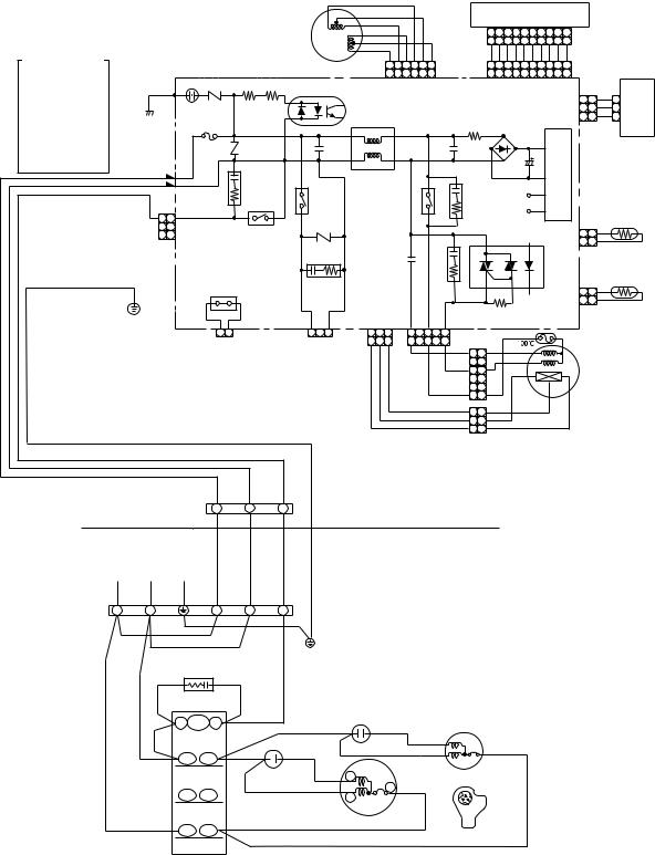
FILE NO. SVM-04031
3-4. RAS-24UFP-ES3 / RAS-24UA-ES3 |
|
|
|
|
|
|
|
|
|
|
|
|
|
|
|
|
|
|
|
|
|
|
|
|
|
||||||||
|
|
|
|
|
|
|
|
|
|
|
|
ORN |
|
|
|
|
|
|
|
|
|
|
|
|
|
|
|
|
|
|
|
|
|
|
|
|
|
|
|
|
|
|
|
|
|
RED |
|
|
|
|
|
|
|
|
INFRARED RA |
YS RECEIVE |
|
|
|
|
|||||||
|
|
|
|
|
|
|
|
|
|
|
|
|
|
|
|
|
|
|
|
AND INDICA TION P AR TS |
|
|
|
|
|||||||||
|
|
|
|
|
|
|
|
LOUVER |
|
|
|
PNK |
|
|
|
|
|
|
|
|
|
|
|
|
|||||||||
|
|
|
|
|
|
|
|
|
|
|
|
|
|
|
|
|
|
|
|
|
|
|
|
|
|
|
|
|
|
|
|
||
|
|
|
|
|
|
|
|
|
|
|
YEL |
|
|
|
|
|
|
|
|
1 |
2 |
3 4 |
5 |
6 7 |
8 |
9 10 |
|
|
|
|
|||
|
|
|
|
|
|
|
|
MOT OR |
|
|
|
|
|
|
|
|
|
CN25 |
|
|
|
|
|||||||||||
|
|
|
|
|
|
|
|
|
|
|
|
BR W |
|
|
|
|
|
1 2 3 4 5 6 7 8 9 10 |
|
|
|
|
|||||||||||
|
|
|
|
|
|
|
|
|
|
|
|
|
|
|
|
|
|
|
|
|
|
|
|||||||||||
|
|
|
|
|
|
|
|
|
|
|
|
BLU |
|
|
|
|
|
|
|
|
BLU |
BLU |
BLU BLU BLU BLU |
BLU |
BLU BLU WHI |
|
|
|
|
||||
COLOR IDENTIFICA |
TION |
|
|
|
|
|
|
|
|
|
|
|
|
|
|
|
|
|
|
|
|
|
|||||||||||
|
|
|
|
|
|
|
|
|
6 5 |
4 3 2 |
1 |
|
|
1 2 |
3 4 5 |
6 7 8 |
9 10 |
|
|
|
|
||||||||||||
BR W |
: |
BROWN |
|
|
|
|
|
|
|
CN07 |
CN13 |
|
|
|
|
||||||||||||||||||
|
|
|
|
|
|
|
6 |
5 |
4 |
3 |
2 |
1 |
1 |
2 |
3 |
4 |
5 |
6 |
7 |
8 |
9 10 |
|
|
|
|
||||||||
RED |
: |
RED |
|
|
|
|
|
|
|
|
|
|
|
|
|
|
|||||||||||||||||
|
|
SG01 |
|
R09 |
R507 |
|
|
|
|
|
|
|
|
|
|
|
|
|
|
|
|
|
|
|
|
|
|
|
|
|
|||
WHI |
: |
WHITE |
BLK |
|
IC04 |
|
|
|
|
|
|
|
|
|
|
|
|
|
|
|
|
|
|
|
CN100 |
CN101 |
SWITCH |
||||||
YEL |
: |
YELLOW |
|
|
|
|
|
|
|
|
|
|
|
MAIN PCB |
|
|
|
|
|
|
|
|
|
||||||||||
BLU |
: |
BLUE |
P04 |
R22 |
|
|
|
|
|
|
|
|
|
|
|
|
|
|
|
|
|
|
|
1 |
1 |
WHI |
1 |
PCB |
|||||
|
|
|
|
|
|
|
|
|
|
MCC-865A |
|
|
|
|
|
|
|
|
|
GR Y |
|||||||||||||
BLK |
: |
BLACK |
|
|
|
|
|
|
|
|
|
|
|
|
|
|
|
|
|
|
|
|
|
2 |
2 |
2 |
|
||||||
|
|
|
|
|
|
|
|
|
|
|
|
|
|
|
|
|
|
|
|
|
|
|
|
|
3 |
3 GR Y 3 |
|
||||||
GR Y |
: |
GRA Y |
|
F01 |
FUSE |
|
|
|
|
L01 |
|
|
|
|
|
|
|
|
|
|
|
|
|
|
|
|
|
||||||
|
|
|
|
|
|
|
|
|
|
|
|
|
|
|
|
|
|
|
|
|
|
|
|
|
|
||||||||
PNK |
: |
PINK |
|
T6.3A |
250V AC |
|
|
|
|
|
|
|
|
|
|
|
R01 |
|
|
|
|
|
|
|
|
|
|
|
|
|
|||
|
|
|
|
|
|
|
|
|
|
|
|
|
|
|
DB01 |
|
|
|
|
|
|
|
MCC-865B |
||||||||||
ORN |
: |
ORANGE |
|
|
|
|
|
|
|
|
|
|
|
|
|
|
|
|
|
|
|
|
|
|
|
|
|
||||||
|
|
|
|
|
|
|
|
|
|
|
|
|
|
|
|
|
|
|
|
|
|
|
|
|
|
|
|
|
|
||||
GRN&YEL |
: |
GREEN& |
|
|
|
R21 |
|
C15 |
|
|
|
|
|
|
|
|
|
C01 |
|
|
|
|
|
|
|
|
Y |
|
|
|
|
||
|
|
YELLOW |
|
|
|
|
|
|
|
|
|
|
|
|
|
|
|
|
|
|
|
|
|
|
|
|
|
||||||
|
|
|
|
|
|
|
|
|
|
|
|
|
|
|
|
|
|
|
|
|
|
|
|
|
|
|
|
|
|
|
|
||
GRN |
: |
GREEN |
|
|
|
|
|
|
|
|
|
|
|
|
|
|
|
|
|
|
|
|
C02 |
|
|
|
POWER SUPPL CIRCUIT |
|
|
|
|
||
PUR |
: |
PURPLE |
CN30 |
|
|
|
|
|
|
|
|
|
|
|
|
|
|
|
|
|
|
|
|
|
|
|
|
|
|
||||
|
|
|
BLK |
|
|
|
|
|
|
|
|
|
|
|
|
|
|
|
|
|
|
|
|
|
|
|
|
|
|
|
|||
|
|
|
|
|
|
|
|
|
|
|
|
|
|
|
|
|
|
|
|
|
|
|
|
|
|
|
|
|
|
|
|||
|
|
|
WHI |
CN31 |
|
|
CR02 |
|
R Y401 |
|
|
|
|
|
|
|
|
R Y501 |
|
|
|
|
|
|
|
|
|
|
|
|
|||
|
|
|
RED |
|
|
|
|
|
|
|
|
|
|
|
|
|
|
CR502 |
|
DC12V |
|
|
|
|
|
|
|
||||||
|
|
|
|
|
|
|
|
|
|
|
|
|
|
|
|
|
|
|
|
|
|
|
|
|
|
|
|
|
|||||
|
|
|
|
|
|
|
|
|
|
|
|
|
|
|
|
|
|
|
|
|
|
|
|
|
|
|
|
|
|
||||
|
|
|
|
|
|
|
R Y04 |
|
|
|
|
|
|
|
|
|
|
|
|
|
|
|
|
|
|
|
|
THERMO |
|||||
|
|
|
|
CN27 |
|
|
|
|
|
|
|
|
|
|
|
|
|
|
|
DC5V |
|
|
|
|
|
|
|||||||
|
|
|
|
|
|
|
|
|
|
|
|
|
|
|
|
|
|
|
|
|
|
|
|
|
|
|
SENSOR |
||||||
|
|
|
|
1 |
1 |
|
|
|
|
|
|
|
|
|
|
|
|
|
|
|
|
|
|
|
|
|
|
|
|||||
|
|
|
|
|
|
|
|
|
|
|
|
|
|
|
|
|
|
|
|
|
|
|
|
|
|
|
|
|
|||||
|
|
|
|
|
|
|
|
|
|
|
|
|
|
|
|
|
|
|
|
|
|
|
|
|
|
|
CN03 |
(TA) |
|
||||
|
|
|
|
|
|
|
|
|
R405 |
|
|
|
|
|
|
|
|
|
|
|
|
|
|
|
|
|
|
|
|
||||
|
|
|
|
|
|
|
|
|
|
|
|
|
|
|
|
|
|
|
|
|
|
|
|
|
|
|
|
1 |
1 |
BLK |
|
|
|
|
|
|
|
3 3 |
|
|
|
|
|
|
|
|
|
|
|
|
|
|
|
|
|
|
|
|
|
|
|
|
|
||||
|
|
|
|
|
|
|
|
|
|
|
|
|
|
|
|
|
|
|
CR501 |
|
|
IC03 |
|
|
|
|
2 |
2 |
BLK |
|
|
||
|
|
|
|
|
|
|
|
|
CR401 |
|
|
|
|
C501 |
|
|
|
|
|
|
|
|
|
|
|
|
|
|
|
HEA T |
|||
|
|
|
|
|
|
|
|
|
|
|
|
|
|
|
|
|
|
|
|
|
|
|
|
|
|
|
|
|
|
||||
|
|
|
|
|
|
|
|
|
|
|
|
|
|
|
|
|
|
|
|
|
|
|
|
|
|
|
|
|
|
EXCHANGER |
|||
|
|
|
|
|
|
|
|
|
|
|
|
|
|
|
|
|
|
|
|
|
|
|
|
|
|
|
|
|
|
|
|||
|
|
|
|
|
|
|
|
|
|
|
|
|
|
|
|
|
|
|
|
|
|
|
|
|
|
|
|
|
|
|
SENSOR |
||
|
|
|
GRN&YEL |
|
|
|
|
|
|
|
|
|
|
|
|
|
|
|
|
|
|
|
|
|
|
|
|
CN01 |
(TC) |
|
|||
|
|
|
|
|
|
J401 |
|
|
|
|
|
|
|
|
|
|
|
|
|
|
|
|
|
|
|
|
|
|
1 |
1 |
BLK |
|
|
|
|
|
|
|
|
|
|
|
|
|
|
|
|
|
|
|
|
|
|
|
|
|
|
|
|
|
|
|
2 |
2 |
BLK |
|
|
|
|
|
|
|
|
|
|
|
|
|
|
|
|
|
|
|
|
|
|
|
R506 |
|
|
|
|
|
|
|
|
|
|
||
|
|
|
|
|
|
2 1 |
CN402 |
CN401 |
1 2 3 |
CN1 1 |
1 2 |
3 |
|
|
5 |
|
3 |
1 CN10 |
|
|
|
BLK |
|
|
|
|
|
|
|
|
|
||
|
|
|
|
|
FOR FLOA |
T SWITCH |
FOR DRAIN PUMP |
|
1 |
2 |
3 |
|
|
5 |
|
3 |
1 |
|
|
|
|
|
|
|
|
|
|
|
|
|
|
||
|
|
|
|
|
|
|
|
|
|
|
|
|
|
WHI |
1 |
1 |
|
WHI |
|
|
|
|
|
|
|
|
|
||||||
|
|
|
|
|
|
(OPTION) |
|
(OPTION) |
|
|
|
|
|
|
|
|
|
|
|
|
|
|
|
|
|
|
|
||||||
|
|
|
|
|
|
|
|
|
|
|
|
|
|
|
|
|
|
|
RED |
|
|
|
RED |
|
|
|
|
|
FA N |
|
|
||
|
|
|
|
|
When you use float |
|
|
|
|
|
|
|
|
|
|
|
3 |
3 |
|
|
PUR |
|
|
|
|
MOT OR |
|
|
|||||
|
|
|
|
|
|
|
|
|
|
|
|
|
|
|
|
|
|
|
|
|
|
|
|
|
|||||||||
|
|
|
|
|
switch you should |
|
|
|
|
|
|
|
|
|
|
|
|
|
|
|
|
|
|
|
|
|
|
|
|
|
|
||
|
|
|
|
|
|
cut J401 |
|
|
|
|
|
|
|
|
|
|
|
BLK |
6 |
6 |
|
|
|
|
|
|
|
|
|
|
|
|
|
|
|
|
|
|
|
|
|
|
|
|
|
|
|
|
|
|
|
|
|
|
|
|
|
|
|
|
|
|
|
|
|
||
|
|
|
|
|
|
|
|
|
|
|
|
|
|
|
|
BR W |
|
|
3 |
3 |
|
|
|
BLU |
|
|
|
|
|
|
|
||
|
|
|
|
|
|
|
|
|
|
|
|
|
|
|
|
GR Y |
|
|
|
|
|
|
|
|
|
|
|
|
|
|
|||
|
|
|
|
|
|
|
|
|
|
|
|
|
|
|
|
|
|
2 |
2 |
|
|
|
|
|
|
|
|
|
|
|
|
||
|
|
|
|
|
|
|
|
|
|
|
|
|
|
|
|
YEL |
|
|
|
|
GR Y |
|
|
|
|
|
|
|
|||||
|
|
|
|
|
|
|
|
|
|
|
|
|
|
|
|
|
|
1 |
1 |
|
|
|
|
|
|
|
|
|
|||||
|
|
|
|
|
|
|
|
|
|
|
|
|
|
|
|
|
|
|
|
|
|
|
|
|
|
|
|
|
|
|
|
||
|
|
|
|
INDOOR |
|
|
|
|
|
|
|
|
|
INDOOR |
|
|
|
|
|
|
|
|
|
|
|
|
|
|
|||||
|
|
|
|
TERMINAL |
1 |
2 |
3 |
|
|
|
|
|
|
|
|
|
|
|
|
|
|
|
|
|
|
|
|
||||||
|
|
|
|
BLOCK |
|
|
|
|
|
|
|
|
|
UNIT |
|
|
|
|
|
|
|
|
|
|
|
|
|
|
|
||||
|
|
|
POWER SUPPLY |
|
|
|
|
|
|
|
|
|
|
OUTDOOR |
|
|
|
|
|
|
|
|
|
|
|
|
|
|
|||||
|
|
|
220 − 240 V ~ 50 Hz |
|
|
|
|
|
|
|
|
|
|
|
|
|
|
|
|
|
|
|
|
|
|
|
|||||||
|
|
|
|
|
|
|
|
|
|
|
|
UNIT |
|
|
|
|
|
|
|
|
|
|
|
|
|
|
|
||||||
|
|
|
|
|
|
|
|
|
|
|
|
|
|
|
|
|
|
|
|
|
|
|
|
|
|
|
|
|
|
||||
OUTDOOR |
L |
N |
|
1 |
2 |
3 |
|
|
|
|
|
|
|
|
|
|
|
|
|
|
|
|
|
|
|
|
|
|
|
|
|
||
TERMINAL |
|
|
|
|
|
|
|
|
|
|
|
|
|
|
|
|
|
|
|
|
|
|
|
|
|
|
|||||||
BLOCK |
|
BLK |
|
|
|
GRN&YEL |
|
|
|
|
|
|
|
|
|
|
|
|
|
|
|
|
|
|
|
|
|
|
|
|
|
||
|
|
|
|
|
|
|
|
|
|
|
|
|
|
|
|
|
|
|
|
|
|
|
|
|
|
|
|
|
|
|
|
|
|
|
|
|
BLK |
RED |
|
|
|
|
|
|
|
|
|
|
|
|
|
|
|
|
|
|
|
|
|
|
|
|
|
|
|
|
|
|
|
|
|
|
|
|
CHASSIS |
|
|
|
|
|
|
|
|
|
|
|
|
|
|
|
|
|
|
|
|
|
|
|
|
||
|
|
|
|
RED |
|
|
|
|
|
|
|
|
|
|
|
|
|
|
|
|
|
|
|
|
|
|
|
|
|
|
|
||
|
|
|
|
|
|
|
|
|
|
|
|
|
|
|
|
|
|
|
|
|
|
|
|
|
|
|
|
|
|
|
|
|
|
|
|
|
|
|
BLK |
BLK |
GRY |
|
|
|
|
|
|
|
|
|
|
|
|
|
|
|
|
|
|
|
|
|
|
|
|
|
|
|
|
|
|
|
SPARK KILLER |
|
|
|
|
|
|
|
|
|
|
|
|
|
|
|
|
|
|
|
|
|
|
|
|
|
|
|
|
|
|
|
|
|
A1 52C A2 |
|
|
RED |
|
|
|
|
|
|
|
|
|
|
|
|
|
|
|
|
|
|
|
|
|
|
|
|
|
|
|
|
|
|
|
|
|
|
|
|
|
|
|
|
|
|
|
|
|
|
|
|
|
|
|
|
|
|
|
|
|
|
|
|
|
|
|
RED |
|
|
|
|
CAPACITOR |
|
|
WHI |
|
|
BLK |
|
|
|
|
|
|
|
|
|
|
||||||||
|
|
|
|
|
R |
U |
RED |
|
|
|
|
RED |
|
|
|
|
|
|
|
|
|
|
|
|
|||||||||
|
|
|
|
|
|
|
|
|
|
|
|
|
|
|
|
|
|
|
|
|
|
|
|
|
|
|
|
|
|
|
|
||
|
|
|
|
|
|
|
CAPACITOR |
WHI |
S |
|
|
C |
|
|
|
|
|
FAN MOTOR |
|
|
|
|
|
|
|
|
|
|
|
|
|||
|
|
|
|
|
S |
V |
|
|
PNK |
R |
|
|
|
BLK |
|
|
C |
|
|
|
|
|
|
|
|
|
|
|
|
|
|
||
|
|
|
|
|
|
|
|
|
|
|
|
|
|
|
|
R |
S |
|
|
|
|
|
|
|
|
|
|
|
|
|
|||
|
|
|
|
|
|
|
|
|
COMPRESSOR |
|
|
|
|
|
|
|
|
|
|
|
|
|
|
|
|
|
|
||||||
T W
COMPRESSOR TERMINAL
MAGNETIC CONTACTOR
− 12 −

FILE NO. SVM-04031
4. SPECIFICATION OF ELECTRICAL PARTS
4-1. Indoor Unit
No. |
Parts name |
Type |
|
|
Specifications |
|
|
|
|
|
|
||
1 |
Fan motor (for indoor) |
AFP-220-50-4A |
|
Output (Rated) 50W, 220-240V |
||
|
|
|
|
|
|
|
2 |
Thermo sensor (TA-sensor) |
——— |
10k |
Ω at 25°C |
||
|
|
|
|
|
||
3 |
DC-DC transformer (T01) |
SWT-47 |
|
DC 390V, Secondary DC 12V, 7V |
||
|
|
|
|
|
|
|
4 |
Microcomputer |
TMP87CM40AN |
|
|
|
|
|
|
|
|
|
|
|
5 |
Heat exchanger sensor |
——— |
10k |
Ω at 25°C |
||
(TC-sensor) |
||||||
|
|
|
|
|
||
|
|
|
|
|
||
6 |
Line filter (L01) |
SS11V-R07190 |
|
19mH, AC0.7A |
||
|
|
|
|
|
||
7 |
Diode (DB01) |
D3SBA60 |
|
4A, 600V |
||
|
|
|
|
|
||
8 |
Capacitor (C02) |
KMH400VSSN47M22S 47µF, 400V |
||||
|
|
|
|
|
||
9 |
Fuse (F01) |
TSCR |
|
T6.3A, 250V |
||
|
|
|
|
|
||
10 |
Varistor (R21, R22) |
15G561K |
|
560V |
||
|
|
|
|
|
||
11 |
Resistor (R01) |
RF-2TK5R6 |
|
5.6Ω , 2W |
||
|
|
|
|
|
||
12 |
Louver motor |
MP35EA12 |
|
Output (Rated) 2W, 6poles, 4phase, |
||
|
DC 12V |
|||||
|
|
|
|
|||
|
|
|
|
|
|
|
4-2. Outdoor Unit (RAS-18UAH-ES3)
No. |
Parts name |
Type |
Specifications |
|
||||
|
|
|
|
|
|
|
||
|
|
|
Output (Rated) 1500W, 2poles, 1phase, 220 – 240V, 50Hz |
|||||
|
|
|
|
|
|
|
|
|
1 |
Compressor |
PA225X3F-4L |
Winding resistance (Ω |
) |
|
|
Red-Black |
White-Black |
|
|
|
|
|
|
|
|
|
|
|
|
(at 20°C) |
|
|
|
1.35 |
2.68 |
|
|
|
|
|
|
|
||
|
|
|
Output (Rated) 65W, 6poles, 1phase, 220 – 240V, 50Hz |
|||||
|
|
|
|
|
|
|||
2 |
Fan motor (for outdoor) |
HF-240-42B-2 |
Winding resistance (Ω) |
|
Red-Black |
White-Black |
||
|
|
|
|
|
|
|
|
|
|
|
|
(at 20°C) |
|
|
|
176.2 |
290.5 |
|
|
|
|
|
|
|
|
|
3 |
Running capacitor |
451205KQ |
AC 450V, 2µF |
|
|
|
|
|
(for fan motor) |
|
|
|
|
|
|||
|
|
|
|
|
|
|
|
|
|
|
|
|
|
|
|
|
|
4 |
Running capacitor |
371456JCR |
AC 370V, 45µF |
|
|
|
|
|
(for compressor) |
|
|
|
|
|
|||
|
|
|
|
|
|
|
|
|
|
|
|
|
|
|
|
|
|
5 |
Solenoid coil |
VHV (STF) |
AC 220 – 240V |
|
|
|
|
|
(for 4-way valve) |
|
|
|
|
|
|||
|
|
|
|
|
|
|
|
|
|
|
|
|
|
|
|
|
|
6 |
Thermo sensor |
TE / TD |
10kΩ at 25°C / 50kΩ |
at 25°C |
|
|
||
|
|
|
|
|
|
|
|
|
7 |
Magnetic contactor |
CLK-26J |
220 – 240V, 50Hz |
|
|
|
|
|
|
|
|
|
|
|
|
|
|
8 |
Transformer |
TT-05 |
220 – 240V |
|
|
|
|
|
|
|
|
|
|
|
|
|
|
9 |
Microcomputer |
TMP47C840N |
|
|
|
|
|
|
|
|
|
|
|
|
|
|
|
10 |
Varistor (R73, 74) |
15G471K |
470V |
|
|
|
|
|
11 |
Fuse (F01) |
TSCR |
T6.3A, 250V |
|
|
|
|
|
– 13 –
FILE NO. SVM-04031-(1)
4-3. Outdoor Unit (RAS-18UA-ES3)
No. |
Parts name |
Type |
Specifications |
|
||
|
|
|
|
|
|
|
|
|
|
Output (Rated) 1500W, 2poles, 1phase, 220 – 240V, 50Hz |
|||
|
|
|
|
|
|
|
1 |
Compressor |
5KS225DAA |
Winding resistance (Ω) |
Red-Black |
White-Black |
|
|
|
|
|
|
|
|
|
|
|
(at 20°C) |
1.632 |
2.457 |
|
|
|
|
|
|
|
|
|
|
|
Output (Rated) 42W, 6poles, 1phase, 220 – 240V, 50Hz |
|||
|
|
|
|
|
|
|
2 |
Fan motor (for outdoor) |
HF-240-42B-1 |
Winding resistance (Ω) |
Red-Black |
White-Black |
|
|
|
|
|
|
|
|
|
|
|
(at 20°C) |
176.2 |
290.5 |
|
|
|
|
|
|
|
|
3 |
Running capacitor |
451205KQ |
AC 450V, 2µF |
|
|
|
(for fan motor) |
|
|
||||
|
|
|
|
|
|
|
|
|
|
|
|
|
|
4 |
Running capacitor |
371456JCR |
AC 370V, 45µF |
|
|
|
(for compressor) |
|
|
||||
|
|
|
|
|
|
|
|
|
|
|
|
|
|
5 |
Magnetic contactor |
CLK-26J |
220 – 240V, 50Hz |
|
|
|
|
|
|
|
|
|
|
4-4. Outdoor Unit (RAS-24UAH-ES3)
No. |
Parts name |
Type |
Specifications |
|
|||
|
|
|
|
|
|
||
|
|
|
Output (Rated) 2200W, 2poles, 1 phase, 220 – 240V, 50Hz |
||||
|
|
|
|
|
|
|
|
1 |
Compressor |
PA290X3F-4MS |
Winding resistance (Ω |
) |
|
Red-Black |
White-Black |
|
|
|
|
|
|
|
|
|
|
|
(at 20°C) |
|
|
1.07 |
2.20 |
|
|
|
|
|
|
||
|
|
|
Output (Rated) 65W, 6poles, 1phase, 220 – 240V, 50Hz |
||||
|
|
|
|
|
|
|
|
2 |
Fan motor (for outdoor) |
KPG6-71SB5P-T1 |
Winding resistance (Ω |
) |
|
Red-Black |
White-Black |
|
|
|
|
|
|
|
|
|
|
|
(at 20°C) |
|
|
64.4 |
127.4 |
|
|
|
|
|
|
|
|
3 |
Running capacitor |
451355KQ |
AC 450V, 3.5µF |
|
|
|
|
(for fan motor) |
|
|
|
|
|||
|
|
|
|
|
|
|
|
|
|
|
|
|
|
|
|
4 |
Running capacitor |
371456JCR |
AC 370V, 45µF |
|
|
|
|
(for compressor) |
|
|
|
|
|||
|
|
|
|
|
|
|
|
|
|
|
|
|
|
|
|
5 |
Solenoid coil |
VHV (STF) |
AC 220 – 240V |
|
|
|
|
|
(for 4-way valve) |
|
|
|
|
||
|
|
|
|
|
|
|
|
|
|
|
|
|
|
|
|
6 |
Thermo sensor |
TE / TD |
10kΩ at 25°C / 50kΩ |
at 25°C |
|
|
|
|
|
|
|
|
|
|
|
7 |
Magnetic contactor |
CLK-35J |
220 – 240V, 50Hz |
|
|
|
|
|
|
|
|
|
|
|
|
8 |
Transformer |
TT-05 |
220 – 240V |
|
|
|
|
|
|
|
|
|
|
|
|
9 |
Microcomputer |
TMP47C840N |
|
|
|
|
|
|
|
|
|
|
|
|
|
10 |
Varistor (R73, 74, 86) |
15G471K |
470V |
|
|
|
|
|
|
|
|
|
|
|
|
11 |
Fuse (F01) |
TSCRT |
6.3A, 250V |
|
|
|
|
|
|
|
|
|
|
|
|
– 14 –
FILE NO. SVM-04031-(1)
4-5. Outdoor Unit (RAS-24UA-ES3)
No. |
Parts name |
Type |
Specifications |
|
|
|
|
|
Output (Rated) 2200W, 2poles, 1 phase, 220 − 240V, 50Hz |
||
1 |
Compressor |
5JS315DAB |
Winding resistance (Ω) |
Red-Black |
White-Black |
|
|
|
(at 20°C) |
0.83 |
2.257 |
|
|
|
|
|
|
|
|
|
Output (Rated) 65W, 6poles, 1 phase, 220 − |
240V, 50Hz |
|
2 |
Fan motor (for outdoor) |
KFG6-71SB5P-T |
Winding resistance (Ω) |
Red-Black |
White-Black |
|
|
|
|
|
|
|
|
|
(at 20° C) |
64.4 |
127.4 |
|
|
|
|
|
|
3 |
Running capacitor |
451355KQ |
AC 450V, 3.5μF |
|
|
|
(for fan motor) |
|
|
|
|
4 |
Running capacitor |
371456JCR |
AC 370V, 45μF |
|
|
(for compressor) |
|
|
|
|
|
|
|
|
|
|
|
5 |
Magnetic contactor |
CLK-35J |
220 − 240V, 50Hz |
|
|
|
|
|
|
|
|
– 15 –
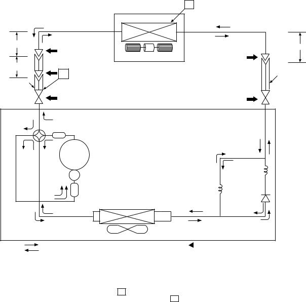
FILE NO. SVM-04031
5. REFRIGERATION CYCLE DIAGRAM
5-1. RAS-18UFHP-ES3 / RAS-18UAH-ES3
|
|
|
Indoor unit |
T |
|
|
|
|
|
|
|
Cooling |
Evaporator |
|
|
|
|
|
|
0.39m |
Heating |
|
0.49m |
|
(Connecting pipe) |
|
|||
|
(Connecting pipe) |
|||
|
|
|||
|
12.70 mm |
|
|
|
|
Multi blade fan |
6.35 mm |
||
|
|
|
||
0.39m |
|
|
||
|
|
|
||
(Flexible pipe) |
|
|
|
|
|
12.70 mm |
P |
|
O.D.:6.35 mm |
|
O.D.:12.70 mm |
|
|
|
|
Packed valve |
|
|
Packed valve |
|
( 12.70) |
|
|
( 6.35) |
|
Heating |
|
|
|
Cooling |
4-way valve |
|
|
|
|
Muffler |
|
|
|
Heating |
Cooling Compressor |
PA225X3F-4L |
|
|
|
|
|
|
Capillary tube |
|
|
|
|
1.0x1500S |
|
|
|
Capillary tube |
|
|
Accumulator |
|
1.7x700S |
|
|
|
Condenser |
|
|
|
|
|
|
Refrigerant |
|
|
Propeller fan |
|
R-410A 1.30 Kg |
Cooling |
Outdoor unit |
Mark ( |
|
) means check points of Gas Leak |
|
||||
|
||||
Heating |
|
|
|
|
|
|
Standard |
Surface temp. of heat |
|
Ambient temp. |
|
|
|
Fan speed |
conditions DB/WB |
|||
|
50Hz |
pressure P |
exchanger interchanging |
|||
|
(indoor) |
(°C) |
||||
|
|
(MPaG) |
pipe T (°C) |
|||
|
|
|
Indoor |
Outdoor |
||
|
|
|
|
|||
|
|
|
|
|
||
|
|
|
|
|
|
|
|
Standard |
2.7 |
45.0 |
High |
20/– |
7/6 |
|
|
|
|
|
|
|
Heating |
High temperature*1 |
3.0 ~ 3.8 |
49.0 ~ 58.0 |
Low |
27/– |
24/18 |
|
|
|
|
|
|
|
|
Low temperature |
2.0 |
34.0 |
High |
20/– |
–10/–10 |
|
|
|
|
|
|
|
|
Standard |
0.9 |
10.0 |
High |
27/19 |
35/24 |
|
|
|
|
|
|
|
Cooling |
High temperature |
1.0 |
15.0 |
High |
32/23 |
43/26 |
|
|
|
|
|
|
|
|
Low temperature |
0.6 |
1.0 |
Low |
21/15 |
21/15 |
|
|
|
|
|
|
|
Note : Measure the heat exchanger temperature at the center of U-bend. (By means of TC sensor.) *1 : During heating overload, the high temperature limit control operation is included.
– 16 –

FILE NO. SVM-04031
5-2. RAS-18UFP-ES3 / RAS-18UA-ES3
0.39m |
|
|
|
|
|
|
|
||||||
|
|
|
|||||||||||
(Connecting pipe) |
|
|
|
||||||||||
12.70 mm |
|
|
|
|
|
|
|
|
|
||||
|
|
|
|
|
|
|
|||||||
|
|
|
|
||||||||||
|
|
|
|
|
|
|
|
|
|
|
|
|
|
0.39m |
|
|
|
|
|
|
|
||||||
|
|
|
|
|
|
||||||||
|
|
|
|
||||||||||
(Flexible pipe) |
|
|
|
|
|
|
|
|
|
||||
12.70 mm |
|
|
|
|
|
|
|
P |
|
|
|||
|
|
|
|
||||||||||
|
|
|
|
|
|
|
|||||||
|
|
|
|
|
|
|
|
|
|
|
|
|
|
O.D.:12.70 mm |
|
|
|
|
|
|
|
|
|
||||
|
|
|
|
|
|||||||||
|
|
|
|
||||||||||
|
|
|
|
|
|
|
Packed valve |
||||||
|
|
|
|
|
|
|
|||||||
|
|
|
|
|
|
|
|
|
( |
12.70) |
|||
|
|
|
|
|
|
|
|
||||||
|
|
|
|
|
|
|
|
||||||
T
Indoor unit
Evaporator
0.49m (Connecting pipe)6.35 mm
Multi blade fan
O.D.:6.35 mm
Packed valve ( 6.35)
Compressor |
5KS225DAA |
|
Capillary tube |
|
|
|
1.7x600S |
|
|
Condenser |
|
|
|
|
Refrigerant |
|
|
Propeller fan |
R-410A 1.14 Kg |
|
|
|
Outdoor unit Mark ( ) means check points of Gas Leak
|
|
Standard |
Surface temp. of heat |
|
Ambient temp. |
|
|
|
Fan speed |
conditions DB/WB |
|||
|
50Hz |
pressure P |
exchanger interchanging |
|||
|
(indoor) |
(°C) |
||||
|
|
(MPaG) |
pipe T (°C) |
|||
|
|
|
Indoor |
Outdoor |
||
|
|
|
|
|
||
|
|
|
|
|
|
|
|
Standard |
0.9 |
10.0 |
High |
27/19 |
35/24 |
|
|
|
|
|
|
|
Cooling |
High temperature |
1.0 |
13.0 |
High |
32/23 |
43/26 |
|
|
|
|
|
|
|
|
Low temperature |
0.6 |
2.0 |
Low |
21/15 |
21/15 |
|
|
|
|
|
|
|
Note : Measure the heat exchanger temperature at the center of U-bend. (By means of TC sensor.)
– 17 –
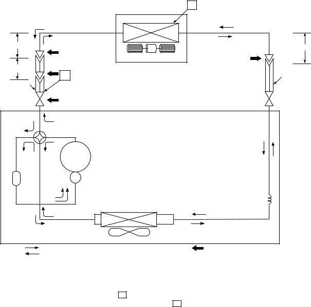
FILE NO. SVM-04031
5-3. RAS-24UFHP-ES3 / RAS-24UAH-ES3
|
Cooling |
0.39m |
Heating |
(Connecting pipe) |
|
12.70 mm |
|
0.39m |
|
(Flexible pipe) |
|
12.70 mm |
P |
O.D.:12.70 mm |
|
|
Packed valve |
|
( 12.70) |
T
Indoor unit
Evaporator |
Multi blade fan |
Packed valve
( 6.35) 
0.49m (Connecting pipe)6.35 mm
O.D.:6.35 mm
|
Heating |
|
|
|
Cooling |
4-way valve |
|
|
|
Heating |
Cooling Compressor |
PA290X3F-4MS |
|
|
Tank |
|
|
|
|
|
|
|
|
Capillary tube |
|
|
Condenser |
|
2.0x700S |
|
|
|
|
|
|
|
|
|
Refrigerant |
|
|
Propeller fan |
|
R-410A 1.60 Kg |
|
Cooling |
Outdoor unit |
Mark ( |
) means check points of Gas Leak |
|
Heating |
|
|
|
|
|
Standard |
Surface temp. of heat |
|
|
Ambient temp. |
||
|
|
Fan speed |
conditions DB/WB |
|||||
|
50Hz |
pressure P |
exchanger interchanging |
|||||
|
(indoor) |
|
(°C) |
|||||
|
|
(MPaG) |
pipe T (°C) |
|
||||
|
|
|
|
Indoor |
|
Outdoor |
||
|
|
|
|
|
|
|
||
|
|
|
|
|
|
|
|
|
|
Standard |
2.7 |
43.0 |
High |
20/– |
|
7/6 |
|
|
|
|
|
|
|
|
|
|
Heating |
High temperature*1 |
3.1 ~ 4.0 |
52.0 ~ 59.0 |
Low |
27/– |
|
24/18 |
|
|
|
|
|
|
|
|
|
|
|
Low temperature |
2.7 |
36.0 |
High |
20/– |
|
–10/–10 |
|
|
|
|
|
|
|
|
|
|
|
Standard |
0.9 |
11.0 |
High |
27/19 |
|
35/24 |
|
|
|
|
|
|
|
|
|
|
Cooling |
High temperature |
0.8 |
12.0 |
High |
32/23 |
|
43/26 |
|
|
|
|
|
|
|
|
|
|
|
Low temperature |
0.5 |
1.0 |
Low |
21/15 |
|
21/15 |
|
|
|
|
|
|
|
|
|
|
Note : Measure the heat exchanger temperature at the center of U-bend. (By means of TC sensor.) *1 : During heating overload, the high temperature limit control operation is included.
– 18 –
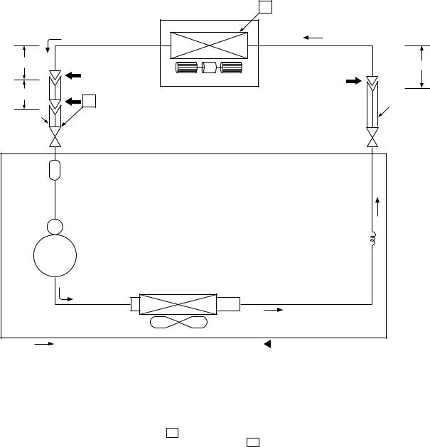
FILE NO. SVM-04031
5-4. RAS-24UFP-ES3 / RAS-24UA-ES3
|
Cooling |
0.39m |
|
(Connecting pipe) |
|
12.70 mm |
|
0.39m |
|
(Flexible pipe) |
P |
12.70 mm |
O.D.:12.70 mm
Packed valve
 ( 12.70 )
T
Indoor unit |
Evaporator |
Multi blade fan |
Packed valve ( 6.35) 
0.49m (Connecting pipe)6.35 mm
O.D.:6.35 mm
Tank |
|
|
|
|
|
Capillary tube |
|
|
|
|
2.0x700S |
Compressor |
5JS315DAG01 |
|
|
|
Condenser |
|
|
|
|
Refrigerant |
|
|
Propeller fan |
R-410A |
1.60 Kg |
Cooling |
Outdoor unit |
Mark ( |
|
) means check points of Gas Leak |
|
||||
|
|
|
Standard |
Surface temp. of heat |
|
Ambient temp. |
|
|
|
Fan speed |
conditions DB/WB |
|||
|
50Hz |
pressure P |
exchanger interchanging |
|||
|
(indoor) |
(°C) |
||||
|
|
(MPaG) |
pipe T (°C) |
|||
|
|
|
Indoor |
Outdoor |
||
|
|
|
|
|
||
|
|
|
|
|
|
|
|
Standard |
0.9 |
6.0 |
High |
27/19 |
35/24 |
|
|
|
|
|
|
|
Cooling |
High temperature |
0.8 |
10.0 |
High |
32/23 |
43/26 |
|
|
|
|
|
|
|
|
Low temperature |
0.6 |
2.0 |
Low |
21/15 |
21/15 |
|
|
|
|
|
|
|
Note : Measure the heat exchanger temperature at the center of U-bend. (By means of TC sensor.)
– 19 –
FILE NO. SVM-04031
6. CONTROL BLOCK DIAGRAM
6-1. RAS-18UFHP-ES3, RAS-24UFHP-ES3
|
|
|
|
|
|
|
|
Indoor Unit Control Panel |
|
|
|
|
|
|
|||||||||||||
|
|
|
|
|
|
|
|
|
|
|
|
|
|
|
|
|
|
|
M.C.U. |
8 MHz |
|
|
|
|
|||
|
|
|
|
|
|
|
|
|
|
|
|
Functions |
|
|
|
|
|
|
|
|
|
|
|
Hi POWER |
|||
|
|
Heat Exchanger Sensor |
|
|
|
|
|
|
|
|
|
|
|
|
|
|
|
||||||||||
|
|
|
|
|
|
|
|
|
|
|
|
|
|
|
|
|
Display |
||||||||||
|
|
|
|
|
|
|
|
|
|
|
|
• |
Louver Control |
|
|
|
|
|
|||||||||
|
|
|
|
|
|
|
|
|
|
|
|
|
|
|
|
|
|
||||||||||
|
|
|
|
|
|
|
|
|
|
|
|
|
|
||||||||||||||
|
|
|
|
|
|
|
|
|
|
|
|
• |
|
|
|
|
|
|
|
|
|
|
|
|
|
|
FILTER Sign |
|
|
Temperature Sensor |
|
|
|
|
3-minute Delay at Restart for Compressor |
|
|
|
|||||||||||||||||
|
|
|
|
|
|
|
|
|
Display |
||||||||||||||||||
|
|
|
|
|
|
|
|
|
|||||||||||||||||||
|
|
|
|
|
|
|
|
|
|
|
|
• |
Motor Revolution Control |
|
|
|
|
|
|
||||||||
|
|
|
|
|
|
|
|
|
|
|
|
|
|
|
|
|
|
||||||||||
|
|
|
|
|
|
|
|
|
|
|
|
|
PRE DEF. |
||||||||||||||
Infrared Rays Signal Receiver |
|
|
|
|
|
|
|
|
|
|
|
|
|||||||||||||||
|
|
|
|
|
|
|
• |
Processing |
|
|
|
|
|
Sign Display |
|||||||||||||
|
|
|
|
|
|
|
|
|
|
|
|
|
|
|
|
|
|||||||||||
|
|
|
|
|
|
|
|
|
|
|
|
|
|
|
|
|
|
||||||||||
|
|
|
|
|
|
|
|
|
|
|
|
|
|
||||||||||||||
|
|
|
|
|
|
|
|
|
|
|
|
|
(Temperature Processing) |
|
|
|
|
|
TIMER |
||||||||
|
|
|
Initiallizing Circuit |
|
|
|
|
|
|
|
|||||||||||||||||
|
|
|
|
|
|
|
|
|
|
|
|
|
|
|
|
|
|
|
|
|
|
Display |
|||||
|
Infrared |
|
|
|
|
|
|
|
|
|
• |
Timer |
|
|
|
|
|
|
|
|
|
|
|
||||
|
|
|
|
|
|
|
|
|
|
|
|
|
|
|
|
|
|
|
|
|
|
||||||
|
|
|
|
|
|
|
|
|
|
|
|
|
|
|
|
|
|
|
|
|
|
||||||
|
Rays |
Clock Frequence |
|
|
|
|
|
|
|
|
|
|
|
|
|
|
|
OPERATION |
|||||||||
|
|
|
|
|
|
|
|
|
|
|
|
|
|
|
|
|
|
|
|
||||||||
|
|
|
|
|
|
|
|
|
|
|
|
|
|
|
|
|
|
|
|
|
|
||||||
|
|
36.7 kHz |
Oscillator Circuit |
|
|
|
|
• |
Drain Pump ON/OFF |
|
|
|
|
|
Display |
||||||||||||
|
|
|
|
|
|
|
|
|
|
|
|
||||||||||||||||
|
|
|
|
|
|
|
|
|
|
|
|
|
|
|
|
|
|
|
|
|
|
|
|
|
|
|
|
|
|
|
|
|
|
|
|
|
|
|
|
|
|
|
|
|
|
|
|
|
|
|
|
|
|
|
|
|
|
|
|
|
|
|
|
|
|
|
|
• |
Serial Signal Communication |
|
|
|
|
|
Indoor Fan |
||||||||
|
|
|
|
|
|
|
|
|
|
|
|
|
|
|
|
|
|||||||||||
|
|
|
|
|
|
|
|
|
|
|
|
|
|
|
|
||||||||||||
|
|
|
|
|
|
|
|
|
|
|
|
|
|
|
|
|
Motor |
||||||||||
|
|
|
|
|
|
|
|
|
|
|
|
|
|||||||||||||||
|
|
|
|
|
|
|
|
|
|
|
|
|
|
|
|
|
|
|
|
|
|
|
|
|
|
|
|
|
|
|
|
|
|
|
|
|
|
|
|
|
|
|
|
|
|
|
|
|
|
|
|
|
|
||
|
|
|
|
|
|
|
|
|
|
|
|
|
|
|
|
|
|
|
|
|
|
|
|
|
|
||
|
|
|
|
|
|
|
|
|
|
|
|
|
|
|
|
|
|
|
|
|
|
|
|
|
|
|
|
|
|
|
Power Supply |
|
|
|
|
|
|
|
|
|
|
|
|
|
|
|
|
|
|
|
|
|
|||
|
|
|
|
|
|
|
|
|
|
|
|
|
|
|
|
Louver ON/OFF Signal |
|
|
|
|
|||||||
|
Remote |
Circuit |
|
|
|
|
|
|
|
|
|
|
|
|
|
|
|
|
|
|
|
||||||
|
|
|
|
|
|
|
|
|
|
|
|
|
|
|
|
|
|
|
|
|
|
||||||
|
|
|
|
|
|
|
|
|
|
|
|
|
|
|
|
|
|
|
|
|
|
|
|
|
|
||
|
Control |
|
|
|
|
|
|
|
|
|
|
|
|
|
|
|
|
|
|
|
|
|
|
|
|
Louver Motor |
|
|
|
|
|
|
|
|
|
|
|
|
|
|
|
|
|
|
|
|
Louver Driver |
|
|
|
|||||
|
|
|
|
|
|
|
|
|
|
|
|
|
|
|
|
|
|
|
|
|
|
|
|
|
|||
|
|
|
|
|
|
|
|
|
|
|
|
|
|
|
|
|
|
|
|
|
|
|
|
|
|||
|
|
|
|
|
|
|
|
|
|
|
|
|
|
|
|
|
|
|
|
|
|
|
|
|
|
|
|
|
|
|
Noise Filter |
|
|
Serial Signal |
|
|
|
|
|
|
|
|
|
|
|
|
|
|
|||||||
|
|
|
|
|
|
|
|
|
|
|
|
|
|
|
|
|
|
||||||||||
|
|
|
|
|
|
|
|
Transmitter/ |
|
|
Relay |
|
|
|
|
|
|
|
Float |
||||||||
|
|
|
|
|
|
|
|
|
|
|
|
|
|
|
|
|
|
||||||||||
|
|
|
|
|
|
|
|
Receiver |
|
|
RY401 |
|
|
|
|
|
|
|
|
Switch |
|||||||
|
|
|
|
|
|
|
|
|
|
|
|
|
|
|
|
|
|
||||||||||
|
|
|
|
|
|
|
|
|
|
|
|
|
|
|
|
|
|
|
|
|
|
|
|||||
|
|
|
|
|
|
|
|
|
|
|
|
|
|
|
|
|
|
|
|
|
|
|
|
|
|
|
Drain |
From Outdoor Unit |
|
|
|
|
|
|
|
|
|
|
|
|
|
|
|
|
|
|
|
|
|
|
|
|
Pump |
||
|
|
|
|
|
|
|
|
|
|
|
|
|
|
|
|
|
|
|
|
|
|
|
|
|
|||
|
|
|
|
|
|
|
|
|
|
|
|
|
|
|
|
|
|
|
|
|
|
|
|
|
|||
|
|
|
|
|
|
|
|
|
|
|
|
|
|
|
|
|
|
|
|
|
|
|
|
|
|||
|
|
|
|
|
Serial Signal Communication |
|
|
|
|
|
|
|
|
|
|
||||||||||||
|
|
|
|
|
|
|
|
|
|
|
|
|
|
|
|
|
|
|
|
|
|
|
|
|
|
|
|
REMOTE CONTROL
Infrared Rays
Remote Control
Operation (START/STOP)
Operation Mode Selection
AUTO, COOL, DRY, HEAT, FAN ONLY
Temperature Setting
Fan Speed Selection
ON TIMER Setting
OFF TIMER Setting
Louver Auto Swing
Louver Direction Setting
ECO
Hi power
Filter Reset
– 20 –
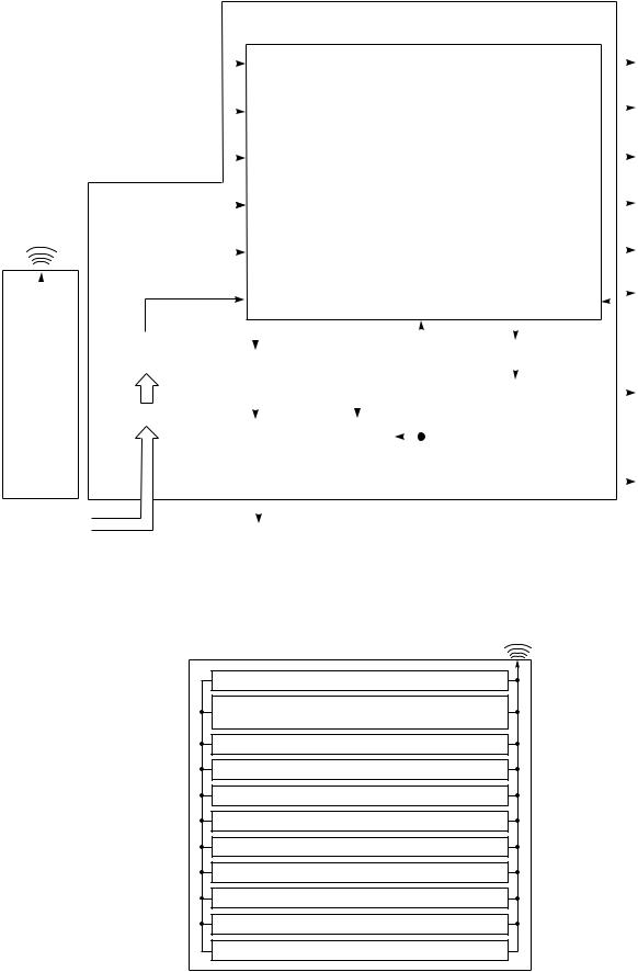
FILE NO. SVM-04031
6-2. RAS-18UFP-ES3, RAS-24UFP-ES3
|
|
|
|
|
|
|
|
Indoor Unit Control Panel |
|
|
|
|
|
|||||||||||
|
|
|
|
|
|
|
|
|
|
|
|
|
|
|
|
|
M.C.U. |
8 MHz |
|
|
|
|||
|
|
|
|
|
|
|
|
|
|
|
|
Functions |
|
|
|
|
Hi POWER |
|||||||
|
|
Heat Exchanger Sensor |
|
|
|
|
|
|
|
|
||||||||||||||
|
|
|
|
|
|
|
|
|
|
Display |
||||||||||||||
|
|
|
|
|
|
|
|
|
|
|
|
• |
Louver Control |
|
|
|
|
|||||||
|
|
|
|
|
|
|
|
|
|
|
|
|
|
|
|
|
||||||||
|
|
|
|
|
|
|
|
|
|
|
|
|
|
|||||||||||
|
|
|
|
|
|
|
|
|
|
|
|
• |
|
|
|
|
|
|
|
|
|
|
|
FILTER Sign |
|
|
Temperature Sensor |
|
|
|
|
3-minute Delay at Restart for Compressor |
|
|
|||||||||||||||
|
|
|
|
|
|
|
|
Display |
||||||||||||||||
|
|
|
|
|
|
|
|
|||||||||||||||||
|
|
|
|
|
|
|
|
|
|
|
|
• |
Motor Revolution Control |
|
|
|
|
|
||||||
|
|
|
|
|
|
|
|
|
|
|
|
|
|
|
|
|
||||||||
|
|
|
|
|
|
|
|
|
|
|
|
|
FAN-ONLY |
|||||||||||
Infrared Rays Signal Receiver |
|
|
|
|
|
|
|
|
|
|
|
|
||||||||||||
|
|
|
|
|
|
|
|
• |
|
|
|
|
|
|
|
|
|
|
|
Sign Display |
||||
|
|
|
|
|
|
|
|
|
|
|
|
|
|
|
|
|
|
|
|
|
|
|
||
|
|
|
|
|
|
|
|
|
|
|
|
Processing |
|
|
|
|
|
|||||||
|
|
|
|
|
|
|
|
|
|
|
|
|
|
|||||||||||
|
|
|
|
|
|
|
|
|
|
|
|
|
(Temperature Processing) |
|
|
|
|
TIMER |
||||||
|
|
|
Initiallizing Circuit |
|
|
|
|
|
|
|
||||||||||||||
|
Infrared |
|
|
|
|
|
|
|
|
|
|
|
|
|
|
|
|
Display |
||||||
|
|
|
|
|
|
|
|
|
|
|
|
|
|
|
|
|
||||||||
|
|
|
|
|
|
|
|
|
|
|
|
|
|
|
|
|
|
|
|
|
|
|||
|
|
|
|
|
|
|
|
|
|
• |
Timer |
|
|
|
|
|
||||||||
|
|
|
|
|
|
|
|
|
|
|
|
|
|
|
||||||||||
|
Rays |
Clock Frequency |
|
|
|
|
|
|
|
|
OPERATION |
|||||||||||||
|
|
|
|
|
|
|
|
|
|
|
|
|
|
|
|
|
||||||||
|
|
|
|
|
|
|
|
|
|
|
|
|
|
|
|
|
|
|
||||||
|
|
36.7 kHz |
Oscillator Circuit |
|
|
|
|
• |
Drain Pump ON/OFF |
|
|
|
|
Display |
||||||||||
|
|
|
|
|
|
|
|
|||||||||||||||||
|
|
|
|
|
|
|
|
|
|
|
||||||||||||||
|
|
|
|
|
|
|
|
|
|
|
|
|
|
|
|
|
|
|
|
|
|
|
|
|
|
|
|
|
|
|
|
|
|
|
|
|
|
|
|
|
|
|
|
|
|
|
|
|
|
|
|
|
|
|
|
|
|
|
|
|
|
• |
Compressor ON/OFF |
|
|
|
|
Indoor Fan |
||||||
|
|
|
|
|
|
|
|
|
|
|
|
|
|
|
|
|||||||||
|
|
|
|
|
|
|
|
|
|
|
|
|
|
|
||||||||||
|
|
|
|
|
|
|
|
|
|
|
|
|
|
|
|
Motor |
||||||||
|
|
|
|
|
|
|
|
|
|
|
|
|
||||||||||||
|
|
|
|
|
|
|
|
|
|
|
|
|
|
|
|
|
|
|
|
|
|
|
|
|
|
|
|
|
|
|
|
|
|
|
|
|
|
|
|
|
|
|
|
|
|
|
|
||
|
|
|
|
|
|
|
|
|
|
|
|
|
|
|
|
|
|
|
|
|
|
|
||
|
|
|
|
|
|
|
|
|
|
|
|
|
|
|
|
|
|
|
|
|
|
|
|
|
|
|
|
Power Supply |
|
|
|
|
|
|
|
|
|
|
|
|
|
|
|
|
|
|
|||
|
|
|
Circuit |
|
|
|
Driver |
|
|
|
|
|
|
|
Louver ON/OFF Signal |
|
|
|
||||||
|
|
|
|
|
|
|
|
|
|
|
|
|
|
|
|
|
||||||||
|
|
|
|
|
|
|
|
|
|
|
|
|
|
|
|
|
|
|
|
|||||
|
Remote |
|
|
|
|
|
|
|
|
|
|
|
|
|
|
|
|
|
|
|
|
|
Louver Motor |
|
|
Control |
|
|
|
|
|
|
|
|
|
|
|
|
|
|
|
|
|
Louver Driver |
|
|
|||
|
|
|
|
|
|
|
|
|
|
|
|
|
|
|
|
|
|
|
||||||
|
|
|
|
|
|
|
|
|
|
|
|
|
|
|
|
|
|
|
|
|
|
|
|
|
|
|
|
Noise Filter |
|
|
|
|
|
|
|
|
|
|
|
|
|
|
|
|
|
|
|
||
|
|
|
|
|
|
|
|
Relay |
|
|
Relay |
|
|
|
|
|
|
Float |
||||||
|
|
|
|
|
|
|
|
|
|
|
|
|
|
|
|
|
||||||||
|
|
|
|
|
|
|
|
|
|
RY401 |
|
|
|
|
|
|
|
Switch |
||||||
|
|
|
|
|
|
|
|
RY04 |
|
|
|
|
|
|
|
|
||||||||
|
|
|
|
|
|
|
|
|
|
|
|
|
|
|
|
|
|
|
|
|
|
|
|
Drain |
From Outdoor Unit |
|
|
|
|
|
|
|
|
|
|
|
|
|
|
|
|
|
|
|
|
|
Pump |
||
|
|
|
|
|
|
|
|
|
|
|
|
|
|
|
|
|
|
|
|
|
|
|||
|
|
|
|
|
|
|
|
|
|
|
|
|
|
|
|
|
|
|
|
|
|
|||
|
|
|
|
|
|
|
|
|
|
|
|
|
|
|
|
|
|
|
|
|
|
|||
|
|
|
|
|
|
|
|
Compressor |
|
|
|
|
|
|
|
|
|
|||||||
|
|
|
|
|
|
|
|
|
|
|
|
|
|
|
|
|
|
|
|
|
|
|
|
|
REMOTE CONTROL
Infrared Rays
Remote Control
Operation (START/STOP)
Operation Mode Selection
AUTO, COOL, DRY, FAN ONLY
Temperature Setting
Fan Speed Selection
ON TIMER Setting
OFF TIMER Setting
Louver Auto Swing
Louver Direction Setting
ECO
Hi power
Filter Reset
– 21 –

FILE NO. SVM-04031
7. OPERATION DESCRIPTION
7-1. Outline of Air Conditioner Control
This is a fixed capacity type air conditioner, which uses a AC motor for an indoor fan. The AC motor drive circuit is mounted in the indoor unit. And electrical parts which operate the compressor and the outdoor fan motor, are mounted in the outdoor unit.
The air conditioner is mainly controlled by the indoor unit controller. The controller operates the indoor fan motor based upon commands transmitted by the remote control and transfers the operation commands to the outdoor unit controller.
The outdoor unit controller receives operation commands from the indoor unit, and operates the outdoor fan motor and the compressor.
(1) Role of indoor unit controller
The indoor unit controller receives the operation commands from the remote control and executes them.
• Temperature measurement at air inlet of the indoor unit by the indoor temperature sensor.
• Temperature setting of the indoor heat exchanger by the heat exchanger sensor.
• Louver motor control.
• Indoor fan motor operation control.
• LED display control.
• Transferring of operation commands to the outdoor unit.
• Receiving of information of the operation status and judging of the information or indication of error.
(2) Role of outdoor unit controller
The outdoor unit controller receives the operation commands from the indoor controller and executes them.
• Compressor operation control
• Operation control of outdoor fan motor
•Turning off the compressor and outdoor fan when the outdoor unit receives the shutdown command.
•Defrost control in heating operation (Temperature measurement by the outdoor heat exchanger and control for the four-way valve and the outdoor fan motor.) Heating and Cooling Model only.
7-1-1. Louver control
(1)Vertical air flow louver
Position of veritcal air flow louver is automatically controlled according to the operation mode. Besides, position of vertical air flow louver can be arbitrarily set by pressing [FIX] button.
The louver position which is set by [FIX] button is stored in the microcomputer, and the louver is automatically set at the stored position for the next operation.
(2)Swing
If [SWING] button is pressed when the indoor unit is in operation, the vertical air flow louver starts swinging. When [SWING] button is pressed, it stops swinging.
7-1-2. Indoor fan control (AC Fan motor)
(1)The indoor fan is operated by the stepless speed change AC motor.
(2)For air flow level, speed of the indoor fan motor is controlled in five steps (LOW, LOW+, MED, MED+ and HIGH). If AUTO mode is selected, the fan motor speed is automatically controlled by the difference between the preset temperature and the room temperature.
Table 7-1-1
|
|
RAS-18UFHP-ES3 |
RAS-24UFHP-ES3 |
|||
MODEL |
|
|
|
|
||
Motor speed |
Air flow level Motor speed |
Air flow level |
||||
|
|
|||||
|
|
(rpm) |
(m3/h) |
(rpm) |
(m3/h) |
|
Cooling |
HIGH |
1060 |
800 |
1170 |
900 |
|
|
|
|
|
|
|
|
and |
MED |
900 |
680 |
1000 |
750 |
|
|
|
|
|
|
|
|
Fan only |
LOW |
800 |
580 |
850 |
650 |
|
|
|
|
|
|
|
|
|
HIGH |
1120 |
830 |
1210 |
930 |
|
|
|
|
|
|
|
|
Heating |
MED |
950 |
700 |
1020 |
760 |
|
|
|
|
|
|
|
|
|
LOW |
850 |
650 |
860 |
660 |
|
|
|
|
|
|
|
|
MODEL |
RAS-18UFP-ES3 |
RAS-24UFP-ES3 |
|||
Cooling |
HIGH |
1060 |
800 |
1170 |
900 |
|
|
|
|
|
|
and |
MED |
900 |
680 |
1000 |
750 |
|
|
|
|
|
|
Fan only |
LOW |
800 |
580 |
850 |
650 |
|
|
|
|
|
|
LOW+ = LOW+MED 2
MED+ = MED+HIGH 2
– 22 –
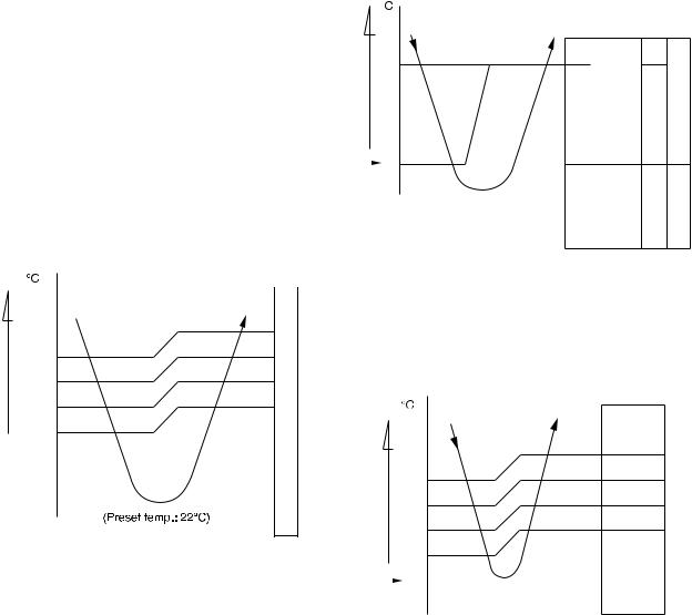
7-2. Description of Operation Circuit
(1)When turning on the breaker, the operation lamp blinks. This means that the power is on (or the power supply is cut off.)
(2)When pressing [START / STOP] button on the remote control, receiving beep sounds from the indoor unit, and the next operation is performed together with opening the vertical air flow louver.
(3)Once the operation mode is set, it is memorized in the microcontroller so that the previous operation can be effected thereafter simply by pressing [START / STOP] button.
7-2-1. Fan only operation
([MODE] button on the remote control is set to the fan only operation.)
(1)When [FAN] button is set to AUTO, the indoor fan motor operates as shown in Fig. 7-2-1. When [FAN] button is set to LOW, LOW+, MED, MED+ or HIGH, the motor operates with a constant air flow.
FILE NO. SVM-04031
7-2-2. Cooling operation
([MODE] button on the remote control is set to the cooling operation.)
(1)The compressor, 4-way valve, outdoor fan and operation display on the remote control are controlled as shown in Fig. 7-2-2.
temp.) |
|
|
|
|
|
|
(Preset |
0.5 |
|
|
ON |
|
|
|
|
|
||||
|
|
ON |
|
|
|
|
temp.) — |
|
OFF |
ON |
OFF OFF ON |
||
(Room |
|
|||||
|
|
|
|
|
|
|
Preset |
|
0 |
Common relay |
|
|
|
|
|
|
|
|||
temp. |
|
Compressor |
4-way valve |
Outdoor fan |
OPERATION display |
|
|
|
|||||
|
|
|
|
|
|
|
temp.) |
+3 |
|
|
|
|
||
(Preset— |
|
M+ |
|
+2 |
|
||
|
+2.5 |
|
|
|
|
*1 |
|
temp.) |
*1 |
||
*1 |
|||
(Room |
+1.5 |
|
|
+0.5 |
|
|
|
|
+1 |
|
L— |
|
|
|
|
Preset  0 temp.
NOTE :
*1: The values marked with *1 are calculated and controlled by the difference in motor speed between M+ and L–.
Fig. 7-2-1 Setting of air flow [FAN:AUTO]
(2) ECO and Hi Power operation cannot be set.
Fig. 7-2-2
(2)When [FAN] button is set to AUTO, the indoor fan motor operates as shown in Fig. 7-2-3. When [FAN] button is set to LOW, LOW+, MED, MED+ or HIGH, the motor operates with a constant air flow.
temp.) |
+3 |
||
|
|||
(Preset |
|
M+ |
|
+2.5 |
|||
|
|||
|
*1 |
||
— |
+2 |
||
*1 |
|||
temp.) |
|||
+1.5 |
|||
|
|||
|
*1 |
||
(Room |
+1 |
||
|
L— |
||
|
+0.5 |
||
Preset |
|
0 |
|
|
|||
temp. |
-0.5 |
||
|
|||
NOTE :
*1: The values marked with *1 are calculated and controlled by the difference in motor speed between M+ and L–.
Fig. 7-2-3 Setting of air flow [FAN:AUTO]
– 23 –
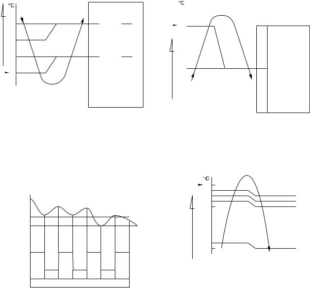
7-2-3. Dry operation
([MODE] button on the remote control is set to the dry operation.)
(1)The compressor, 4-way valve, outdoor fan and operation display on the remote control are controlled as shown in Fig. 7-2-4.
FILE NO. SVM-04031
7-2-4. Heating operation *Heating and cooling model only
([MODE] button on the remote control is set to the heating operation.)
(1)The compressor, 4-way valve, outdoor fan and operation display on the remote control are controlled as shown in Fig. 7-2-6.
(Preset—temp.)temp.) |
+3 |
ON:5min.ON:6min. OFF:5min.OFF:4min. |
|
|
ON:5min.ON:6min. OFF:5min.OFF:4min. |
|
|
|
|
|
|||||
|
|
|
|
|
|
||
(Room |
+2 |
|
ON |
OFF |
|
ON |
|
+1 |
|
|
|
|
|
||
|
|
|
|
|
|
||
|
|
|
OFF |
|
|
OFF |
|
Preset |
|
0 |
|
|
|
|
|
|
Compressor |
relayCommon |
valveway-4 |
fanOutdoor |
OPERATION display |
||
temp. |
|
|
|||||
|
|
|
|
|
|
|
|
|
|
|
|
|
|
|
|
Fig. 7-2-4
(2)The microcontroller turns the compressor on and off at the regular intervals (4 to 6 minutes). While the compressor is turning off, the indoor fan motor operates in the SUPER LOW position.
The pattern of operation depending on the relation between room temperature and preset temperatures is shown in Fig. 7-2-5.
Room temp.
Preset temp.+1
Preset temp.
Compressor |
ON |
ON |
|
ON |
|
ON |
|
|
|
|
|
|
|
|
|
Outdoor fan |
|
OFF |
|
OFF |
OFF |
||
|
|
|
|||||
Indoor fan |
|
|
|
|
|
|
|
L. |
*S.L. |
L. |
S.L. |
L. |
S.L. |
L. |
|
|
*Super Low |
|
|
|
|
|
|
Fig. 7-2-5
(3)[FAN] button on the remote control is set to AUTO only.
(4)The ECO and Hi POWER operations can not be set.
Preset |
|
0 |
|
|
|
|
|
|
temp. |
|
|
|
|
|
|
|
|
temp.) |
|
|
|
OFF ON |
ON |
OFF |
ON |
|
— (Preset |
|
|
|
|||||
-0.5 |
|
Compressor |
relayCommon |
valveway-4 |
|
OPERATION display |
||
|
fanOutdoor |
|||||||
(Roomtemp.) |
|
|
|
|||||
|
|
|
|
ON |
|
|
ON |
|
|
|
|
|
|
|
|
|
|
Fig. 7-2-6
(2)When [FAN] button is set to AUTO, the indoor fan motor operates as shown in Fig. 7-2-7. When [FAN] button is set to LOW, LOW+, MED, MED+ or HIGH, the motor operates with a constant air flow.
Preset |
|
0 |
L |
|
|
||||
temp. |
-0.5 |
*2 |
||
temp.) |
-1.5 |
|||
|
-1 |
*1 |
||
|
|
|
||
(Preset |
-2 |
|
||
|
|
M+ |
||
temp.) — |
|
|
||
-5.0 |
|
|||
(Room |
-5.5 |
H |
||
[FAN AUTO] |
||||
|
||||
|
|
|||
*1, *2 : The values marked with *1 and *2 are calculated and controlled by the difference in motor speed between M+ and L.
Fig. 7-2-7 Setting of air flow [FAN:AUTO]
– 24 –
Loading...