


 Loading...
Toshiba RAS-18UA-AS3, RAS-24UKP-AS3, RAS-24UAH-ES3, RAS-24UAH-AS3, RAS-18UAH-AS3 SERVICE MANUAL
...FILE NO. SVM-04007-(1)
SERVICE MANUAL
AIR CONDITIONER
SPLIT WALL TYPE
RAS-24UKHP-ES3 / RAS-24UAH-ES3
RAS-18UKHP-ES3 / RAS-18UAH-ES3
RAS-24UKP-ES3 / RAS-24UA-ES3
RAS-18UKP-ES3 / RAS-18UA-ES3
RAS-24UKHP-AS3 / RAS-24UAH-AS3
RAS-18UKHP-AS3 / RAS-18UAH-AS3
RAS-24UKP-AS3 / RAS-24UA-AS3
RAS-18UKP-AS3 / RAS-18UA-AS3
|
|
|
|
|
|
|
|
|
|
|
|
|
|
|
|
|
|
|
|
|
|
18 Class |
18 Class |
24 Class |
|||
(Heat pump model) |
(Cooling only model) |
|
|
|
||
May 2004
FILE NO. SVM-04007-(1)
CONTENTS
1.SPECIFICATIONS
2.CONSTRUCTION VIEWS
2-1 Indoor Unit
2-2 Outdoor Unit (RAS-24UAH-ES3, RAS-24UA-ES3, RAS-24UAH-AS3, RAS-24UA-AS3) 2-3 Outdoor Unit (RAS-18UAH-ES3, RAS-18UAH-AS3)
2-4 Outdoor Unit (RAS-18UA-ES3, RAS-18UA-AS3)
3.WIRING DIAGRAM
3-1 RAS-24UKHP-ES3 / RAS-24UAH-ES3, RAS-24UKHP-AS3 / RAS-24UAH-AS3 3-2 RAS-18UKHP-ES3 / RAS-18UAH-ES3, RAS-18UKHP-AS3 / RAS-18UAH-AS3 3-3 RAS-24UKP-ES3 / RAS-24UA-ES3, RAS-24UKP-AS3 / RAS-24UA-AS3
3-4 RAS-18UKP-ES3 / RAS-18UA-ES3, RAS-18UKP-AS3 / RAS-18UA-AS3
4.SPECIFICATION OF ELECTRICAL PARTS
4-1 Indoor Unit (RAS-24UKHP-ES3, RAS-18UKHP-ES3, RAS-24UKHP-AS3, RAS-18UKHP-AS3) 4-2 Outdoor Unit (RAS-24UAH-ES3, RAS-24UAH-AS3)
4-3 Outdoor Unit (RAS-18UAH-ES3, RAS-18UAH-AS3)
4-4 Indoor Unit (RAS-24UKP-ES3, RAS-18UKP-ES3, RAS-24UKP-AS3, RAS-18UKP-AS3) 4-5 Outdoor Unit (RAS-24UA-ES3, RAS-24UA-AS3)
4-6 Outdoor Unit (RAS-18UA-ES3, RAS-18UA-AS3)
5.REFRIGERATION CYCLE DIAGRAM
5-1 RAS-24UKHP-ES3 / RAS-24UAH-ES3, RAS-24UKHP-AS3 / RAS-24UAH-AS3
5-2 RAS-18UKHP-ES3 / RAS-18UAH-ES3, RAS-18UKHP-AS3 / RAS-18UAH-AS3 5-3 RAS-24UKP-ES3 / RAS-24UA-ES3, RAS-24UKP-AS3 / RAS-24UA-AS3
5-4 RAS-18UKP-ES3 / RAS-18UA-ES3, RAS-18UKP-AS3 / RAS-18UA-AS3
6.CONTROL BLOCK DIAGRAM
6-1 RAS-24UKHP-ES3, RAS-18UKHP-ES3, RAS-24UKHP-AS3, RAS-18UKHP-AS3 6-2 RAS-24UKP-ES3, RAS-18UKP-ES3, RAS-24UKP-AS3, RAS-18UKP-AS3
7.OPERATION DESCRIPTION
7-1 Outline of Air Conditioner Control
7-2 Description of Operation Circuit
7-3 Hi POWER Mode
7-4 High-Temperature Limit Control
7-5 Low-Temperature Limit Control
7-6 Defrosting Operation
7-7 Auto Restart Function
7-8 Filter Check Lamp
7-9 Self-Cleaning function
8.INSTALLATION PROCEDURE
8-1 Safety Cautions
8-2 Installation Diagram of Indoor and Outdoor Units 8-3 Installation
8-4 Indoor Unit
8-5 Outdoor Unit
8-6 Others
-1 -

FILE NO. SVM-04007
9.TROUBLESHOOTING CHART
9-1 Troubleshooting Procedure
9-2 Basic Check Items
9-3 Primary Judgement
9-4 Self-Diagnosis by Remote Control (Check Code) 9-5 How to Diagnose Faulty Part
9-6 Troubleshooting for Indoor Unit
9-7 Troubleshooting for Wiring (Interconnect cable and Serial Signal Wire) 9-8 Troubleshooting for P.C. Board
9-9 Troubleshooting for Remote Control
10.PARTS REPLACEMENT
10-1 Indoor Unit
10-2 Outdoor Unit (RAS-24UAH-ES3, RAS-24UA-ES3, RAS-24UAH-AS3, RAS-24UA-AS3) 10-3 Outdoor Unit (RAS-18UAH-ES3, RAS-18UAH-AS3)
10-4 Outdoor Unit (RAS-18UA-ES3, RAS-18UA-AS3)
11.EXPLODED VIEWS AND PARTS LIST
11-1 Indoor Unit (E - Parts Assy)
11-2 Indoor Unit
11-3 Outdoor Unit (RAS-24UAH-ES3, RAS-24UAH-AS3) 11-4 Outdoor Unit (RAS-18UAH-ES3, RAS-18UAH-AS3) 11-5 Outdoor Unit (RAS-24UA-ES3, RAS-24UA-AS3)
11-6 Outdoor Unit (RAS-18UA-ES3, RAS-18UA-AS3)
∙This air conditioner is charged with HFC (R410A) that doesn't deplete the Ozone layer.
∙This air conditioner requires special installation for the refrigerant R410A.
- 2 -

FILE NO. SVM-04007
1. SPECIFICATIONS
|
MODEL |
RAS-24UKHP-ES3 |
RAS-24UKP-ES3 |
RAS-18UKHP-ES3 |
RAS-18UKP-ES3 |
||||||||||
|
RAS-24UAH-ES3 |
RAS-24UA-ES3 |
RAS-18UAH-ES3 |
RAS-18UA-ES3 |
|||||||||||
|
|
|
|||||||||||||
ITEM |
|
|
Cooling |
Heating |
Cooling |
Cooling |
Heating |
Cooling |
|||||||
Capacity |
|
|
220V 240V 220V 240V |
220V |
240V |
220V 240V 220V 240V |
220V |
240V |
|||||||
|
kW |
6.30 |
6.30 |
6.80 |
6.90 |
6.80 |
6.85 |
5.00 |
5.05 |
5.45 |
5.55 |
5.30 |
5.35 |
||
|
|
||||||||||||||
|
|
Phase |
|
|
|
|
|
1 |
|
|
|
|
|
||
Power source |
|
V |
|
|
|
|
|
220 - 240 |
|
|
|
|
|
||
|
|
Hz |
|
|
|
|
|
50 |
|
|
|
|
|
||
Power consumption |
|
W |
2430 2510 2400 2480 |
2560 |
2690 |
1850 1900 1648 1718 |
1860 |
1960 |
|||||||
Power factor |
|
% |
96 |
92 |
95 |
90 |
94 |
89 |
98 |
97 |
94 |
92 |
98 |
97 |
|
|
|
|
220V 240V 220V 240V |
220V |
240V |
220V 240V 220V 240V |
220V |
240V |
|||||||
Running current |
|
A |
0.3/ |
0.3/ |
0.3/11.2 |
0.3/12.1 |
0.3/12.35 |
0.2/ |
0.2/ |
0.2/ |
0.2/ |
0.2/8.5 |
0.2/8.3 |
||
|
Indoor/Outdoor |
11.2 |
11.1 |
|
|
|
|
8.4 |
8.0 |
7.9 |
7.7 |
|
|
||
Starting current |
|
A |
|
|
|
65 |
|
|
|
47 |
|
|
33 |
||
Moisture removal |
|
lit/h |
|
2.5 |
|
|
2.7 |
|
2.0 |
|
|
2.0 |
|||
Noise |
Indoor (H/M/L) |
dB |
|
|
|
45/41/37 |
|
|
|
|
42/39/35 |
|
|||
Outdoor (220-240V) |
dB |
56-57 |
57-58 |
56-57 |
51-52 |
52-53 |
51-52 |
||||||||
|
|||||||||||||||
Refrigerant |
Name of refrigerant |
|
|
|
|
|
|
R410A |
|
|
|
|
|
||
Rated amount |
kg |
|
|
|
1.6 |
|
|
|
1.3 |
|
|
1.2 |
|||
|
|
|
|
|
|
|
|
|
|||||||
Refrigerant control |
|
|
|
|
|
|
|
|
|
|
Capillary tube |
|
|
|
|
|
|
|
|||
|
Gas side size |
mm |
|
|
|
|
|
|
|
|
|
12.7 |
|
|
|
|
|
|
|
||
|
|
|
|
|
|
|
|
|
|
|
|
|
|
|
|
|
|
|
|
|
|
|
Connection type |
|
|
|
|
|
|
|
|
|
Flare connection |
|
|
|
|
|
|
|
|||
|
Liquid side size |
mm |
|
|
|
|
|
|
|
|
|
6.35 |
|
|
|
|
|
|
|
||
Interconnection |
Connection type |
|
|
|
|
|
|
|
|
|
Flare connection |
|
|
|
|
|
|
|
|||
pipe |
Maximum length |
m |
|
|
|
|
|
|
|
|
|
15*1 |
|
|
|
|
|
|
|
|
|
|
(One way) |
|
|
25*2 |
|
|
|
|
|
|
20*2 |
|
|
|
|||||||
|
|
|
|
|
|
|
|
|
|
|
|
|
|||||||||
|
Maximum height |
m |
|
|
10 |
|
|
|
|
|
|
8 |
|
|
|
||||||
|
difference |
|
|
|
|
|
|
|
|
|
|
|
|||||||||
|
|
|
|
|
|
|
|
|
|
|
|
|
|
|
|
|
|
|
|
|
|
INDOOR UNIT |
|
|
RAS-24UKHP-ES3 |
|
RAS-24UKP-ES3 |
|
RAS-18UKHP-ES3 |
|
RAS-18UKP-ES3 |
||||||||||||
|
Height |
mm |
|
|
|
|
|
|
|
|
|
298 |
|
|
|
|
|
|
|
|
|
|
|
|
|
|
|
|
|
|
|
|
|
|
|
|
|
|
|
|
|
|
|
Dimensions |
Width |
mm |
|
|
|
|
|
|
|
|
|
998 |
|
|
|
|
|
|
|
|
|
|
Depth |
mm |
|
|
|
|
|
|
|
|
|
208 |
|
|
|
|
|
|
|
|
|
Net weight |
|
kg |
|
|
|
|
|
|
|
|
|
12 |
|
|
|
|
|
|
|
|
|
|
|
|
|
|
|
|
|
|
|
|
|
|
|
|
|
|
|
|
|
|
|
Evaporator type |
|
|
|
|
|
|
|
|
|
|
Finned tube |
|
|
|
|
|
|
|
|||
|
|
|
|
|
|
|
|
|
|
|
|
|
|
|
|
|
|
|
|
|
|
Indoor fan type |
|
|
|
|
|
|
|
|
|
|
Cross flow fan |
|
|
|
|
|
|
|
|||
|
High fan |
m3/h |
950 |
|
950 |
|
|
950 |
|
750 |
|
800 |
|
|
750 |
||||||
Air volume |
Medium fan |
m3/h |
750 |
|
800 |
|
|
750 |
|
650 |
|
700 |
|
|
650 |
||||||
|
Low fan |
m3/h |
600 |
|
650 |
|
|
600 |
|
530 |
|
570 |
|
|
530 |
||||||
Fan motor output |
|
W |
|
|
|
|
|
|
|
|
|
20 |
|
|
|
|
|
|
|
|
|
Air filter |
|
|
|
|
|
|
|
|
Honeycomb woven filter with PP frame |
|
|
|
|||||||||
OUTDOOR UNIT |
|
|
RAS-24UAH-ES3 |
|
RAS-24UA-ES3 |
|
RAS-18UAH-ES3 |
|
RAS-18UA-ES3 |
||||||||||||
|
|
|
|
|
|
|
|
|
|
|
|
|
|
|
|
|
|
|
|
|
|
|
Height |
mm |
|
|
690 |
|
|
|
|
|
|
538 |
|
|
|
||||||
|
|
|
|
|
|
|
|
|
|
|
|
|
|
|
|
|
|
|
|
|
|
Dimensions |
Width |
mm |
|
|
880 |
|
|
|
|
|
|
830 |
|
|
|
780 |
|||||
|
Depth |
mm |
|
|
310 |
|
|
|
|
|
|
300 |
|
|
|
||||||
Net weight |
|
kg |
|
|
69 |
|
|
|
63 |
|
|
|
50 |
|
|
|
41 |
||||
|
|
|
|
|
|
|
|
|
|
|
|
|
|
|
|
|
|
|
|
|
|
Condenser type |
|
|
|
|
|
|
|
|
|
|
Finned tube |
|
|
|
|
|
|
|
|||
|
|
|
|
|
|
|
|
|
|
|
|
|
|
|
|
|
|
|
|
|
|
Outdoor fan type |
|
|
|
|
|
|
|
|
|
|
Propeller fan |
|
|
|
|
|
|
|
|||
Airflow volume |
|
m3/h |
3380 |
3560 |
3380 |
3560 |
|
3380 |
|
3560 |
|
1800 |
2000 |
1800 |
2000 |
|
1800 |
|
2000 |
||
Fan motor output |
|
W |
|
|
65 |
|
|
|
|
|
|
42 |
|
|
|
||||||
|
|
|
|
|
|
|
|
|
|
|
|
|
|
|
|
|
|
||||
Compressor |
Model |
|
PA290X3F-4MS |
|
5JS315DAG01 |
|
PA225X3F-4L |
|
5KS225DAA |
||||||||||||
Output |
W |
|
|
2200 |
|
|
|
|
|
|
1500 |
|
|
|
|||||||
|
|
|
|
|
|
|
|
|
|
|
|
||||||||||
Safety device |
|
|
IOL, Td Sensor |
|
|
IOL |
|
IOL, Td Sensor |
|
|
IOL |
||||||||||
Louver type |
|
|
|
|
|
|
|
|
|
|
Automatic louver |
|
|
|
|
|
|
|
|||
|
|
|
|
|
|
|
|
|
|
|
|
|
|
|
|
|
|
|
|||
Usable outdoor temperature range |
°C |
15 ~ 43 |
|
-10 ~ 24 |
|
15 ~ 43 |
|
15 ~ 43 |
|
-10 ~ 24 |
|
15 ~ 43 |
|||||||||
- 3 -
FILE NO. SVM-04007
|
MODEL |
RAS-24UKHP-AS3 |
RAS-24UKP-AS3 |
RAS-18UKHP-AS3 |
RAS-18UKP-AS3 |
||||||||||
|
RAS-24UAH-AS3 |
RAS-24UA-AS3 |
RAS-18UAH-AS3 |
RAS-18UA-AS3 |
|||||||||||
|
|
|
|||||||||||||
ITEM |
|
|
Cooling |
Heating |
Cooling |
Cooling |
Heating |
Cooling |
|||||||
Capacity |
|
|
220V 240V 220V 240V |
220V |
240V |
220V 240V 220V 240V |
220V |
240V |
|||||||
|
kW |
6.30 |
6.30 |
6.80 |
6.90 |
6.80 |
6.85 |
5.00 |
5.05 |
5.45 |
5.55 |
5.30 |
5.35 |
||
|
|
||||||||||||||
|
|
Phase |
|
|
|
|
|
1 |
|
|
|
|
|
||
Power source |
|
V |
|
|
|
|
|
220 - 240 |
|
|
|
|
|
||
|
|
Hz |
|
|
|
|
|
|
50 |
|
|
|
|
|
|
Power consumption |
|
W |
2430 2510 2405 2500 |
2560 |
2690 |
1850 1900 1648 1718 |
1860 |
1960 |
|||||||
Power factor |
|
% |
96 |
92 |
95 |
91 |
94 |
89 |
98 |
97 |
94 |
92 |
98 |
97 |
|
|
|
|
220V 240V 220V 240V |
220V |
240V |
220V 240V 220V 240V |
220V |
240V |
|||||||
Running current |
|
A |
0.3/ |
0.3/ |
0.3/ |
0.3/ |
0.3/12.9 |
0.3/12.35 |
0.2/ |
0.2/ |
0.2/ |
0.2/ |
0.2/8.5 |
0.2/8.3 |
|
|
Indoor/Outdoor |
11.2 |
11.1 |
11.2 11.20 |
|
|
8.4 |
8.0 |
7.9 |
7.7 |
|
|
|||
Starting current |
|
A |
|
|
|
45 |
|
|
|
43 |
|
|
33 |
||
Moisture removal |
|
lit/h |
|
2.5 |
|
|
2.7 |
|
2.0 |
|
|
2.0 |
|||
Noise |
Indoor (H/M/L) |
dB |
|
|
|
45/41/37 |
|
|
|
|
42/39/35 |
|
|||
Outdoor (220-240V) |
dB |
56-57 |
57-58 |
56-57 |
51-52 |
52-53 |
51-52 |
||||||||
|
|||||||||||||||
Refrigerant |
Name of refrigerant |
|
|
|
|
|
|
R410A |
|
|
|
|
|
||
Rated amount |
kg |
|
|
|
1.6 |
|
|
|
1.3 |
|
|
1.14 |
|||
|
|
|
|
|
|
|
|
|
|||||||
Refrigerant control |
|
|
|
|
|
|
|
|
|
|
|
Capillary tube |
|
|
|
|
|
|
|
|||
|
Gas side size |
mm |
|
|
|
|
|
|
|
|
|
|
12.7 |
|
|
|
|
|
|
|
||
|
|
|
|
|
|
|
|
|
|
|
|
|
|
|
|
|
|
|
|
|
|
|
|
Connection type |
|
|
|
|
|
|
|
|
|
|
Flare connection |
|
|
|
|
|
|
|
|||
|
Liquid side size |
mm |
|
|
|
|
|
|
|
|
|
|
6.35 |
|
|
|
|
|
|
|
||
Interconnection |
Connection type |
|
|
|
|
|
|
|
|
|
|
Flare connection |
|
|
|
|
|
|
|
|||
pipe |
Maximum length |
m |
|
|
|
|
|
|
|
|
|
|
15*1 |
|
|
|
|
|
|
|
|
|
|
(One way) |
|
|
25*2 |
|
|
|
|
|
|
20*2 |
|
|
|
||||||||
|
|
|
|
|
|
|
|
|
|
|
|
|
||||||||||
|
Maximum height |
m |
|
|
10 |
|
|
|
|
|
|
8 |
|
|
|
|||||||
|
difference |
|
|
|
|
|
|
|
|
|
|
|
||||||||||
|
|
|
|
|
|
|
|
|
|
|
|
|
|
|
|
|
|
|
|
|
|
|
INDOOR UNIT |
|
|
RAS-24UKHP-AS3 |
|
RAS-24UKP-AS3 |
|
RAS-18UKHP-AS3 |
|
RAS-18UKP-AS3 |
|||||||||||||
|
Height |
mm |
|
|
|
|
|
|
|
|
|
|
298 |
|
|
|
|
|
|
|
|
|
|
|
|
|
|
|
|
|
|
|
|
|
|
|
|
|
|
|
|
|
|
|
|
Dimensions |
Width |
mm |
|
|
|
|
|
|
|
|
|
|
998 |
|
|
|
|
|
|
|
|
|
|
Depth |
mm |
|
|
|
|
|
|
|
|
|
|
208 |
|
|
|
|
|
|
|
|
|
Net weight |
|
kg |
|
|
|
|
|
|
|
|
|
|
12 |
|
|
|
|
|
|
|
|
|
Evaporator type |
|
|
|
|
|
|
|
|
|
|
|
|
- |
|
|
|
|
|
|
|
|
|
|
|
|
|
|
|
|
|
|
|
|
Finned tube |
|
|
|
|
|
|
|
||||
Indoor fan type |
|
|
|
|
|
|
|
|
|
|
|
Cross flow fan |
|
|
|
|
|
|
|
|||
|
High fan |
m3/h |
950 |
|
950 |
|
|
|
950 |
|
750 |
|
800 |
|
|
750 |
||||||
Air volume |
Medium fan |
m3/h |
750 |
|
800 |
|
|
|
750 |
|
650 |
|
700 |
|
|
650 |
||||||
|
Low fan |
m3/h |
600 |
|
650 |
|
|
|
600 |
|
530 |
|
570 |
|
|
530 |
||||||
Fan motor output |
|
W |
|
|
|
|
|
|
|
|
|
|
30 |
|
|
|
|
|
|
|
|
|
Air filter |
|
|
|
|
|
|
|
|
|
Honeycomb woven filter with PP frame |
|
|
|
|||||||||
OUTDOOR UNIT |
|
|
RAS-24UAH-AS3 |
|
RAS-24UA-AS3 |
|
RAS-18UAH-AS3 |
|
RAS-18UA-AS3 |
|||||||||||||
|
|
|
|
|
|
|
|
|
|
|
|
|
|
|
|
|
|
|
|
|
|
|
|
Height |
mm |
|
|
690 |
|
|
|
|
|
|
538 |
|
|
|
|||||||
|
|
|
|
|
|
|
|
|
|
|
|
|
|
|
|
|
|
|
|
|
|
|
Dimensions |
Width |
mm |
|
|
880 |
|
|
|
|
|
|
830 |
|
|
|
780 |
||||||
|
Depth |
mm |
|
|
310 |
|
|
|
|
|
|
300 |
|
|
|
|||||||
Net weight |
|
kg |
|
|
64 |
|
|
|
|
67 |
|
|
|
51 |
|
|
|
41 |
||||
|
|
|
|
|
|
|
|
|
|
|
|
|
|
|
|
|
|
|
|
|
|
|
Condenser type |
|
|
|
|
|
|
|
|
|
|
|
Finned tube |
|
|
|
|
|
|
|
|||
|
|
|
|
|
|
|
|
|
|
|
|
|
|
|
|
|
|
|
|
|
|
|
Outdoor fan type |
|
|
|
|
|
|
|
|
|
|
|
Propeller fan |
|
|
|
|
|
|
|
|||
Airflow volume |
|
m3/h |
3380 |
3560 |
3380 |
3560 |
|
|
3380 |
|
3560 |
|
1800 |
2000 |
1800 |
2000 |
|
1830 |
|
2010 |
||
Fan motor output |
|
W |
|
|
65 |
|
|
|
|
|
|
41 |
|
|
|
|||||||
|
|
|
|
|
|
|
|
|
|
|
|
|
|
|
|
|
|
|
||||
Compressor |
Model |
|
PA290X3F-4MS |
|
|
5JS315DAG01 |
|
PA225X3F-4L |
|
5KS225DAA |
||||||||||||
Output |
W |
|
|
2200 |
|
|
|
|
|
|
1500 |
|
|
|
||||||||
|
|
|
|
|
|
|
|
|
|
|
|
|||||||||||
Safety device |
|
|
IOL, Td Sensor |
|
|
IOL |
|
IOL, Td Sensor |
|
|
IOL |
|||||||||||
Louver type |
|
|
|
|
|
|
|
|
|
|
|
Automatic louver |
|
|
|
|
|
|
|
|||
|
|
|
|
|
|
|
|
|
|
|
|
|
|
|
|
|
|
|
|
|||
Usable outdoor temperature range |
°C |
15 ~ 43 |
|
-10 ~ 24 |
|
|
15 ~ 43 |
|
15 ~ 43 |
|
-10 ~ 24 |
|
15 ~ 43 |
|||||||||
– 4 –
FILE NO. SVM-04007
Note : 1
· Capacity is based on the following temperature conditions.
|
Condition |
|
JIS C9612-1994 |
|
Temperature |
Cooling |
Heating |
||
|
||||
Indoor unit inlet air temperature |
(DB) |
27°C |
20°C |
|
(WB) |
19°C |
15°C |
||
|
||||
Outdoor unit inlet air temperature |
(DB) |
35°C |
7°C |
|
(WB) |
24°C |
6°C |
||
|
Note : 2
· Charge refrigerant according to the table below.
|
Refrigerant |
RAS-24UKHP-ES3 / RAS-24UAH-ES3 |
RAS-18UKHP-ES3 / RAS-18UAH-ES3 |
|
RAS-24UKP-ES3 / RAS-24UA-ES3 |
RAS-18UKP-ES3 / RAS-18UA-ES3 |
|
|
|
||
|
|
RAS-24UKHP-AS3 / RAS-24UAH-AS3 |
RAS-18UKHP-AS3 / RAS-18UA-AS3 |
|
|
RAS-24UKP-AS3 / RAS-24UA-AS3 |
RAS-18UKP-AS3 / RAS-18UA-AS3 |
*1 |
No need to charge |
15m or less |
15m or less |
|
extra refrigerant |
||
|
|
|
|
|
|
|
|
*2 |
Need to charge |
Over 15m up to 25m (20g/m) |
Over 15m up to 20m (20g/m) |
|
extra refrigerant |
||
|
|
|
|
|
|
|
|
- 5 -

FILE NO. SVM-04007
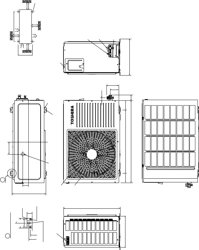
2. CONSTRUCTION VIEWS
2-1. Indoor Unit
Back body |
|
|
Front panel |
998 |
208 |
Grille inlet |
|
|
298 |
|
|
75 |
|
75 |
7 |
|
8 |
51 |
|
50 |
Knock out system |
|
Knock out system |
|
50 |
75 |
56 |
|
|
|
|
|
|
|
|
160 |
|
|
Connection pipe (0.39m) |
|
Drain hose (0.54m) |
57 |
18 |
||
|
|
(Flare |
12.7) |
|
Connection pipe (0.49m) |
Wireless remote control |
||
|
|
|
(Flare |
6.35) |
|
|
||
|
|
|
|
|
|
|
||
|
distance |
|
|
998 |
|
|
|
|
more |
|
|
763.5 |
|
(For stud bolt |
6) |
||
|
|
450 |
|
|||||
|
|
|
|
|
|
|||
55 or |
Minimum to ceiling |
|
20 |
20 |
|
|
|
|
|
48 |
10 |
|
29 |
|
|
||
Outline of indoor unit |
|
|
|
|
|
41 |
48 |
|
|
|
|
|
|
|
|
||
298 |
|
|
|
|
|
55 55 55 |
|
|
|
|
65 |
|
Installation |
|
|
|
|
|
|
100 |
100 |
6540 |
|
|
||
|
|
Plate outline |
|
|
|
|||
|
|
|
|
|
|
|
|
|
– 6 –
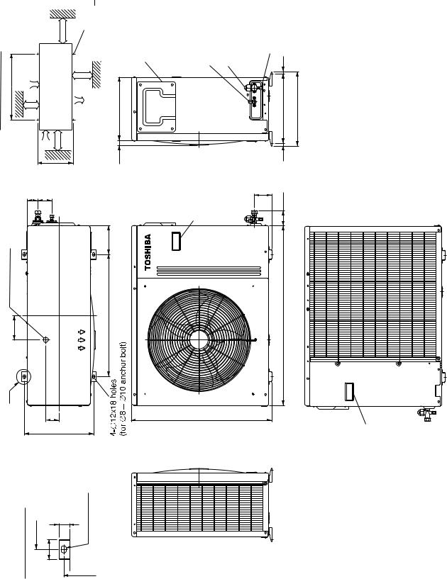
2-2. Outdoor Unit (RAS-24UAH-ES3, RAS-24UA-ES3,
RAS-24UAH-AS3, RAS-24UA-AS3)
dimensionInstallation 600 600 or more |
inletAir |
12X18 8 10 bolt |
310 |
|
outletAir |
anchor |
|||
|
|
4 - for |
|
|
|
|
600or more |
|
|
100 or more |
|
100 or more |
|
23 |
|
340 |
|
|
|
|
6852 |
outlet |
140 |
25 Drain |
|
|
|
120 |
600 |
A |
8.63 |
340 |
Electric Parts cover |
Liquid side (Flare 6.35) Gas side (Flare 1 2.7) |
Service Port |
12 |
|
|
|
340 (pitch) |
364 |
|
|
|
|
12 |
|
|
Handle |
88 |
74 |
|
|
|
|
||
|
|
|
880 |
|
|
690 |
|
|
|
DrawingDetail |
600 50 |
27 |
12x18 hole |
|
|
|
|
A |
|
|
|
|
|
|
340 |
FILE NO. SVM-04007
Handle
– 7 –
|
A Detail Drawing |
|
A |
120 |
|
|
|
|
|
||
|
50 |
600 |
|
|
|
|
35 |
R10 |
|
|
|
|
|
|
|
|
|
|
|
23 |
325 |
52 |
|
|
|
6 hole |
|
|
|
|
11x14 hole |
|
|
|
|
Handle |
|
|
420 |
8 – |
538 |
– |
|
|
300 |
Fan guard |
25 Drain outlet |
90 |
600 |
|
830 |
Installation dimension
100 or more |
|
600 |
|
|
|
Air inlet |
|
|
|
|
|
600 or more |
||
|
Air inlet |
|
||
325 |
|
|
|
|
|
600 or |
|
|
|
100 or more |
|
4x |
11x14 |
|
Air |
more |
|||
|
|
for |
8- 10 |
|
|
outlet |
|
anchor bolt |
|
8- 6 holes
(for fixing outdoor unit)
6- 11x14 holes
or 8 — 10 anchor bolt)
|
|
|
|
|
Electric |
|
|
|
|
|
|
Parts cover |
|
|
|
|
|
Service Port |
Liquid side |
|
|
|
|
|
(Flare |
6.35) |
|
|
|
|
|
|
||
|
|
|
54 |
|
Gas side |
|
|
|
|
|
(Flare |
12.7) |
|
|
|
|
91 |
|
||
|
|
|
|
|
|
|
90 |
50 |
60 |
|
|
344 |
|
AS3)-18UAH-RAS ES3,-18UAH-(RAS Unit Outdoor .3-2
04007-SVM .NO FILE
FILE NO. SVM-04007
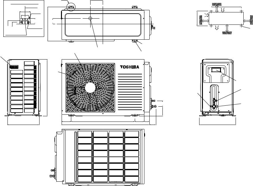
2-4. Outdoor Unit (RAS-18UA-ES3, RAS-18UA-AS3)
|
|
or more |
4x 11x14 or 8- 10 anchor bolt |
|
dimension |
|
600 |
|
|
600 inletAir |
600 |
|
||
|
|
|
or |
|
Installation |
|
Air inlet |
more |
|
more |
more |
outlet |
||
|
|
|
Air |
|
|
or |
|
or |
|
|
100 |
325 |
100 |
|
|
|
|
|
|
120
A
5.52
325
Electric parts cover
8- 6 hole25Drain outlet 4- 11x14 hole (for fixing outdoor unit) (for Ø8-Ø10 anchor bolt)
Fan guard
Liquid side (Flare 6.35) |
Gas side (Flare 12.7) |
Service Port |
344
27 |
130 |
100 |
|
|
65.5 |
90
600 |
780 |
90
420
DrawingDetail |
600 50 35 |
||
|
|
R10 |
|
|
|
|
|
|
|
|
|
A
23 |
6 hole |
|
301 325
11x14 hole
|
538 |
Handle |
300 |
– 9 –
FILE NO. SVM-04007
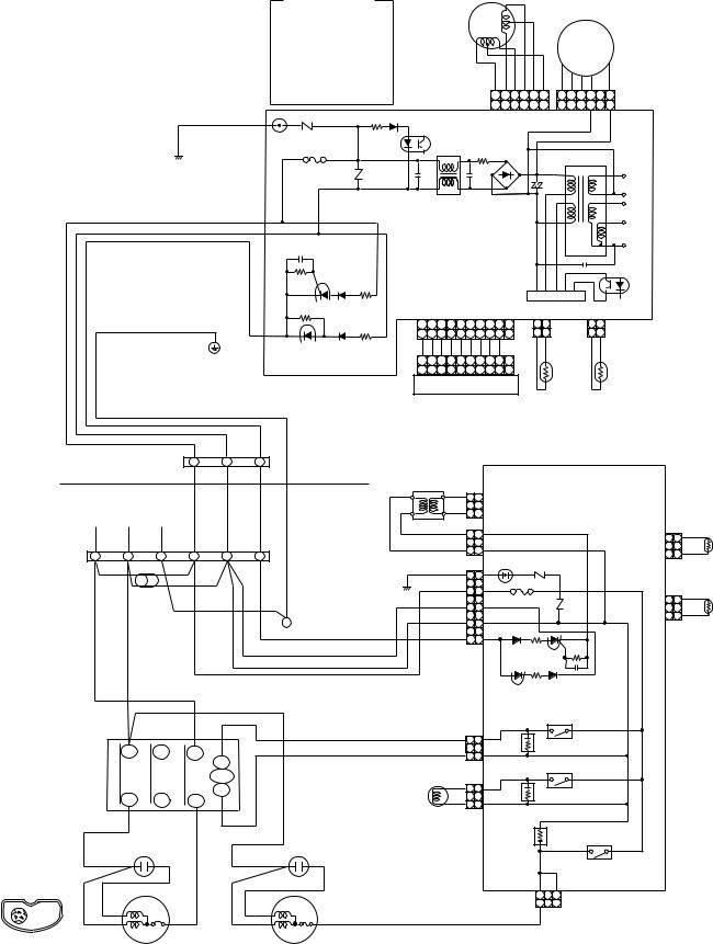
3. WIRING DIAGRAM
3-1. RAS-24UKHP-ES3 / RAS-24UAH-ES3 , RAS-24UKHP-AS3 / RAS-24UAH-AS3
COLOR IDENTIFICATION
BRW : BROWN
RED : RED
WHI : WHITE
YEL : YELLOW
BLU : BLUE
BLK : BLACK
GRY : GRAY
PNK : PINK
ORN : ORANGE
GRN&YEL : GREEN &YELLOW
GRN : GREEN
BLK |
|
R22 |
R09 |
P04 |
SG01 VARISTOR |
|
|
|
DSA |
T6. 3A 250V |
|
|
|
|
|
F01 FUSE
R21
BLK |
CN31 |
WHI |
CN30 |
RED |
|
GRN&YEL
CN23
LOUVER |
|
|
|
|
|
|
FAN MOTOR |
|||||
|
|
|
|
|
|
|
|
|
||||
MOTOR |
|
|
|
|
|
|
DC MOTOR |
|
||||
|
|
|
|
|
|
|
|
|
|
|
||
|
|
|
|
|
|
BLU PNK YEL ORN RED BRW |
6 5 4 3 |
|
||||
|
|
|
|
|
|
|
6 5 4 |
3 |
2 1 |
1 |
||
|
|
|
|
|
|
|
6 5 4 |
3 2 1 |
6 5 4 3 |
1 |
||
|
|
|
|
|
|
|
CN 07 |
|
CN 10 |
|
||
IC04 |
|
|
|
|
|
|
|
|
|
|
|
|
|
L01 |
|
|
R01 |
DB01 |
|
|
T01 |
|
|||
|
|
|
|
|
|
|
|
|||||
|
|
|
|
|
|
|
|
|
|
|
|
|
C15 |
|
|
|
C01 |
|
|
C02 |
|
DC15V |
|||
|
|
|
|
|
|
|
|
|
|
DC0V |
||
|
|
|
|
|
|
|
|
|
|
|
|
|
|
|
|
|
|
|
|
|
|
|
|
|
DC12V |
|
|
|
|
|
|
|
|
|
|
|
|
DC7V |
MAIN P.C. BOARD |
|
|
|
|
DC0V |
|||||||
|
|
C06 |
|
|||||||||
|
(MCC-821) |
|
|
|
||||||||
|
|
|
|
|
IC02 |
|||||||
|
|
|
|
|
|
|
|
|
|
|
|
|
|
|
|
|
|
|
|
|
|
|
IC |
|
|
|
|
CN13 |
|
|
|
|
CN03 IC01 |
CN01 |
|
|||
1 2 3 4 |
5 6 7 8 9 10 |
|
1 2 |
|
1 2 |
|
||||||
1 2 3 4 |
5 |
6 7 8 9 10 |
|
1 2 |
|
1 2 |
|
|||||
BLU BLU BLU BLU BLU BLU BLU BLU BLU WHI |
BLK BLK |
THERMOBLKBLK |
HEAT |
|||||||||
1 |
2 3 |
4 |
5 6 |
7 |
8 |
9 10 |
|
|
SENSOR |
|||
|
|
|
||||||||||
1 2 3 4 |
5 6 7 8 9 10CN25 |
(TA) |
|
EXCHANGER |
||||||||
INFRARED RAYS RECEIVE |
|
|
|
|
SENSOR |
|||||||
|
|
|
|
(TC) |
||||||||
AND INDICATION PARTS |
|
|
|
|
|
|||||||
INDOOR |
1 |
2 |
3 |
INDOOR |
|
|
TERMINAL |
|
|
|
|
|
|
|
|
|
UNIT |
|
MAIN P.C. BOARD (MCC-890) |
|
BLOCK |
|
|
|
TRANSFORMER |
||
|
|
|
|
|
|
|
|
|
|
|
|
|
|
|
OUTDOOR |
BLK 1 1 |
|
|
|
|
|
DISCHARGE |
|
|
|
POWER SUPPLY |
|
|
|
|
UNIT |
2 |
CN06 |
|
|
|
|
||||
|
|
220-240 V~ 50 Hz |
|
|
|
|
|
BLK 3 3 |
|
|
|
|
|
PIPE |
|||
|
|
|
|
|
|
|
|
|
|
|
|
|
SENSOR (TD) |
||||
|
|
|
|
|
|
|
|
|
|
RED 1 1 |
|
|
|
|
|
||
|
|
|
|
|
|
|
|
|
|
CN05 |
|
|
|
1 |
1 |
BLU |
|
|
OUTDOOR |
|
|
|
|
|
|
|
|
RED 3 3 |
|
|
CN07 2 |
|
|
||
|
TERMINAL |
L |
N |
i |
|
1 |
2 |
3 |
GRN&YEL |
|
SG01 |
TNR |
|
|
3 |
3 |
BLU |
|
BLOCK |
|
FERRITE CORE |
|
|
BLK 1 1 |
R74 |
|
|
|
|
|
|||||
|
|
|
|
|
|
|
|
|
|
|
|
||||||
|
|
BLK |
|
|
|
|
|
|
|
|
|
|
|
|
|
|
|
|
|
|
|
|
|
|
|
|
BLK 3 3 |
F01 |
|
|
|
|
|
||
|
|
|
RED |
|
|
|
|
|
|
|
|
|
|
|
|||
|
|
|
|
|
GRN&YEL |
|
|
250VAC T6. 3A |
TNR |
|
1 1 |
BLK |
|||||
|
|
|
|
|
|
|
|
WHI 5 5 |
CN08 |
||||||||
|
|
|
|
|
|
|
|
|
|
|
|
R73 |
2 |
|
|
||
|
|
|
|
|
|
|
|
|
i |
RED 7 7 |
CN01 |
|
|
|
3 |
3 |
BLK |
|
|
|
|
|
|
|
|
|
CHASSIS |
GRY 9 9 |
|
|
|
|
|
HEAT |
|
|
BLK |
RED |
|
|
|
|
|
|
|
|
|
|
EXCHANGER |
||||
|
|
|
|
|
|
|
|
|
|
|
|
||||||
|
|
|
|
|
|
|
|
|
|
|
|
|
SENSOR (TE) |
||||
|
|
|
|
|
|
|
|
|
|
|
|
|
|
|
|
||
|
|
|
MAGNETIC |
|
|
|
|
|
|
|
RY07 |
|
|
|
|
||
|
|
|
|
|
|
|
|
|
|
|
|
|
|
|
|||
|
|
|
CONTACTOR |
|
|
|
BLU 1 1 |
|
|
|
|
|
|
|
|||
|
|
|
|
|
|
|
|
|
|
CN11 |
|
|
|
|
|
|
|
|
|
|
R |
S |
|
T |
|
|
|
YEL 3 3 |
|
|
|
|
|
|
|
|
|
|
|
A1 |
|
|
|
CR11 |
RY05 |
|
|
|
|
||||
|
|
|
(1/L1) |
(3/L2) |
(5/L3) |
|
|
|
|
|
|
|
|
||||
|
|
|
(2/T1) |
(4/T2) |
(6/T3) |
52C |
|
|
BLU 1 1 |
|
|
|
|
|
|
|
|
|
|
|
A2 |
|
|
CN02 |
|
|
|
|
|
|
|||||
|
|
|
U |
V |
|
W |
|
|
|
BLU 3 3 |
CR12 |
|
|
|
|
|
|
|
|
|
|
|
|
|
|
|
|
COIL FOR |
|
|
|
|
|
|
|
|
|
|
|
|
|
|
|
|
|
|
|
|
|
|
|
|
|
|
|
|
|
|
|
|
|
|
|
4 WAY VALVE |
CR13 |
|
|
|
|
|
|
|
|
|
|
|
|
|
|
|
|
|
|
RY06 |
|
|
|
||
|
|
|
|
|
|
|
|
|
|
|
|
|
|
|
|
|
|
|
|
|
CAPACITOR |
|
|
|
|
CAPACITOR |
|
|
|
|
|
|
|
|
|
|
|
RED |
|
|
|
|
|
RED |
|
|
|
|
|
|
|
|
|
|
|
|
|
|
|
|
|
|
|
|
|
CN03 |
|
|
|
|
|
|
|
|
|
|
|
|
|
|
|
|
|
1 |
3 |
|
|
|
|
|
C |
WHI |
S |
|
|
|
|
WHI |
|
|
|
1 |
|
|
|
|
|
|
|
C |
BLK |
|
BLK |
|
|
BLK |
|
|
|
|
|
||||
S |
R |
PNK |
|
|
RED |
|
|
|
|
|
|
|
|||||
|
|
|
|
|
|
|
|
|
|
||||||||
COMPRESSOR TERMINAL |
|
R |
|
|
|
|
|
|
|
|
|
|
|
|
|
|
|
|
|
|
|
|
|
|
FAN MOTOR |
|
|
|
|
|
|
|
|
||
|
|
COMPRESSOR |
|
|
|
|
|
|
|
|
|
|
|
|
|||
– 10 –
FILE NO. SVM-04007
3-2. RAS-18UKHP-ES3 / RAS-18UAH-ES3, RAS-18UKHP-AS3 / RAS-18UAH-AS3
COLOR IDENTIFICATION
BRW : BROWN
RED : RED
WHI : WHITE
YEL : YELLOW
BLU : BLUE
BLK : BLACK
GRY : GRAY
PNK : PINK
ORN : ORANGE
GRN&YEL : GREEN &YELLOW
GRN : GREEN
BLK |
|
R22 |
R09 |
P04 |
SG01 VARISTOR |
|
|
|
DSA |
T6. 3A 250V |
|
|
|
|
|
F01 FUSE
R21
BLK |
CN31 |
WHI |
CN30 |
RED |
|
GRN&YEL
CN23
LOUVER |
|
|
|
|
|
|
FAN MOTOR |
|||||
|
|
|
|
|
|
|
|
|
||||
MOTOR |
|
|
|
|
|
|
DC MOTOR |
|
||||
|
|
|
|
|
|
|
|
|
|
|
||
|
|
|
|
|
|
BLU PNK YEL ORN RED BRW |
6 5 4 3 |
|
||||
|
|
|
|
|
|
|
6 5 4 |
3 |
2 1 |
1 |
||
|
|
|
|
|
|
|
6 5 4 |
3 2 1 |
6 5 4 3 |
1 |
||
|
|
|
|
|
|
|
CN 07 |
|
CN 10 |
|
||
IC04 |
|
|
|
|
|
|
|
|
|
|
|
|
|
L01 |
|
|
R01 |
DB01 |
|
|
T01 |
|
|||
|
|
|
|
|
|
|
|
|||||
|
|
|
|
|
|
|
|
|
|
|
|
|
C15 |
|
|
|
C01 |
|
|
C02 |
|
DC15V |
|||
|
|
|
|
|
|
|
|
|
|
DC0V |
||
|
|
|
|
|
|
|
|
|
|
|
|
|
|
|
|
|
|
|
|
|
|
|
|
|
DC12V |
|
|
|
|
|
|
|
|
|
|
|
|
DC7V |
MAIN P.C. BOARD |
|
|
|
|
DC0V |
|||||||
|
|
C06 |
|
|||||||||
|
(MCC-821) |
|
|
|
||||||||
|
|
|
|
|
IC02 |
|||||||
|
|
|
|
|
|
|
|
|
|
|
|
|
|
|
|
|
|
|
|
|
|
|
IC |
|
|
|
|
CN13 |
|
|
|
|
CN03 IC01 |
CN01 |
|
|||
1 2 3 4 |
5 6 7 8 9 10 |
|
1 2 |
|
1 2 |
|
||||||
1 2 3 4 |
5 |
6 7 8 9 10 |
|
1 2 |
|
1 2 |
|
|||||
BLU BLU BLU BLU BLU BLU BLU BLU BLU WHI |
BLK BLK |
THERMOBLKBLK |
HEAT |
|||||||||
1 |
2 3 |
4 |
5 6 |
7 |
8 |
9 10 |
|
|
SENSOR |
|||
|
|
|
||||||||||
1 2 3 4 |
5 6 7 8 9 10CN25 |
(TA) |
|
EXCHANGER |
||||||||
INFRARED RAYS RECEIVE |
|
|
|
|
SENSOR |
|||||||
|
|
|
|
(TC) |
||||||||
AND INDICATION PARTS |
|
|
|
|
|
|||||||
INDOOR |
1 |
2 |
3 |
INDOOR |
|
|
TERMINAL |
|
|
|
|
|
|
|
|
|
UNIT |
|
MAIN P.C. BOARD (MCC-890) |
|
BLOCK |
|
|
|
TRANSFORMER |
||
|
|
|
|
|
|
|
|
|
|
|
|
|
|
OUTDOOR |
BLK 1 1 |
|
|
|
|
|
DISCHARGE |
|
|
|
POWER SUPPLY |
|
|
|
UNIT |
2 |
CN06 |
|
|
|
|
||||
|
|
220-240 V~ 50 Hz |
|
|
|
|
BLK 3 3 |
|
|
|
|
|
PIPE |
|||
|
|
|
|
|
|
|
|
|
|
|
|
SENSOR (TD) |
||||
|
|
|
|
|
|
|
|
|
RED 1 1 |
|
|
|
|
|
||
|
|
|
|
|
|
|
|
|
CN05 |
|
|
|
1 |
1 |
BLU |
|
|
OUTDOOR |
|
|
|
|
|
|
|
RED 3 3 |
|
|
CN07 2 |
|
|
||
|
TERMINAL |
L |
N |
i |
1 |
2 |
3 |
GRN&YEL |
|
SG01 |
TNR |
|
|
3 |
3 |
BLU |
|
BLOCK |
|
FERRITE CORE |
|
|
BLK 1 1 |
R74 |
|
|
|
|
|
||||
|
|
|
|
|
|
|
|
|
|
|
|
|||||
|
|
BLK |
|
|
|
|
|
|
|
|
|
|
|
|
|
|
|
|
|
|
|
|
|
|
BLK 3 3 |
F01 |
|
|
|
|
|
||
|
|
|
|
RED |
|
|
|
|
|
|
|
|
|
|||
|
|
|
|
GRN&YEL |
|
|
250VAC T6. 3A |
TNR |
|
1 1 |
BLK |
|||||
|
|
|
|
|
|
|
WHI 5 5 |
CN08 |
||||||||
|
|
|
|
|
|
|
|
|
|
|
R73 |
2 |
|
|
||
|
|
|
|
|
|
|
|
i |
RED 7 7 |
CN01 |
|
|
|
3 |
3 |
BLK |
|
|
|
|
|
|
|
|
CHASSIS |
GRY 9 9 |
|
|
|
|
|
HEAT |
|
|
BLK |
RED |
|
|
|
|
|
|
|
|
|
EXCHANGER |
||||
|
|
|
|
|
|
|
|
|
|
|
||||||
|
|
|
|
|
|
|
|
|
|
|
|
SENSOR (TE) |
||||
|
|
|
|
|
|
|
|
|
|
|
|
|
|
|
||
|
|
|
|
MAGNETIC |
|
|
|
|
|
|
RY07 |
|
|
|
|
|
|
|
|
|
|
|
|
|
|
|
|
|
|
|
|
||
|
|
|
|
CONTACTOR |
|
|
|
BLU 1 1 |
|
|
|
|
|
|
|
|
|
|
|
|
|
|
|
|
|
CN11 |
|
|
|
|
|
|
|
|
|
|
R |
S |
T |
|
|
|
YEL 3 3 |
|
|
|
|
|
|
|
|
|
|
A1 |
|
|
|
|
|
|
|
|
|
||||
|
|
|
|
|
|
|
CR11 |
RY05 |
|
|
|
|
||||
|
|
|
|
|
|
52C |
|
|
|
|
|
|
|
|
|
|
|
|
|
|
|
|
|
|
BLU 1 1 |
|
|
|
|
|
|
|
|
|
|
|
U |
V |
W |
A2 |
|
|
CN02 |
|
|
|
|
|
|
|
|
|
|
|
|
|
BLU 3 3 |
CR12 |
|
|
|
|
|
||||
|
|
|
|
|
|
|
|
|
COIL FOR |
|
|
|
|
|
|
|
|
|
|
|
|
|
|
|
|
|
|
|
|
|
|
|
|
|
|
|
|
|
|
|
|
|
4 WAY VALVE |
CR13 |
|
|
|
|
|
|
|
|
|
|
|
|
|
|
|
|
|
RY06 |
|
|
|
||
|
|
|
|
|
|
|
|
|
|
|
|
|
|
|
|
|
|
|
|
CAPACITOR |
|
|
|
CAPACITOR |
|
|
|
|
|
|
|
|
|
|
|
RED |
|
|
|
|
RED |
|
|
|
|
|
|
|
|
|
|
|
|
|
|
|
|
|
|
|
|
CN03 |
|
|
|
|
|
|
|
|
|
|
|
|
|
|
|
|
1 |
3 |
|
|
|
|
|
C |
WHI |
S |
|
|
WHI |
|
|
|
1 |
|
|
|
|
|
|
|
|
|
|
|
|
|
|
|
|
|
|
|
||||
S |
R |
PNK |
|
C |
BLK |
|
RED |
BLK |
|
|
BLK |
|
|
|
|
|
|
|
|
|
|
|
|
|
|
|
|||||||
COMPRESSOR TERMINAL |
|
R |
|
|
|
|
|
|
|
|
|
|
|
|
||
|
|
|
|
|
|
FAN MOTOR |
|
|
|
|
|
|
|
|
||
|
|
COMPRESSOR |
|
|
|
|
|
|
|
|
|
|
|
|||
– 11 –

FILE NO. SVM-04007
3-3. RAS-24UKP-ES3 / RAS-24UA-ES3
COLOR IDENTIFICATION
BRW : BROWN
RED : RED
WHI : WHITE
YEL : YELLOW
BLU : BLUE
BLK : BLACK
GRY : GRAY
PNK : PINK
ORN : ORANGE
GRN&YEL : GREEN & YELLOW
GRN : GREEN
BLK |
R22 |
R09 |
P04 SG01 VARISTOR
DSA
T6.3A 250 V
F01 FUSE
R21
BLK |
CN30 |
WHI |
CN31 |
RED |
CN27 1 1 |
3 |
RY04 |
|
GRN&YEL
LOUVER |
|
|
|
|
|
FAN MOTOR |
|||||||
|
|
|
|
|
|
|
|
|
|||||
MOTOR |
|
|
|
|
|
DC MOTOR |
|
||||||
|
|
|
|
|
|
|
|
|
|
|
|||
|
|
|
|
|
|
BLU PNK YEL ORN RED BRW |
6 5 4 |
|
|
||||
|
|
|
|
|
|
|
6 5 4 |
3 |
2 1 |
3 |
1 |
||
|
|
|
|
|
|
|
6 5 4 |
3 2 1 |
6 5 4 |
3 |
1 |
||
|
|
|
|
|
|
|
CN 07 |
|
CN 10 |
|
|
||
IC04 |
|
|
|
|
|
|
|
|
|
|
|
|
|
|
|
L01 |
|
R01 |
DB01 |
|
|
T01 |
|
||||
|
|
|
|
|
|
|
|
|
|
|
|
||
C15 |
|
|
|
C01 |
|
|
C02 |
|
|
DC15V |
|||
|
|
|
|
|
|
|
|
|
|
|
DC0V |
||
|
|
|
|
|
|
|
|
|
|
|
|
|
|
|
|
|
|
|
|
|
|
|
|
|
|
|
DC12V |
|
|
|
|
|
|
|
|
|
|
|
|
|
DC7V |
MAIN P.C. BOARD |
|
|
|
|
|
DC0V |
|||||||
|
|
C06 |
|
|
|||||||||
|
|
(MCC-821) |
|
|
|
|
|||||||
|
|
|
|
|
|
|
IC02 |
||||||
|
|
|
|
|
|
|
|
|
|
|
|
|
|
|
|
|
|
|
|
|
|
|
|
IC |
|
|
|
|
2 3 |
CN13 |
|
|
|
|
CN03 IC01 |
CN01 |
|
||||
1 |
4 |
5 6 |
7 |
8 |
9 10 |
|
1 2 |
|
|
1 2 |
|
||
1 |
2 3 |
4 |
5 6 |
7 |
8 |
9 10 |
|
1 2 |
|
|
1 2 |
|
|
BLU BLU BLU BLU BLU BLU BLU BLU BLU WHI |
BLK BLK |
|
BLK BLK |
|
|||||||||
1 |
2 |
3 |
4 |
5 6 |
7 |
8 |
9 10 |
|
|
|
|
|
|
1 |
2 3 |
4 |
5 6 |
7 |
8 |
9 10 CN25 |
THERMO |
|
HEAT |
||||
INFRARED RAYS RECEIVE |
|
|
SENSOR |
|
EXCHANGER |
||||||||
|
|
(TA) |
|
|
SENSOR |
||||||||
AND INDICATION PARTS |
|
|
|
|
|||||||||
|
|
|
|
|
(TC) |
||||||||
|
|
|
|
|
|
|
|
|
|
|
|
|
|
|
|
INDOOR |
1 |
2 |
3 |
|
|
|
|
|
|
|
TERMINAL |
|
INDOOR |
|
|
|
|||
|
|
BLOCK |
|
|
|
|
UNIT |
|
|
|
POWER SUPPLY |
|
|
|
|
OUTDOOR |
|
|
|||
220 − 240 V ~ 50 Hz |
|
|
|
|
|
|
||||
|
|
|
|
UNIT |
|
|
|
|||
|
|
|
|
|
|
|
|
|
|
|
OUTDOOR |
L |
N |
1 |
2 |
3 |
|
|
|
|
|
TERMINAL |
|
|
|
|
|
|||||
BLOCK |
BLK |
|
|
GRN&YEL |
|
|
|
|
|
|
|
|
|
|
|
|
|
|
|||
|
|
|
|
|
|
|
|
|
|
|
|
BLK |
RED |
|
|
|
|
|
|
|
|
|
|
|
|
CHASSIS |
|
|
|
|
||
|
|
RED |
|
|
|
|
|
|
||
|
|
|
|
|
|
|
|
|
|
|
|
|
BLK |
BLK |
|
GRY |
|
|
|
|
|
|
|
SPARK KILLER |
|
|
|
|
|
|
|
|
|
|
A1 52C A2 |
|
|
RED |
|
|
|
|
|
|
|
|
|
|
|
|
|
|
|
|
|
|
RED |
|
|
|
|
CAPACITOR |
|
WHI |
BLK |
|
|
R |
U |
RED |
|
|
RED |
|||
|
|
|
|
|
|
|
|
|
||
|
|
|
|
|
CAPACITOR |
WHI |
S |
|
FAN MOTOR |
|
|
|
|
|
|
PNK |
C |
BLK |
|
|
|
|
|
S |
V |
|
|
|
C |
|||
|
|
|
|
|
R |
|
R |
S |
||
|
|
T |
W |
|
|
|
COMPRESSOR |
|
|
|
|
|
|
|
|
|
|
COMPRESSOR TERMINAL |
|||
|
|
|
|
|
|
|
|
|
||
MAGNETIC CONTACTOR
−12 −
FILE NO. SVM-04007
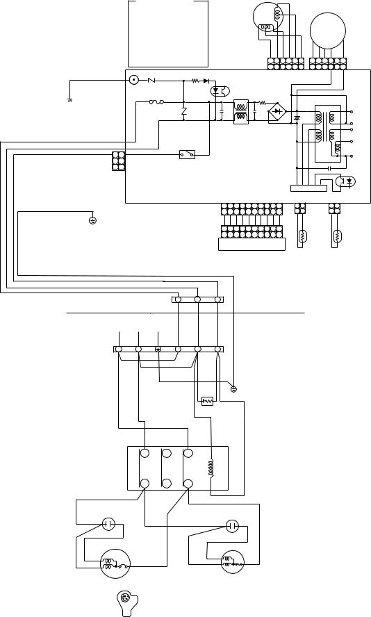
3-4. RAS-18UKP-ES3 / RAS-18UA-ES3, RAS-18UKP-AS3 / RAS-18UA-AS3
COLOR IDENTIFICATION
BRW : BROWN
RED : RED
WHI : WHITE
YEL : YELLOW
BLU : BLUE
BLK : BLACK
GRY : GRAY
PNK : PINK
ORN : ORANGE
GRN&YEL GREEN & YELLOW
GRN : GREEN
BLK |
R22 |
R09 |
P04 SG01 VARISTOR
DSA
T6.3A 250 V
F01 FUSE
R21
BLK |
CN30 |
WHI |
CN31 |
RED |
CN27 1 1 |
3 |
RY04 |
|
GRN&YEL
LOUVER |
|
|
|
|
|
FAN MOTOR |
|||||
|
|
|
|
|
|
|
|
||||
MOTOR |
|
|
|
|
|
DC MOTOR |
|
||||
|
|
|
|
|
|
|
|
|
|
||
|
|
|
|
|
BLU PNK YEL ORN RED BRW |
6 5 4 3 |
|
||||
|
|
|
|
|
|
6 5 4 |
3 |
2 1 |
1 |
||
|
|
|
|
|
|
6 5 4 |
3 2 1 |
6 5 4 3 |
1 |
||
|
|
|
|
|
|
CN 07 |
|
CN 10 |
|
||
IC04 |
|
|
|
|
|
|
|
|
|
|
|
|
L01 |
|
R01 |
DB01 |
|
T01 |
|
||||
|
|
|
|
|
|
|
|
|
|
||
C15 |
|
|
C01 |
|
|
+ |
|
|
DC15V |
||
|
|
|
|
|
|
|
|
C02 |
|
DC0V |
|
|
|
|
|
|
|
|
|
|
|
|
|
|
|
|
|
|
|
|
|
|
|
|
DC12V |
|
|
|
|
|
|
|
|
|
|
|
DC7V |
MAIN P.C. BOARD |
|
|
|
|
DC0V |
||||||
|
|
C06 |
|
|
|||||||
|
(MCC-821) |
|
|
|
|
||||||
|
|
|
|
|
IC02 |
||||||
|
|
|
|
|
|
|
|
|
|
|
|
|
|
|
|
|
|
|
|
|
IC |
|
|
|
2 3 |
CN13 |
|
|
|
|
CN03 IC01 |
CN01 |
|
||
1 |
4 |
5 6 |
7 |
8 |
9 10 |
|
1 2 |
|
1 2 |
|
|
1 |
2 3 |
4 |
5 6 |
7 |
8 |
9 10 |
|
1 2 |
|
1 2 |
|
BLU BLU BLU BLU BLU BLU BLU BLU BLU WHI |
BLK BLK |
BLK BLK |
HEAT |
||||||||
1 2 3 4 5 6 |
7 |
8 |
9 10 |
|
|
THERMO |
|
||||
1 |
2 3 |
4 |
5 6 |
7 |
8 |
9 10 CN25 |
SENSOR |
|
EXCHANGER |
||
INFRARED RAYS RECEIVE |
|
|
(TA) |
|
SENSOR |
||||||
|
|
|
|
(TC) |
|||||||
AND INDICATION PARTS |
|
|
|
|
|
||||||
|
|
INDOOR |
1 |
2 |
3 |
INDOOR |
|
|
|
TERMINAL |
|
|
|
UNIT |
|
|
|
BLOCK |
|
|
|
|
|
|
POWER SUPPLY |
|
|
|
|
OUTDOOR |
|
|
220 − 240 V ~ 50 Hz |
|
|
|
|
||
|
|
|
|
|
UNIT |
||
OUTDOOR |
L |
N |
|
1 |
2 |
3 |
|
TERMINAL |
|
GRN&YEL |
|||||
BLOCK |
|
|
|
|
BLK |
||
|
|
BLK |
|
|
|
||
|
|
|
|
|
|
|
|
|
|
RED |
|
|
BLK |
|
|
|
|
|
GRN&YEL |
|
|
||
|
|
|
|
|
|
||
BLK |
|
RED |
|
RED |
|
CHASSIS |
|
|
|
|
|
|
|
||
|
|
|
|
|
SPARK KILLER |
|
|
|
|
|
|
|
|
|
GRY |
|
|
R |
S |
T |
A1 |
(or A) |
|
|
|
|
|
|
|
||
MAGNETIC |
|
|
|
|
||
CONTACTOR |
|
|
A2 (or B) |
|
||
|
|
|
U |
V |
W |
|
CAPACITOR |
|
|
CAPACITOR |
|||
RED |
|
|
|
|
RED |
|
WHI |
S |
C |
|
|
WHI |
BLK |
|
BLK |
|
RED |
|||
PNK |
|
|
||||
|
|
|
|
|
||
|
R |
|
|
|
|
|
COMPRESSOR |
|
FAN MOTOR |
|
|||
|
|
|
||||
|
|
C |
|
|
|
|
|
|
R |
S |
|
|
|
COMPRESSOR TERMINAL
− 13 −
FILE NO. SVM-04007
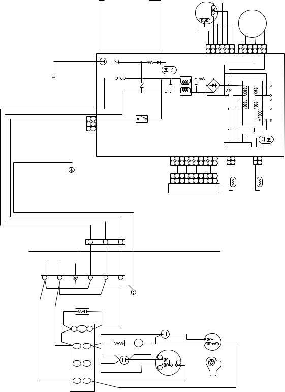
3-5.RAS-24UKP-AS3 / RAS-24UA-AS3
COLOR IDENTIFICATION
BRW : BROWN
RED : RED
WHI : WHITE
YEL : YELLOW
BLU : BLUE
BLK : BLACK
GRY : GRAY
PNK : PINK
ORN : ORANGE
GRN&YEL : GREEN & YELLOW
GRN : GREEN
BLK |
R22 |
R09 |
P04 SG01 VARISTOR
DSA
T6.3A 250 V
F01 FUSE
R21
BLK |
CN30 |
WHI |
CN31 |
RED |
CN27 1 1 |
3 |
RY04 |
|
GRN&YEL
LOUVER |
|
|
|
|
|
FAN MOTOR |
|||||||
|
|
|
|
|
|
|
|
|
|||||
MOTOR |
|
|
|
|
|
DC MOTOR |
|
||||||
|
|
|
|
|
|
|
|
|
|
|
|||
|
|
|
|
|
|
BLU PNK YEL ORN RED BRW |
6 5 4 |
|
|
||||
|
|
|
|
|
|
|
6 5 4 |
3 |
2 1 |
3 |
1 |
||
|
|
|
|
|
|
|
6 5 4 |
3 2 1 |
6 5 4 |
3 |
1 |
||
|
|
|
|
|
|
|
CN 07 |
|
CN 10 |
|
|
||
IC04 |
|
|
|
|
|
|
|
|
|
|
|
|
|
|
|
L01 |
|
R01 |
DB01 |
|
|
T01 |
|
||||
|
|
|
|
|
|
|
|
|
|
|
|
||
C15 |
|
|
|
C01 |
|
|
C02 |
|
|
DC15V |
|||
|
|
|
|
|
|
|
|
|
|
|
DC0V |
||
|
|
|
|
|
|
|
|
|
|
|
|
|
|
|
|
|
|
|
|
|
|
|
|
|
|
|
DC12V |
|
|
|
|
|
|
|
|
|
|
|
|
|
DC7V |
MAIN P.C. BOARD |
|
|
|
|
|
DC0V |
|||||||
|
|
C06 |
|
|
|||||||||
|
|
(MCC-821) |
|
|
|
|
|||||||
|
|
|
|
|
|
|
IC02 |
||||||
|
|
|
|
|
|
|
|
|
|
|
|
|
|
|
|
|
|
|
|
|
|
|
|
IC |
|
|
|
|
2 3 |
CN13 |
|
|
|
|
CN03 IC01 |
CN01 |
|
||||
1 |
4 |
5 6 |
7 |
8 |
9 10 |
|
1 2 |
|
|
1 2 |
|
||
1 |
2 3 |
4 |
5 6 |
7 |
8 |
9 10 |
|
1 2 |
|
|
1 2 |
|
|
BLU BLU BLU BLU BLU BLU BLU BLU BLU WHI |
BLK BLK |
|
BLK BLK |
|
|||||||||
1 |
2 |
3 |
4 |
5 6 |
7 |
8 |
9 10 |
|
|
|
|
|
|
1 |
2 3 |
4 |
5 6 |
7 |
8 |
9 10 CN25 |
THERMO |
|
HEAT |
||||
INFRARED RAYS RECEIVE |
|
|
SENSOR |
|
EXCHANGER |
||||||||
|
|
(TA) |
|
|
SENSOR |
||||||||
AND INDICATION PARTS |
|
|
|
|
|||||||||
|
|
|
|
|
(TC) |
||||||||
|
|
|
|
|
|
|
|
|
|
|
|
|
|
|
|
INDOOR |
1 |
2 |
3 |
|
|
|
|
|
|
|
TERMINAL |
|
|
INDOOR |
|
|
|||
|
|
BLOCK |
|
|
|
|
|
UNIT |
|
|
|
POWER SUPPLY |
|
|
|
|
|
OUTDOOR |
|
|
|
|
220 −240 V ~ 50 Hz |
|
|
|
|
|
|
|
||
|
|
|
|
|
|
UNIT |
|
|
||
|
|
|
|
|
|
|
|
|
|
|
OUTDOOR |
L |
N |
1 |
2 |
3 |
|
|
|
|
|
TERMINAL |
|
|
|
|
|
|||||
BLOCK |
BLK |
|
|
GRN&YEL |
|
|
|
|
|
|
|
|
|
|
|
|
|
|
|||
|
|
|
|
|
|
|
|
|
|
|
|
BLK |
RED |
|
|
|
|
|
|
|
|
|
|
|
|
|
CHASSIS |
|
|
|
|
|
|
|
RED |
|
|
|
|
|
|
|
|
|
|
|
|
|
|
|
|
|
|
|
|
|
BLK |
BLK |
|
GRY |
|
|
|
|
|
|
|
SPARK KILLER |
|
|
|
|
|
|
|
|
|
|
A1 52C A2 |
|
|
|
RED |
|
|
||
|
|
|
|
|
|
|
|
|
||
|
|
RED |
|
RED |
|
WHI |
WHI |
CAPACITOR |
WHI |
BLK |
|
|
R |
U |
|
RED |
|||||
|
|
|
ELECTRIC |
STARTING |
|
|
|
|||
|
|
|
|
|
|
FAN MOTOR |
||||
|
|
|
|
|
STARTER |
CAPACITOR |
S |
|||
|
|
|
|
RED |
|
|
WHI |
|
C |
|
|
|
S |
V |
|
|
|
PNK |
C BLK |
R |
S |
|
|
|
|
|
CAPACITOR |
|
R |
|
|
|
|
|
T |
W |
|
|
|
|
COMPRESSOR |
COMPRESSOR TERMINAL |
|
|
|
|
|
|
|
|
||||
MAGNETIC CONTACTOR
− 14 −

FILE NO. SVM-04007
4. SPECIFICATION OF ELECTRICAL PARTS
4-1. Indoor Unit (RAS-24UKHP-ES3, RAS-18UKHP-ES3, RAS-24UKHP-AS3, RAS-18UKHP-AS3)
No. |
Parts name |
Type |
|
Specifications |
1 |
Fan motor (for indoor) |
ICF-340-30-2 |
|
DC 340V, 30W |
|
|
|
|
|
2 |
Thermo sensor (TA-sensor) |
——— |
10k Ω at 25°C |
|
|
|
|
|
|
3 |
DC-DC transformer (T01) |
SWT-58A |
|
DC 390V, Secondary DC 15V, 12V, 7V |
|
|
|
|
|
4 |
Microcontroller |
TMP87CM40AN |
|
|
|
|
|
|
|
5 |
Heat exchanger sensor |
——— |
|
10kΩ at 25°C |
|
(TC-sensor) |
|
||
|
|
|
|
|
|
|
|
|
|
6 |
Line filter (L01) |
SS11V-R07190 |
|
19mH, AC 0.7A |
|
|
|
|
|
7 |
Diode (DB01) |
D3SBA60 |
|
4A, 600V |
|
|
|
|
|
8 |
Capacitor (C02) |
KMH450VNSN120M25C 120µF, 450V |
||
|
|
|
|
|
9 |
Fuse (F01) |
TSCR |
|
T6.3A, 250V |
|
|
|
|
|
10 |
Power supply IC (IC01) |
MA8920 |
|
5A, 900V |
|
|
|
|
|
11 |
Varistor (R21, R22) |
15G561K |
|
560V |
|
|
|
|
|
12 |
Resistor (R01) |
RF-5TK4R7B |
|
4.7Ω, 5W |
|
|
|
|
|
13 |
Louver motor |
MP35EA12 |
|
Output (Rated) 2W, 10poles, 4phase, |
|
|
|
|
DC 12V |
4-2. Outdoor Unit (RAS-24UAH-ES3, RAS-24UAH-AS3)
No. |
Parts name |
Type |
|
Specifications |
|
||
|
|
|
Output (Rated) 2200W, 2poles, 1 phase, 220 − 240V, 50Hz |
||||
1 |
Compressor |
PA290X3F-4MS |
Winding resistance (Ω |
) |
|
Red-Black |
White-Black |
|
|
|
(at 20°C) |
|
|
|
|
|
|
|
|
|
1.07 |
2.20 |
|
|
|
|
|
|
|
||
|
|
|
Output (Rated) 65W, 6poles, 1 phase, 220 – 240V, 50Hz |
||||
2 |
Fan motor (for outdoor) |
KFG6-71SB5P-T1 |
|
|
|
|
|
Winding resistance (Ω |
) |
|
Red-Black |
White-Black |
|||
|
|
|
(at 20°C) |
|
|
|
|
|
|
|
|
|
64.4 |
127.4 |
|
|
|
|
|
|
|
|
|
3 |
Running capacitor |
451355KQ |
AC 450V, 3.5µF |
|
|
|
|
(for fan motor) |
|
|
|
|
|||
|
|
|
|
|
|
|
|
4 |
Running capacitor |
371456JCR |
AC 370V, 45µF |
|
|
|
|
(for compressor) |
|
|
|
|
|||
|
|
|
|
|
|
|
|
|
|
|
|
|
|
|
|
5 |
Solenoid coil |
VHV (STF) |
AC 220 ~ 240V |
|
|
|
|
(for 4-way valve) |
|
|
|
|
|||
|
|
|
|
|
|
|
|
|
|
|
|
|
|
|
|
6 |
Thermo sensor |
TE / TD |
10kΩ at 25°C / 50kΩ |
at 25°C |
|
|
|
|
|
|
|
|
|
|
|
7 |
Magnetic contactor |
CLK-35J |
220 ~ 240V, 50Hz |
|
|
|
|
|
|
|
|
|
|
|
|
8 |
Transformer |
TT-05 |
220 ~ 240V |
|
|
|
|
|
|
|
|
|
|
|
|
9 |
Microcontroller |
TMP47C840N |
|
|
|
|
|
|
|
|
|
|
|
|
|
10 |
Varistor (R73, R74) |
15G471K |
470V |
|
|
|
|
|
|
|
|
|
|
|
|
11 |
Fuse (F01) |
TSCR |
T6.3A, 250V |
|
|
|
|
|
|
|
|
|
|
|
|
– 15 –
FILE NO. SVM-04007
4-3. Outdoor Unit (RAS-18UAH-ES3, RAS-18UAH-AS3)
No. |
Parts name |
Type |
|
Specifications |
|
||
|
|
|
Output (Rated) 1500W, 2poles, 1 phase, 220 − 240V, 50Hz |
||||
1 |
Compressor |
PA225X3F-4L |
|
|
|
|
|
Winding resistance (Ω |
) |
|
Red-Black |
White-Black |
|||
|
|
|
(at 20°C) |
|
|
|
|
|
|
|
|
|
1.35 |
2.68 |
|
|
|
|
|
|
|
||
|
|
|
Output (Rated) 65W, 6poles, 1 phase, 220 – 240V, 50Hz |
||||
|
|
|
|
|
|
|
|
2 |
Fan motor (for outdoor) |
HF-240-42B-2 |
Winding resistance (Ω |
) |
|
Red-Black |
White-Black |
|
|
|
(at 20°C) |
|
|
|
|
|
|
|
|
|
176.2 |
290.5 |
|
|
|
|
|
|
|
|
|
3 |
Running capacitor |
451205KQ |
AC 450V, 2 µF |
|
|
|
|
(for fan motor) |
|
|
|
|
|||
|
|
|
|
|
|
|
|
4 |
Running capacitor |
371456JCR |
AC 370V, 45µF |
|
|
|
|
(for compressor) |
|
|
|
|
|||
|
|
|
|
|
|
|
|
|
|
|
|
|
|
|
|
5 |
Solenoid coil |
VHV (STF) |
AC 220 − 240V |
|
|
|
|
(for 4-way valve) |
|
|
|
|
|||
|
|
|
|
|
|
|
|
|
|
|
|
|
|
|
|
6 |
Thermo sensor |
TE / TD |
10kΩ at 25°C / 50kΩ |
at 25°C |
|
|
|
|
|
|
|
|
|
|
|
7 |
Magnetic contactor |
CLK-26J |
220 − 240V, 50Hz |
|
|
|
|
|
|
|
|
|
|
|
|
8 |
Transformer |
TT-05 |
220 − 240V |
|
|
|
|
|
|
|
|
|
|
|
|
9 |
Microcomputer |
TMP47C840N |
|
|
|
|
|
|
|
|
|
|
|
|
|
10 |
Varistor (R73, R74) |
15G471K |
470V |
|
|
|
|
|
|
|
|
|
|
|
|
11 |
Fuse (F01) |
TSCR |
T6.3A, 250V |
|
|
|
|
|
|
|
|
|
|
|
|
4-4. Indoor Unit (RAS-24UKP-ES3, RAS-18UKP-ES3, RAS-24UKP-AS3, RAS-18UKP-AS3)
No. |
Parts name |
Type |
Specifications |
1 |
Fan motor (for indoor) |
ICF-340-30-2 |
DC 340V, 30W |
|
|
|
|
2 |
Thermo sensor (TA-sensor) |
——— |
10kΩ at 25°C |
|
|
|
|
3 |
DC-DC transformer (T01) |
SWT-58A |
DC 390V, Secondary DC 15V, 12V, 7V |
|
|
|
|
4 |
Microcontroller |
TMP87CM40AN |
|
|
|
|
|
5 |
Heat exchanger sensor |
——— |
10kΩ at 25°C |
|
(TC-sensor) |
||
|
|
|
|
6 |
Line filter (L01) |
SS11V-R07190 |
19mH, AC 0.7A |
|
|
|
|
7 |
Diode (DB01) |
D3SBA60 |
4A, 600V |
|
|
|
|
8 |
Capacitor (C02) |
KMH450VNSN120M25S |
1 20µF, 450V |
|
|
|
|
9 |
Fuse (F01) |
TSCR |
T6.3A, 250V |
|
|
|
|
10 |
Relay (for outdoor fan motor, |
AJQ1341 |
Coil DC 12V, 33mA, Rated 1A, AC 250V |
|
solenoid coil) (RY04) |
||
|
|
|
|
|
|
|
|
11 |
Power supply IC (IC01) |
MA8920 |
5A, 900V |
|
|
|
|
12 |
Varistor (R21, R22) |
15G561K |
560V |
|
|
|
|
13 |
Resistor (R01) |
RF-5TK4R7B |
4.7Ω, 5W |
|
|
|
|
14 |
Louver motor |
MP35EA12 |
Output (Rated) 2W,10poles, 4phase, |
|
|
|
DC 12V |
– 16 –
FILE NO. SVM-04007-(1)
4-5. Outdoor Unit (RAS-24UA-ES3, RAS-24UA-AS3)
No. |
Parts name |
Type |
Specifications |
|
|
|
|
|
Output (Rated) 2200W, 2poles, 1 phase, 220 − 240V, 50Hz |
||
|
|
|
|
|
|
1 |
Compressor |
5JS315DAB |
Winding resistance (Ω) |
Red-Black |
White-Black |
|
|
|
(at 20°C) |
|
|
|
|
|
0.83 |
2.257 |
|
|
|
|
|
|
|
|
|
|
Output (Rated) 65W, 6poles, 1 phase, 220 − 240V, 50Hz |
||
|
|
|
|
|
|
2 |
Fan motor (for outdoor) |
KFG6-71SB5P-T |
Winding resistance (Ω) |
Red-Black |
White-Black |
|
|
|
|
|
|
|
|
|
(at 20° C) |
64.4 |
127.4 |
|
|
|
|
|
|
3 |
Running capacitor |
451355KQ |
AC 450V, 3.5μF |
|
|
(for fan motor) |
|
|
|||
|
|
|
|
|
|
|
|
|
|
|
|
4 |
Running capacitor |
371456JCR |
AC 370V, 45μF |
|
|
(for compressor) |
|
|
|
|
|
|
|
|
|
|
|
5 |
Starting capacitor |
371456JCR |
AC 370V, 45μF |
|
|
|
(for compressor) |
|
|
|
|
|
(RAS-24UA-AS3) |
|
|
|
|
|
|
|
|
|
|
6 |
Magnetic contactor |
CLK-35J |
220 − 240V, 50Hz |
|
|
|
|
|
|
|
|
7 |
Electric starter |
ZPR0YCE101A500 |
AC 500V, 100Ω |
|
|
|
|
|
|
|
|
4-6. Outdoor Unit (RAS-18UA-ES3, RAS-18UA-AS3)
No. |
Parts name |
Type |
Specifications |
|
|
|
|
|
Output (Rated) 1500W, 2poles, 1 phase, 220 − 240V, 50Hz |
||
|
|
|
|
|
|
1 |
Compressor |
5KS225DAA |
Winding resistance (Ω) |
Red-Black |
White-Black |
|
|
|
|
|
|
|
|
|
(at 20°C ) |
1. 632 |
2.457 |
|
|
|
|
|
|
|
|
|
Output (Rated) 42W, 6poles, 1 phase, 220 − 240V, 50Hz |
||
2 |
Fan motor (for outdoor) |
HF-240-42B-1 |
|
|
|
Winding resistance (Ω) |
Red-Black |
White-Black |
|||
|
|
|
(at 20°C) |
|
|
|
|
|
176.2 |
290.5 |
|
|
|
|
|
|
|
3 |
Running capacitor |
451205KQ |
AC 450V, 2µF |
|
|
(for fan motor) |
|
|
|||
|
|
|
|
|
|
|
|
|
|
|
|
4 |
Running capacitor |
371456JCR |
AC 370V, 45μF |
|
|
(for compressor) |
|
|
|||
|
|
|
|
|
|
|
|
|
|
|
|
5 |
Magnetic contactor |
CLK-26J |
220 − 240V, 50Hz |
|
|
– 17 –
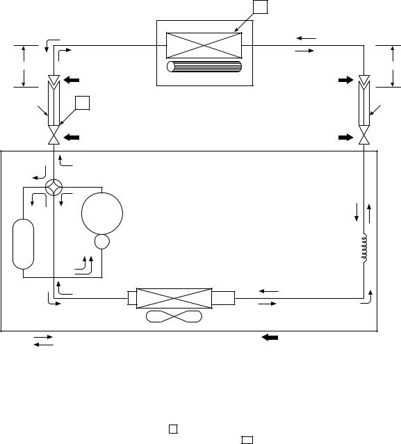
FILE NO. SVM-04007
5. REFRIGERATION CYCLE DIAGRAM
5-1. RAS-24UKHP-ES3 / RAS-24UAH-ES3 RAS-24UKHP-AS3 / RAS-24UAH-AS3
|
Cooling |
||
0.49m |
|
Heating |
|
(Connecting pipe) |
|||
|
|||
12.7 |
|
|
|
T1
Indoor unit
Heat exchanger |
Cross flow fan |
0.39m (Connecting pipe)6.35
O.D.:12.7mm |
P |
|
|
O.D.:6.35mm |
|
Packed valve |
|
|
Packed valve |
|
( 12.7) |
|
|
( 6.35) |
|
Gas container connection (Reinstall etc.) |
|
|
|
|
Heating |
|
|
|
Cooling |
4-way valve |
|
|
|
Heating |
Cooling Compressor |
PA290X3F-4MS |
|
|
Tank |
|
|
|
Capillary tube |
|
|
|
|
2.0x700s |
|
|
Condenser |
|
|
|
|
|
|
Refrigerant |
|
|
Propeller fan |
|
R410A 1.6 kg |
|
Cooling |
Outdoor unit |
Mark( |
)means check points of Gas Leak. |
|
Heating |
|
|
|
|
|
Standard |
Surface temp. of heat |
|
Ambient temp. |
||
|
|
Fan speed |
conditions DB/WB |
||||
|
50Hz |
pressure P |
exchanger interchanging |
(indoor) |
|
(°C) |
|
|
|
(MPaG) |
pipe T1 (°C) |
|
|
|
|
|
|
|
Indoor |
|
Outdoor |
||
|
|
|
|
|
|
||
|
|
|
|
|
|
|
|
|
Standard |
2.7 |
43.0 |
High |
20/– |
|
7/6 |
Heating |
|
|
|
|
|
|
|
Overload*1 |
3.1 ~ 4.0 |
52.0 ~ 59.0 |
Low |
27/– |
|
24/18 |
|
|
|
|
|
|
|
|
|
|
Low temperature |
2.7 |
36.0 |
High |
20/– |
|
–10/–10 |
|
|
|
|
|
|
|
|
|
Standard |
0.9 |
11.0 |
High |
27/19 |
|
35/24 |
Cooling |
|
|
|
|
|
|
|
Overload |
0.8 |
12.0 |
High |
32/23 |
|
43/26 |
|
|
|
|
|
|
|
|
|
|
Low temperature |
0.5 |
1.0 |
Low |
21/15 |
|
21/15 |
|
|
|
|
|
|
|
|
Note :
• Measure the heat exchanger temperature at the center of U-bend. (By means of TC sensor)
*1 • During heating overload operation, a value for the high temperature limit control operation is included.
– 18 –
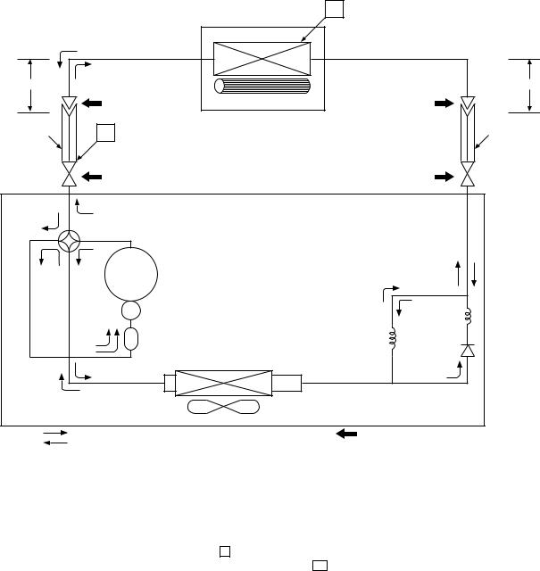
FILE NO. SVM-04007
5-2. RAS-18UKHP-ES3 / RAS-18UAH-ES3 RAS-18UKHP-AS3 / RAS-18UAH-AS3
|
Cooling |
||
0.39m |
|
Heating |
|
(Connecting pipe) |
|||
|
|||
12.7 |
|
|
|
T1
Indoor unit
Evaporator
Cross flow fan
0.49m (Connecting pipe)6.35
O.D.:12.7mm |
P |
|
|
|
O.D.:6.35mm |
|
Packed valve |
|
|
|
Packed valve |
|
( 12.7) |
|
|
|
( 6.35) |
|
Heating |
|
|
|
|
Cooling |
4-way valve |
|
|
|
|
Heating |
Cooling Compressor |
PA225X3F-4L |
|
|
|
|
|
|
|
|
Capillary tube |
|
|
|
Capillary tube |
1.0x1500s |
|
|
Accumulator |
|
|||
|
|
1.7x700s |
|
||
|
|
|
|
||
|
|
Condenser |
|
|
|
|
|
|
|
Refrigerant |
|
|
|
Propeller fan |
|
R410A 1.3 kg |
|
|
Cooling |
Outdoor unit |
Mark( |
)means check points of Gas Leak. |
|
|
Heating |
|
|
|
|
|
|
Standard |
Surface temp. of heat |
|
Ambient temp. |
||
|
50Hz |
Fan speed |
conditions DB/WB |
||||
|
pressure P |
exchanger interchanging |
(indoor) |
|
(°C) |
||
|
|
(MPaG) |
pipe T1 (°C) |
|
|
|
|
|
|
|
Indoor |
|
Outdoor |
||
|
|
|
|
|
|
||
|
|
|
|
|
|
|
|
|
Standard |
2.7 |
45.0 |
High |
20/– |
|
7/6 |
Heating |
|
|
|
|
|
|
|
Overload*1 |
3.0 ~ 3.8 |
49.0 ~ 58.0 |
Low |
27/– |
|
24/18 |
|
|
|
|
|
|
|
|
|
|
Low temperature |
2.0 |
34.0 |
High |
20/– |
|
–10/–10 |
|
|
|
|
|
|
|
|
|
Standard |
0.9 |
10.0 |
High |
27/19 |
|
35/24 |
Cooling |
|
|
|
|
|
|
|
Overload |
1.0 |
15.0 |
High |
32/23 |
|
43/26 |
|
|
|
|
|
|
|
|
|
|
Low temperature |
0.6 |
1.0 |
Low |
21/15 |
|
21/15 |
|
|
|
|
|
|
|
|
Note :
• Measure the heat exchanger temperature at the center of U-bend. (By means of TC sensor)
*1 • During heating overload operation, a value for the high temperature limit control operation is included.
– 19 –
FILE NO. SVM-04007
5-3. RAS-24UKP-ES3 / RAS-24UA-ES3 RAS-24UKP-AS3 / RAS-24UA-AS3
|
|
T1 |
|
|
Indoor unit |
|
Cooling |
Heat exchanger |
|
|
|
0.49m |
|
|
(Connecting pipe) |
|
|
|
12.7 |
Cross flow fan |
|
|
|
0.39m (Connecting pipe)6.35
O.D.:12.7mm |
|
P |
|
|
Packed valve |
||
|
|
( 12.7) |
|
|
|
||
|
|
||
|
|
Gas container connection (Reinstall etc.) |
|
O.D.:6.35mm
Packed valve ( 6.35) 
Cooling
Cooling Compressor 5JS315DAG01
Tank |
Capillary tube |
||
|
2.0x700s |
||
|
|||
Condenser
|
|
|
|
Refrigerant |
|
Propeller fan |
|
|
R410A 1.6kg |
Cooling |
Outdoor unit |
Mark( |
|
)means check points of Gas Leak. |
|
||||
|
|
|
Standard |
Surface temp. of heat |
|
Ambient temp. |
||
|
|
Fan speed |
conditions DB/WB |
||||
|
50Hz |
pressure P |
exchanger interchanging |
(indoor) |
|
(°C) |
|
|
|
(MPaG) |
pipe T1 (°C) |
|
|
|
|
|
|
|
Indoor |
|
Outdoor |
||
|
|
|
|
|
|
||
|
|
|
|
|
|
|
|
|
Standard |
0.9 |
6.0 |
High |
27/19 |
|
35/24 |
Cooling |
|
|
|
|
|
|
|
Overload |
0.8 |
10.0 |
High |
32/23 |
|
43/26 |
|
|
|
|
|
|
|
|
|
|
Low temperature |
0.6 |
2.0 |
Low |
21/15 |
|
21/15 |
|
|
|
|
|
|
|
|
Note :
• Measure the heat exchanger temperature at the center of U-bend. (By means of TC sensor)
– 20 –
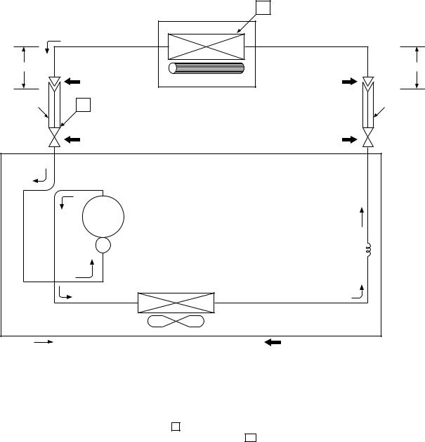
FILE NO. SVM-04007
5-4. RAS-18UKP-ES3 / RAS-18UA-ES3 RAS-18UKP-AS3 / RAS-18UA-AS3
|
|
T1 |
|
|
Indoor unit |
|
Cooling |
Evaporator |
|
|
|
0.39m |
|
|
(Connecting pipe) |
|
|
|
12.7 |
Cross flow fan |
|
|
|
0.49m (Connecting pipe)6.35
O.D.:12.7mm |
P |
|
|
O.D.:6.35mm |
|
Packed valve |
|
|
Packed valve |
|
( 12.7) |
|
|
( 6.35) |
Cooling |
|
|
|
|
|
Cooling Compressor |
5KS225DAA |
|
|
|
|
|
|
Capillary tube |
|
|
|
|
1.7x600s |
|
|
Condenser |
|
|
|
|
|
|
Refrigerant |
|
|
Propeller fan |
|
R410A 1.14 kg |
|
Cooling |
Outdoor unit |
Mark( |
)means check points of Gas Leak. |
|
|
Standard |
Surface temp. of heat |
|
Ambient temp. |
||
|
50Hz |
Fan speed |
conditions DB/WB |
||||
|
pressure P |
exchanger interchanging |
(indoor) |
|
(°C) |
||
|
|
(MPaG) |
pipe T1 (°C) |
|
|
|
|
|
|
|
Indoor |
|
Outdoor |
||
|
|
|
|
|
|
||
|
|
|
|
|
|
|
|
|
Standard |
0.9 |
10.0 |
High |
27/19 |
|
35/24 |
Cooling |
|
|
|
|
|
|
|
Overload |
1.0 |
13.0 |
High |
32/23 |
|
43/26 |
|
|
|
|
|
|
|
|
|
|
Low temperature |
0.6 |
2.0 |
Low |
21/15 |
|
21/15 |
|
|
|
|
|
|
|
|
Note :
• Measure the heat exchanger temperature at the center of U-bend. (By means of TC sensor)
– 21 –
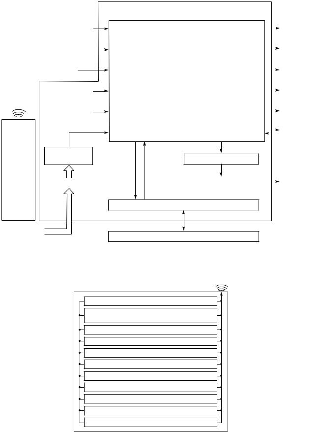
FILE NO. SVM-04007
6. CONTROL BLOCK DIAGRAM
6-1. RAS-24UKHP-ES3, RAS-18UKHP-ES3 / RAS-24UKHP-AS3, RAS-18UKHP-AS3
Indoor Unit Control Panel
|
|
|
|
|
|
|
M.C.U. |
|
|
|
|||
|
|
|
|
|
|
|
Functions |
|
|
Operation |
|||
|
Heat Exchanger Sensor |
|
|
|
|||||||||
|
|
∙ Louver Control |
|
|
Display |
||||||||
|
|
|
|||||||||||
|
|
|
|
|
|
|
|
|
|||||
|
|
|
|
|
|
|
|
|
|
|
|
|
|
|
|
|
|
|
|
|
|
|
|
|
|
|
|
|
|
|
|
|
|
|
|
|
|
|
|
|
Timer |
|
|
Temperature Sensor |
|
|
∙ 3-minute Delay at Restart for Compressor |
|
|
|
|||||
|
|
|
|
|
|
|
Display |
||||||
|
|
|
|
|
|
||||||||
|
|
|
|
|
|
|
|
|
|
|
|
|
|
|
|
|
|
|
|
|
|
|
|
|
|
|
|
|
|
|
|
|
|
|
|
|
|
|
|
|
Filter Sign |
Infrared Rays Signal Receiver |
|
|
|
∙ Motor Revolution Control |
|
|
|
|
|||||
|
|
|
|
|
|
Display |
|||||||
|
|
|
|
|
|
|
|
|
|
|
|
|
|
|
|
|
|
|
|
|
∙ 20 sec Self Cleaning Function |
|
|
|
|||
|
|
|
|
|
|
|
|
|
|||||
|
|
|
|
|
|
|
|
|
PRE DEF. |
||||
|
|
|
|
|
|
|
|
|
|
|
|
|
|
|
|
|
Initiallizing Circuit |
|
∙ Processing |
|
|
|
|||||
|
|
|
|
|
|
|
Sign Display |
||||||
|
Infrared |
|
|
|
|
(Temperature Processing) |
|
|
|||||
|
|
|
|
|
|
|
|
||||||
|
|
|
|
|
|
|
|
||||||
|
Rays |
|
|
|
|
|
|
|
|
|
|
|
|
|
Clock Frequency |
|
∙ Timer |
|
|
|
|
|
Hi Power |
||||
|
|
|
|
|
|
|
|
|
|||||
|
|
|
Oscillator Circuit |
|
|
|
|
Sign Display |
|||||
|
|
|
|
|
|
|
|
|
|
|
|
|
|
|
|
|
|
|
|
|
|
|
|
|
|
|
|
|
|
|
|
|
|
|
∙ Serial Signal Communication |
|
|
|
|
|
Indoor |
|
|
|
|
|
|
|
|
|
|
|
|
Fan Motor |
|
|
|
|
|
|
|
|
|
|
|
|
|||
|
|
|
|
|
|
|
|
|
|
|
|
|
|
Power Supply
Circuit Louver ON/OFF Signal
Remote
Control
|
|
|
|
|
|
Noise Filter |
|
Louver Driver |
|
|
Louver Motor |
|
|||||
|
|
|
|
|
|
|
|
|
|
|
|
Serial Signal Transmitter/Receiver
From Outdoor Unit |
|
220 ~ 240V AC 50Hz |
Serial Signal Communication |
REMOTE CONTROL
Infrared Rays
Remote Control
Operation (START/STOP)
Operation Mode Selection
AUTO, COOL, DRY, HEAT, FAN ONLY
Temperature Setting
Fan Speed Selection
ON TIMER Setting
OFF TIMER Setting
Louver Auto Swing
Louver Direction Setting
ECO
Hi power
Filter Reset
– 22 –

FILE NO. SVM-04007
6-2. RAS-24UKP-ES3, RAS-18UKP-ES3 / RAS-24UKP-AS3, RAS-18UKP-AS3
Indoor Unit Control Panel
|
|
|
|
|
|
|
|
|
|
|
M.C.U. |
|
|
|
||
|
|
|
|
|
|
|
|
|
|
|
|
|
|
|
|
|
|
|
|
|
|
|
|
Functions |
|
|
|
|
|
|
Operation |
||
|
|
Heat Exchanger Sensor |
|
|
|
|
|
|
|
|
||||||
|
|
|
|
Louver Control |
|
|
|
|
|
|
Display |
|||||
|
|
|
|
|
|
|
|
|
|
|
|
|
||||
|
|
|
|
|
|
|
|
|
|
|
|
|
|
|||
|
|
|
|
|
|
|
|
|
|
|
|
|
|
|
|
|
|
|
|
|
|
|
|
|
|
|
|
|
|
|
|
|
Timer |
|
|
Temperature Sensor |
|
|
3-minute Delay at Restart for Compressor |
|
|
|||||||||
|
|
|
|
|
|
Display |
||||||||||
|
|
|
|
|||||||||||||
|
|
|
|
|
|
|
|
|
|
|
|
|
|
|
|
|
|
|
|
|
|
|
|
|
|
|
|
|
|
|
|
|
|
|
|
|
|
|
|
|
|
|
|
|
|
|
|
|
|
|
|
|
|
|
|
|
|
|
|
|
|
|
|
|
|
|
Filter Sign |
|
Infrared Rays Signal Receiver |
|
|
|
|
Motor Revolution Control |
|
|
||||||||
|
|
|
|
|
|
Display |
||||||||||
|
|
|
|
|
|
|
|
|
|
|
|
|
|
|
|
|
|
|
|
|
|
|
|
|
20 sec Self Cleaning function |
|
|
|
|||||
|
|
|
|
|
|
|
|
|
|
|
||||||
|
|
|
|
|
|
|
|
|
|
|
|
|
|
|
|
Fan Only |
|
|
|
Initiallizing Circuit |
|
|
|
Processing |
|
|
|
|
|||||
|
|
Infrared |
|
|
|
|
|
|
|
|
Sign Display |
|||||
|
|
|
|
|
|
|
(Temperature Processing) |
|
|
|||||||
|
|
|
|
|
|
|
|
|
|
|||||||
|
|
Rays |
|
|
|
|
|
|
|
|
|
|
|
|
|
|
Clock Frequency |
|
|
Timer |
|
|
|
|
|
|
Hi Power |
||||||
|
|
|
|
|
|
|
|
|
|
|
||||||
|
|
|
Oscillator Circuit |
|
|
|
|
|
|
|
|
Sign Display |
||||
|
|
|
|
|
|
|
|
|
|
|
|
|
|
|||
|
|
|
|
|
|
|
|
|
|
|
|
|
|
|
|
|
|
|
|
|
|
|
|
|
|
|
|
|
|
|
|
|
|
|
|
|
|
|
|
|
|
|
|
|
|
|
|
|
|
Indoor |
|
|
|
|
|
|
|
|
|
|
|
|
|
|
|
|
Fan Motor |
|
|
|
|
|
|
|
|
|
|
|
|
|
|
|
|
|
|
|
|
|
|
|
|
|
|
|
|
|
|
|
|
|
|
|
|
|
Power Supply |
|
|
|
|
|
|
|
|
|
|
|
|
|
|
|
|
|
|
|
|
|
|
|
|
|
|
|
|
||
|
|
Remote |
Circuit |
|
|
|
Outdoor unit |
|
|
Louver ON/OFF Signal |
|
|
|
|||
|
|
|
|
|
|
|
ON/OFF Signal |
|
|
|
|
|
|
|
||
|
|
Control |
|
|
|
|
|
|
|
|
|
|
|
|
|
|
|
|
|
|
|
|
|
|
|
|
|
|
|
|
|
|
|
|
|
|
Noise Filter |
|
|
|
Relay Driver |
|
|
Louver Driver |
|
|
Louver Motor |
|||
|
|
|
|
|
|
|
|
|
|
|
|
|
|
|
||
|
|
|
|
|
|
|
|
|
|
|
|
|
|
|
|
|
|
|
|
|
|
|
|
|
|
|
|
|
|
|
|
|
|
|
|
|
|
|
|
|
|
|
|
|
|
|
|
|
|
|
|
|
|
|
|
|
|
|
|
|
|
|
|
|
|
|
|
|
|
|
|
|
|
|
|
|
|
Relay RY04 |
|
|
|
|||
From Outdoor Unit |
|
|
|
|
|
|
|
|
|
|
|
|
|
|
||
|
|
|
|
|
|
|
|
|
|
|
|
|
|
|||
220 ~ 240V AC 50Hz |
|
|
|
|
|
|
|
Outdoor Unit |
|
|
|
|||||
|
|
|
|
|
|
|
|
|
|
|
|
|
|
|
|
|
REMOTE CONTROL
Infrared Rays
Remote Control
Operation (START/STOP)
Operation Mode Selection
AUTO, COOL, DRY, FAN ONLY
Temperature Setting
Fan Speed Selection
ON TIMER Setting
OFF TIMER Setting
Louver Auto Swing
Louver Direction Setting
ECO
Hi power
Filter Reset
− 23 −
FILE NO. SVM-04007
7. OPERATION DESCRIPTION
7-1. Outline of Air Conditioner Control
This is a fixed capacity type air conditioner, which uses a DC motor for an indoor fan. The DC motor drive circuit is mounted in the indoor unit. And electrical parts which operate the compressor and the outdoor fan motor, are mounted in the outdoor unit.
The air conditioner is mainly controlled by the indoor unit controller. The controller operates the indoor fan motor based upon commands transmitted by the remote control and transfers the operation commands to the outdoor unit controller.
The outdoor unit controller receives operation commands from the indoor unit, and operates the outdoor fan motor and the compressor.
(1)Role of indoor unit controller
The indoor unit controller receives the operation commands from the remote control and executes them.
∙Temperature measurement at the air inlet of the indoor heat exchanger by the indoor temperature sensor
∙Temperature setting of the indoor heat
exchanger by the heat exchanger sensor
∙Louver motor control
∙Indoor fan motor operation control
∙LED display control
∙Transferring of operation commands to the outdoor unit
∙Receiving of information of the operation status and judging of the information or indication of error
(2)Role of outdoor unit controller
The outdoor unit controller receives the operation commands from the indoor controller and executes them.
∙ Compressor operation control
· Operation control of outdoor fan motorf
·Turning off the compressor and outdoor fan when the outdoor unit receives the shutdown command
·Defrost control in heating operation (Temperature measurement by the outdoor heat exchanger and control for the four-way valve and the outdoor fan motor) *Heat pump Model only
7-1-1. Louver control
(1)Vertical air flow louver
Position of veritcal air flow louver is automatically controlled according to the operation mode. Besides, position of vertical air flow louver can be arbitrarily set by pressing [FIX] button.
The louver position which is set by [FIX] button is stored in the microcomputer, and the louver is automatically set at the stored position for the next operation.
(2)Swing
If [SWING] button is pressed when the indoor unit is in operation, the vertical air flow louver starts swinging. When [FIX] button is pressed, it stops swinging.
7-1-2. Indoor fan control (DC Fan motor)
(1)The indoor fan is operated by the stepless speed change DC motor.
(2)For air flow level, speed of the indoor fan motor is controlled in five steps (LOW, LOW+, MED, MED+ and HIGH). If AUTO mode is selected, the fan motor speed is automatically controlled by the difference between the preset temperature and the room temperature.
Table 7-1-1
|
|
|
RAS-24UKHP-ES3 RAS-18UKHP-ES3 |
|||||
MODEL |
RAS-24UKHP-AS3 RAS-18UKHP-AS3 |
|||||||
|
|
|
|
|
||||
Motor speed |
Air flow level Motor speed |
Air flow level |
||||||
|
|
|
||||||
|
|
|
(rpm) |
(m3/h) |
(rpm) |
(m3/h) |
||
Cooling |
HIGH |
1350 |
950 |
1150 |
750 |
|
||
and |
|
MED |
1150 |
750 |
1050 |
650 |
|
|
Fan only |
|
LOW |
1000 |
600 |
900 |
530 |
|
|
|
|
HIGH |
1350 |
950 |
1200 |
800 |
|
|
Heating |
|
MED |
1200 |
800 |
1100 |
700 |
|
|
|
|
LOW |
1050 |
650 |
950 |
570 |
|
|
|
|
|
|
|
|
|
|
|
MODEL |
RAS-24UKP-ES3 RAS-18UKP-ES3 |
||||||
RAS-24UKP-AS3 |
RAS-18UKP-AS3 |
||||||
|
|
|
|||||
Cooling |
HIGH |
1350 |
950 |
1150 |
750 |
||
and |
|
MED |
1150 |
750 |
1050 |
650 |
|
Fan only |
|
LOW |
1000 |
600 |
900 |
530 |
|
|
|
|
|
|
|
|
|
LOW+ = LOW+MED 2
MED+ = MED+HIGH 2
– 24–
Loading...