


IK-CU44A
INSTRUCTION MANUAL
CAMERA CONTROL UNIT
IK-CU44A
For Customer Use
Enter below the Serial No.
which is located on the
bottom of the cabinet. Retain this information for future reference.
Model No.: IK-CU44A
Serial No.:
INFORMATION
This equipment has been tested and found to comply with the limits for a Class A digital device,
pursuant to Part 15 of the FCC Rules. These limits are designed to provide reasonable protection
against harmful interference when the equipment is operated in a commercial environment. This
equipment generates, uses, and can radiate radio frequency energy and, if not installed and used
in accordance with the instruction manual, may cause harmful interference to radio communications. Operation of this equipment in a residential area is likely to cause harmful interference in
which case the user will be required to correct the interference at his own expense.
USER-INSTALLER CAUTION: Your authority to operate this FCC verified equipment could be
voided if you make changes or modifications not expressly approved by the party responsible for
compliance to Part 15 of the FCC rules.
This Class A digital apparatus meets all requirements of the Canadian Interference Causing Equipment Regulations.
Cet appareil numérique de la classe A respecte toutes les exigences du Règlement sur le matériel
brouilleur du Canada.
1
SAFETY PRECAUTIONS
Read the following safety precautions carefully before using this product. These instructions
contain valuable information on safe and proper use that will prevent harm and damage to
the operator and other persons. Make sure that you fully understand the following details
(indications, graphic symbols) before proceeding to the remaining sections in this manual.
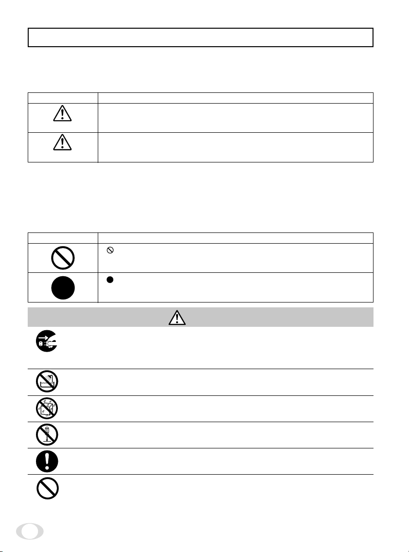
Indication definitions
Indication
This indicates the existence of a hazard that death or catastrophic
Warning
Caution
*1: Catastrophic bodily injury means loss of eyesight, burns (high and low temperatured),
shock, fracture, poisoning, etc. which leaves a sequela and require hospitalization or prolonged treatment.
*2: Bodily injury means injuries, burns and electric shock which does not require hospitaliza-
tion or prolonged treatment.
*3: Property damage means extended harm to home, household effects, domesticated ani-
mals, and pets.
bodily injury*1 may result from improper use.
This indicates the existence of a hazard that bodily injury*2 or property
damage*3 may result from improper use.
Meaning
Graphic symbol definitions
Symbol
" "indicates a prohibited action that must not be carried out. The actual
prohibited action is indicated in the symbol or nearby graphically or
described in text.
" "indicates a mandatory action that must be carried out. The actual
instruction is indicated in the symbol or nearby graphically or described
in text.
Meaning
Warning
• Stop operation immediately when any abnormality or defect occurs.
Use during an abnormal condition; such as emitting smoke, burning odors, damage from dropping invasion of foreign objects, etc. may cause fire and/or electric
shock. Be always sure to disconnect the power plug from the electrical outlet
(socket) at once and contact your dealer.
• Avoid installing in a shower room or a bathroom.
This may cause fire and/or electric shock.
• Do not operate in places with possibility of becoming wet.
This may cause fire and/or electric shock.
• Do not repair, disassemble and/or modify by yourself.
This may cause fire and/or electric shock. Be always sure to contact your dealer
for internal repair, check and cleaning of the product.
• Use the specified power supply.
Otherwise, a fire or an electric shock may occur.
• Don't place things or materials on the unit.
Ingress of foreign materials such as metallic things and liquid into the unit may
cause a fire or an electric shock.
2
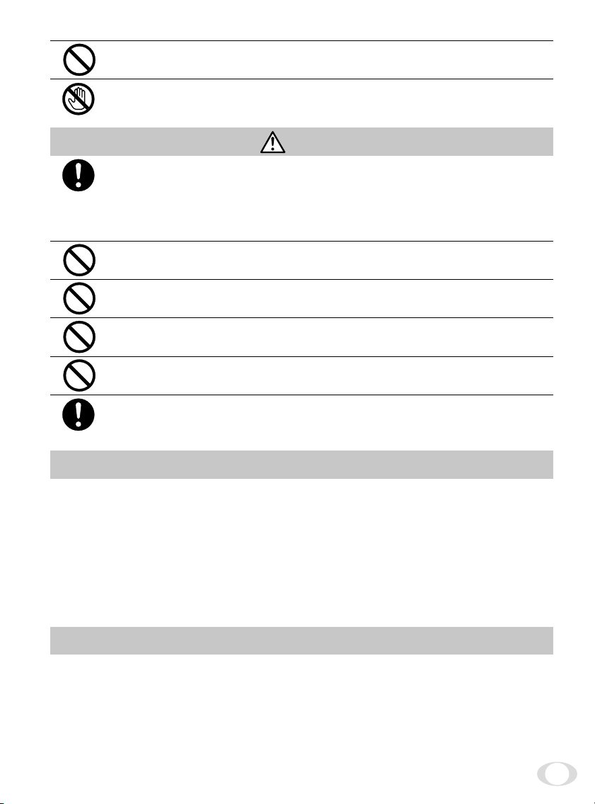
• Do not put the product in an unstable, slanting and/or vibrated place.
Drop and/or fail of the product may cause injury.
•
Do not touch the power cord or other connection cables during a thunderstorm.
This might cause electric shock.
Caution
• Note the following instructions when installing.
• Do not put an inflammable material on the product.
• Do not put the product on an Inflammable material such as carpet or blanket.
• Do not block a vent hole.
• Do not put the product in a narrow space, since the heat generated from the
product may be difficult to emanate.
If you do not follow the above, the heat generated by the product may cause fire.
• Do not put the product in direct sunshine and/or high temperature.
The temperature inside the product may cause fire.
• Avoid setting in humid, smoky, vaporized or dusty places. A fire or an
electric shock may occur in such places.
This may cause fire and/or electric shock.
• Do not point the lens directly at the sun and/or intensive light such as
direct sunlight, etc.
Focusing of the light may cause injury of eye and/or fire.
• Do not put the product in your mouth or swallow any parts.
This may cause suffocation and/or injury.
• Ask your dealer to perform a periodical check and internal cleaning
(approx. once every five years).
Dust inside the product may cause fire and/or trouble. For check and cleaning
cost, please consult your dealer.
Disclaimer
We disclaim any responsibility and shall be held harmless for any damages or losses incurred
by the user in any of the following cases:
1. Fire, earthquake or any other act of God; acts by third parties; misuse by the user, whether
intentional or accidental; use under extreme operating conditions.
2. Malfunction or non-function resulting in indirect, additional or consequential damages,
including but not limited to loss of expected income and suspension of business activities.
3. Incorrect use not in compliance with instructions in this instruction manual.
4. Malfunctions resulting from misconnection to other equipment.
5. Repairs or modifications made by the user or caused to be made by the user and carried
out by an unauthorized third party.
6. Notwithstanding the foregoing, Toshiba’s liabilities shall not, in any circumstances, exceed
the purchase price of the product.
Copyright and Right of Portrait
There may be a conflict with the Copyright Law and other laws when a customer uses, displays, distributes, or exhibits an image picked up by a television camera without permission
from the copyright holder. Please also note that transfer of an image or file covered by copyright is restricted to use within the scope permitted by the Copyright Law.
3

TABLE OF CONTENTS
SAFETY PRECAUTIONS ................................................................................. 2
1. COMPONENTS............................................................................................... 5
2. SPECIFICATIONS ........................................................................................... 5
3. NAMES AND FUNCTIONS ............................................................................ 6
4. CONNECTION ................................................................................................ 8
4.1 An Example of Standard Connection ................................................... 8
4.2 Cautions on Connection ......................................................................... 8
4.3 Connection on Back Panel ..................................................................... 9
4.4 Connector Pin Assignments .................................................................. 9
5. WHEN USING THE CAMERA WITH THE CAMERA UNIT FIXED ............. 10
6. OPERATION .................................................................................................. 11
6.1 AGC (Automatic Gain Control) ............................................................ 11
6.2 White Balance ....................................................................................... 11
(1) White balance adjustment in modes other than AUTO ................... 12
(1.1) White balance adjustment in SET mode ...................................... 12
(1.2) White balance adjustment in MANU mode ................................. 12
6.3 FUNC LOCK Switch .............................................................................. 12
7. MODE SETTING BY ON SCREEN DISPLAY .............................................. 13
7.1 FILE (Scene File) .................................................................................... 14
7.2 SHUTTER (Electronic Shutter, Backlight Correction) ........................ 14
(1) Detail setting in AUTO mode (auto electronic shutter) .................... 15
(2) SS (synchronized scan) ........................................................................ 15
7.3 Pedestal ................................................................................................. 16
7.4 SYNC (Setting for External Synchronization) ................................... 16
7.5 AREA (Measurement Area) .................................................................. 17
(1) Setting AREA the same for AGC,
auto electronic shutter and white balance ......................................... 17
(2) Setting AREA separately for AGC,
auto electronic shutter and white balance ......................................... 18
7.6 WB-OFFSET (White Balance Offset) ................................................... 19
7.7 INIT. (Scene File Initialization) ............................................................. 20
7.8 END (Ending ON SCREEN DISPLAY) .................................................. 20
8 EXTERNAL SYNC ........................................................................................ 21
9. CAUTIONS ON USE AND INSTALLATION ................................................ 22
10. BEFORE MAKING A SERVICE CALL .......................................................... 23
11. OPTIONAL PARTS........................................................................................ 23
12. EXTERIOR DIMENSIONS ............................................................................ 24
Servicing Instructions for Service Personnel
13. Connection to camera Head (IK-M43/IK-C43H) ........................................ 25
4
1. COMPONENTS
(1) Camera control unit .................................................................................. 1
(2) Accessories
(a) Instruction manual............................................................................. 1
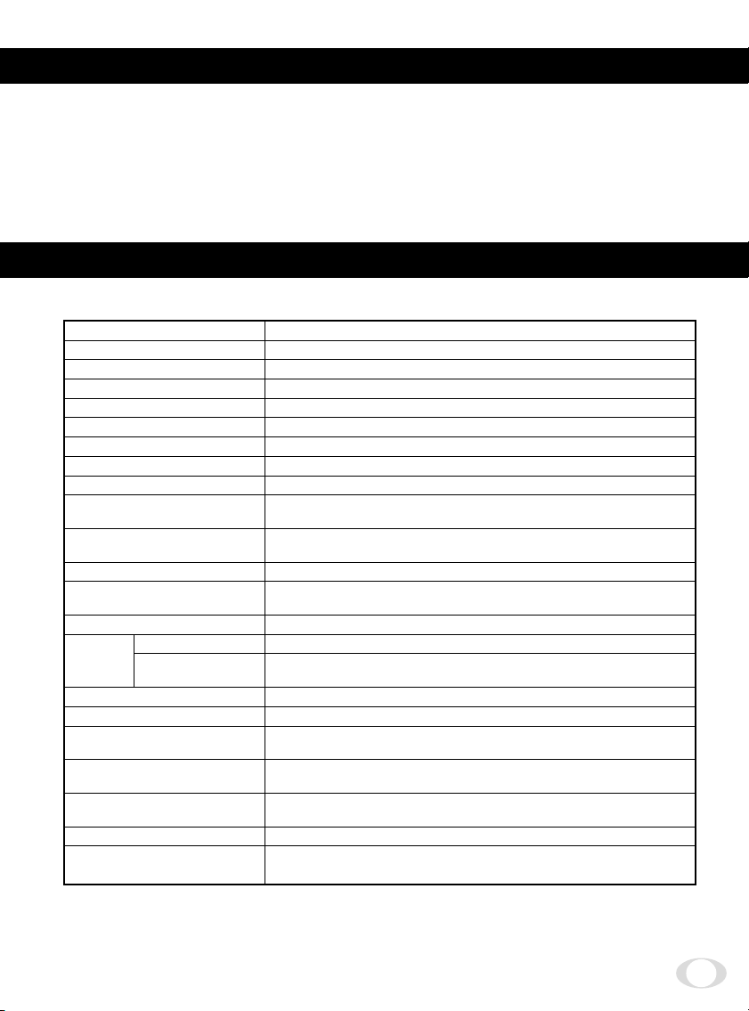
2. SPECIFICATIONS
Specification with camera head (IK-M44H) connected.
Power supply DC12V ± 0.5V
Power consumption 310 mA
Image sensor 1/2 inch IT-CCD
Effective pixels Horizontal: 768 pixels, Vertical: 494 pixels
Effective image area Horizontal: 6.54 mm, Vertical: 4.89 mm (1/2 inch type)
Scanning system 2:1 interlace
Scan frequency Horizontal: 15.734 kHz, Vertical: 59.94 Hz
Sync system Internal/External (automatic switching)
Resolution Horizontal: More than 470 lines, Vertical: More than 350 lines
Standard intensity of
illumination for objects
Minimum intensity of
illumination for objects
S/N ratio 46 dB or more
Video output
Output impedance 75Ω unbalanced
External
sync
White balance Automatic/set/manual
Gain switch (AGC) SENS UP (+6 dB)/ON/OFF
Electronic shutter
Operating temperature/
humidity
Anti-vibration/
shock characteristics
Weight Control unit: 0.86 lbs (390g)
Dimensions Control unit: W: 3.35”, H: 1.57”, D: 6.14”
(Without protrusion) (W: 85 mm, H: 40 mm, D: 156 mm)
Input VBS 1.0 V(p-p) (BNC terminal) NTSC 75Ω unbalanced
Adjustment
function
30 lx (F1.6, 3000K)
2.5 lx (F1.6, 3000K)
VBS 1.0 V(p-p), (BNC terminal) NTSC system
Y/C separation output (S terminal)
Subcarrier phase, H phase
Automatic, 1/60s, 1/100s, 1/250s, 1/500s, 1/1000s, 1/2000s,
1/4000s, 1/10000s, synchronized scan
14°F to 104°F (–10°C to +40°C)/Less than 90%
70 m/s2 (10 to 200 Hz)/700 m/s
2
Design and specifications are subject to change without notice.
5
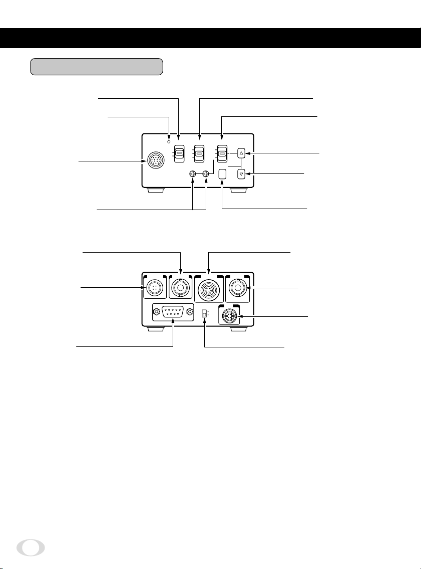
3. NAMES AND FUNCTIONS
Camera Control Unit
POWER switch
2
POWER indicator
3
CAMERA
1
terminal
White balance
6
adjust control
EXT SYNC
q
terminal
DC IN 12V
p
terminal
REMOTE
r
terminal
CAMERA POWER AGC WB
ON
OFF
DC IN 12V EXT SYNC
REMOTE
UP
ON
OFF
RB
FUNC LOCK
AUTO
SET
MANU
S-VIDEO VIDEO
ON
OFF
FUNC
AGC switch
4
WB switch
5
WB
SET
w
e
IRIS
FUNC LOCK switch
t
UP button
8
DOWN button
9
FUNC button
7
S-VIDEO terminal
VIDEO terminal
IRIS terminal
y
6

CAMERA terminal Connects to the camera head.
1
POWER switch Turns on and off the camera control unit.
2
POWER indicator Lights up when the power is turned on.
3
AGC switch Selects the gain mode. (AGC OFF/AGC ON/SENS UP)
4
WB switch Selects the white balance mode. (MANU/SET/AUTO)
5
White balance adjust control Adjusts the R gain and B gain with the white balance
6
FUNC button Determines the setting indication contents when the set-
7
UP button Selects the setting item when the setting menu is dis-
8
DOWN button Selects the setting item when the setting menu is dis-
9
DC IN 12V terminal Accepts a DC power supply (12V).
p
EXT SYNC terminal Accepts an external sync signal to synchronize the cam-
q
S-VIDEO terminal Connects terminal to S input terminal of a monitor or a
w
VIDEO terminal Connects terminal to video input terminal of a monitor
e
REMOTE terminal Controls the functions via RS232C.
r
FUNC LOCK switch Locks the switches and control on the front panel. When
t
IRIS terminal Connect when using an automatic iris lens.
y
mode set to MANU by the WB switch 5.
ting menu is displayed on the screen.
played on the screen. (When the WB switch 5 is set to
SET, pressing the UP button for more than 2 sec. activates the white balance SET operation.)
played on the screen.
era output signal with external signal.
VCR, etc.
Can be used at the same time as video terminal.
or a VCR, etc.
Can be used at the same time with the S-VIDEO termi-
nal.
the FUNC LOCK switch is set to ON, all settings except
for the POWER switch 2 and the file item of the screen
setting menu are locked out.
7
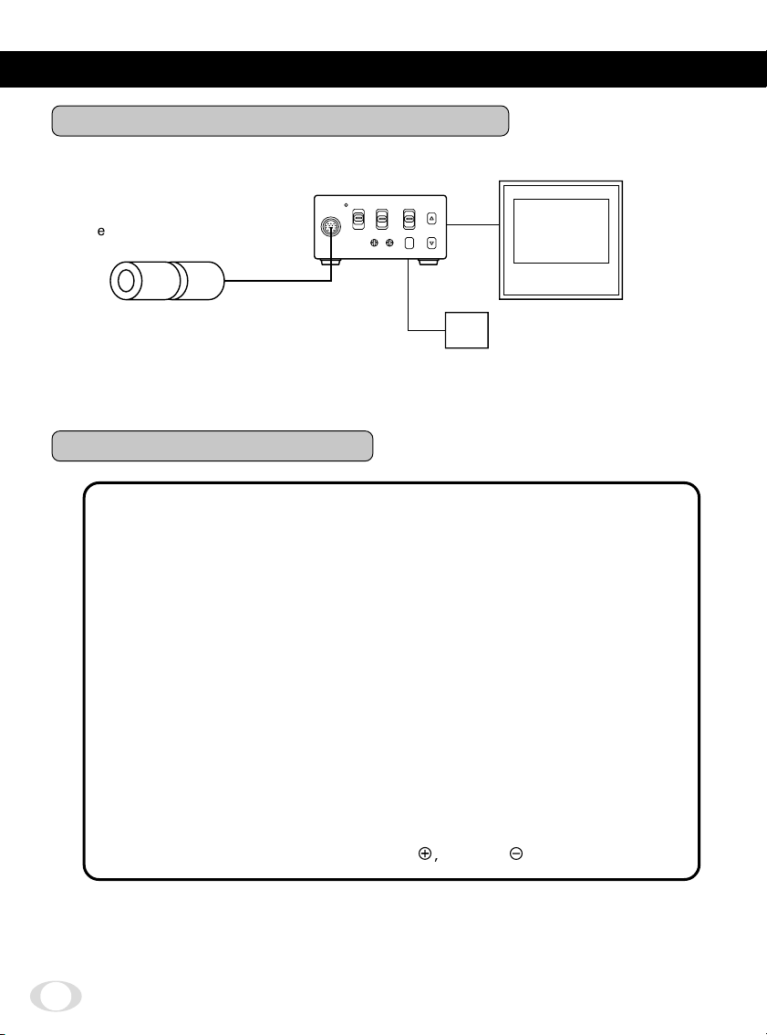
4. CONNECTION
4.1 An Example of Standard Connection
Monitor
Lens
(Option)
Camera
head (Option)
Camera cable
(Option)
Camera control unit
CAMERA
VIDEO
DC IN 12V
DC 12V
DC power supply
4.2 Cautions on Connection
• When connecting or disconnecting the camera cables (for the camera head and
camera control unit), always turn off the power switch of the camera control unit
first. If not, the camera head may be damaged.
• When connecting the camera, always turn off the power of the camera control
unit and any other equipment connected.
Remove the camera head protection cover and mount a lens (option).
1
Connect the camera head and the camera control unit with the camera cable
2
(option).
Connect the VIDEO (or S-VIDEO) terminal of the camera control unit to a video
3
input terminal of a monitor, etc.
Connect a DC power supply (12V) to the DC IN 12V terminal of the camera control
4
unit.
• For DC power supply connecting to DC IN 12V terminal, use UL listed and/or CSA
approved ungrounding type AC adaptor with the specifications described below.
Power supply voltage: DC12V ± 0.5V
Current rating: More than 800 mA
Ripple voltage: Less than 50 mV(p-p)
Connector: HR10A-7P-4S (Hirose)
Pins 1, 2: e, Pins 3, 4:
d
8
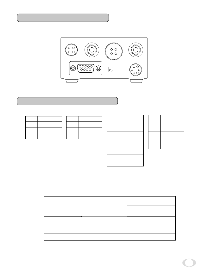
4.3 Connection on Back Panel
The figure below shows the back panel connection terminals of the camera control unit.
DC IN 12V EXT SYNC S-VIDEO
1
3
2
4
REMOTE
3
4
5
1
2
6789
4
2
FUNC LOCK
ON
OFF
3
1
VIDEO
IRIS
6
5
4
1
2
3
4.4 Connector Pin Assignments
DC IN 12V
1
+12V
2
+12V
3
GND
4
GND
S-VIDEO
1
2
3
4
GND
GND
Y
C
* When using the REMOTE terminal, please consult with your dealer.
REMOTE
1
2
3
4
5
6
7
8
9
NC
TXD
RXD
DSR
GND
DTR
CTS
RTS
NC
IRIS
1
NC
2
VIDEO
3
GND
4
+12V
5
GND
6
NC
• Using the auto-iris lens
The following table shows the IRIS terminal when using the auto-iris (EE) lens.
Table 1
IRIS Connector
Terminal No.
1
2
3
4
5
6
Signal
––
Video signal
GND
Power (DC)
(GND)
––
Rated
0.8 ± 0.1Vp-p
+ 12V (less than 50mA)
The IRIS connector used for the IRIS terminal: HR10A-7P-6P of HIROSE ELECTRIC
CO., LTD.
9
 Loading...